7
1. Adjusting N2 gas of front and rear suspensions
Adjust the quantity of N2 gas (front and rear, 4 places).
1. Loosen the air bleeding valves of the right and left front suspension cylinders and bleed air thoroughly. (Check that air does not come
out any more (and only oil flows out) and tighten the valves again. Tightening torque: 39.2 – 49.0 Nm {4 – 5 kgm})
2. Check that the valves are closed and install the suspension gas pouring tool to the gas cylinder.
3. Connect the hoses of the suspension gas pouring tool to the nitrogen gas pouring valves. (Since there are 2 hoses, connect them to
the right and left suspension cylinders and pour the nitrogen gas simultaneously so that pressure will be applied to both cylinders even-
ly.)
4. Open the valve of the suspension gas pouring tool gradually.
5. When the suspension cylinders rise to the specified level shown above, close the valve. (Pour the gas to the front suspension cylinders
until they rise to the level indicated by the decalcomania. Pour the gas to the rear suspension cylinders until they rise to the level shown
in the above figure.)
6. Remove the hoses from the nitrogen gas pouring valves and move the machine forward and in reverse to fit the suspension cylinders,
and then stop without applying the brake. (Finally, stop the machine without applying the brake to prevent an uneven load caused by
braking.)
7. Apply the parking brake and check the length of the suspension cylinders.
8. If the length of the suspension cylinders is out of the standard range, repeat steps 3 - 7. (Usually, adjustment is completed by repeating
those steps 3 - 4 times.)
Assembly procedure No.
Adjusting N2 gas of front and rear suspensions
No.0500
Dimension A (Front side) Dimension A (Rear side)
When cylinder is retracted fully: MIN (32 ± 1 mm) When cylinder is retracted fully: MIN (26 ± 1 mm)
Specified quantity of filled oil: OIL 53 ± 3 mm Specified quantity of filled oil: OIL 66 ± 3 mm
When empty: EMPTY (153 ± 10 mm) When empty: EMPTY (96 ± 5 mm)
When cylinder is extracted fully: MAX (209 ± 1 mm) When cylinder is extracted fully: MAX (116 ± 1 mm)
Precautions Necessary tools Necessary equipment
1. Bleed air from the cylinders.
2. Pour nitrogen gas in the right and left
suspension cylinders simultaneously.
3. Do not extend the suspension cylinders
to the stroke end.
4. After moving the machine forward and in
reverse, stop it without applying the
brake.
5. Do not steer the machine before
finishing this adjustment. (If it is steered,
the piping may be broken.)
Name Q’ty Name Q’ty
Suspension gas pouring tool 1
(7926-10-1000)
Others
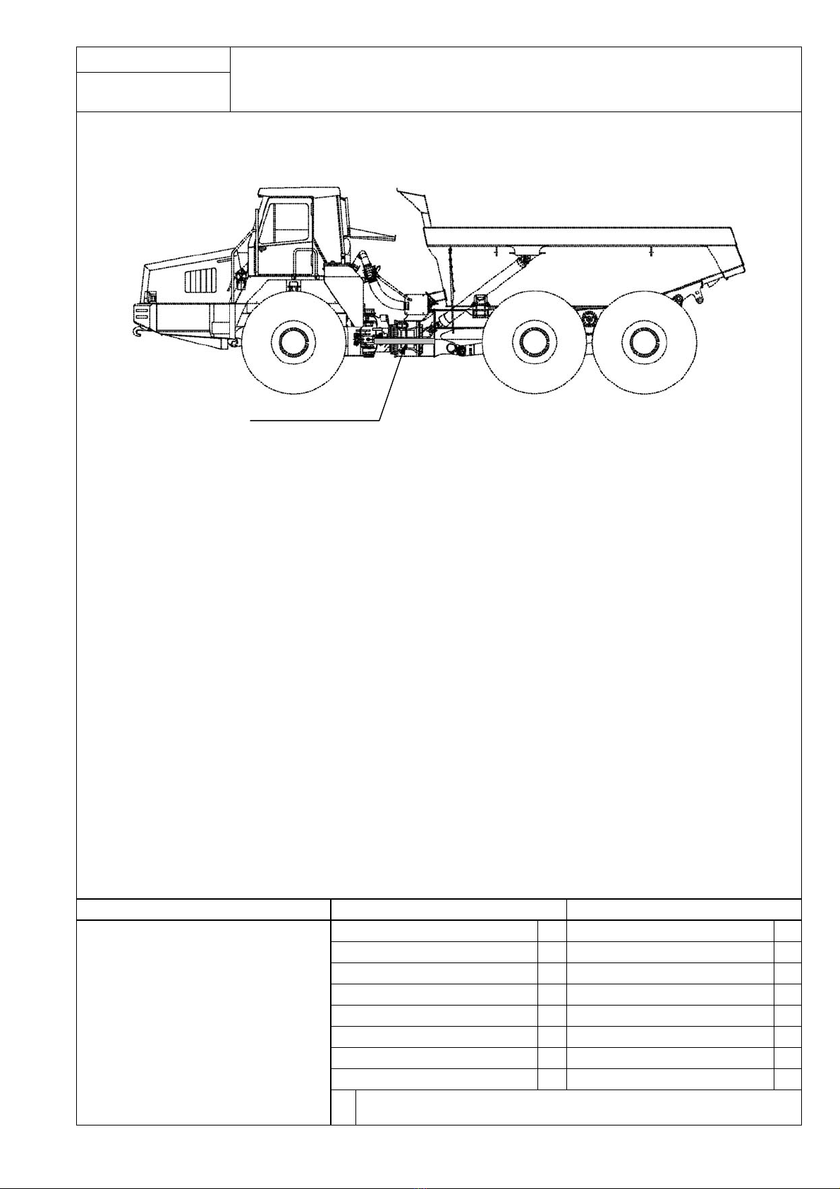
Front
suspension
Before adjusting suspension gas,
remove the cover. After adjusting install it.
Air bleeding valve
Air bleeding hole
N2 gas pouring valve Installing position of suspension gas pouring tool
N2 gas cylinder
Suspension gas pouring tool
(7826-10-1000)
i
Chassis side
Front suspension cylinder Rear suspension cylinder
Axle side
o
i
Chassis side
Axle side
o


 Operator's manual")