PreXion PreXion3D Excelsior User manual

XTR-PX2-C0006-IN004 Cover Page ii
i. general notes
Regarding the following items about PreXion3D Excelsior, refer to "Introduction" chapter of "PreXion3D
Excelsior Operation Manual (XTR-PX2-C0002-006)".
- Manufacturer's Liability
- Symbols and Notation
- Precautions
- Responsibility of Customer
- Product Lifetime
- EMC Standard Compliance
- Storage and Usage Environment
- Move and Transport
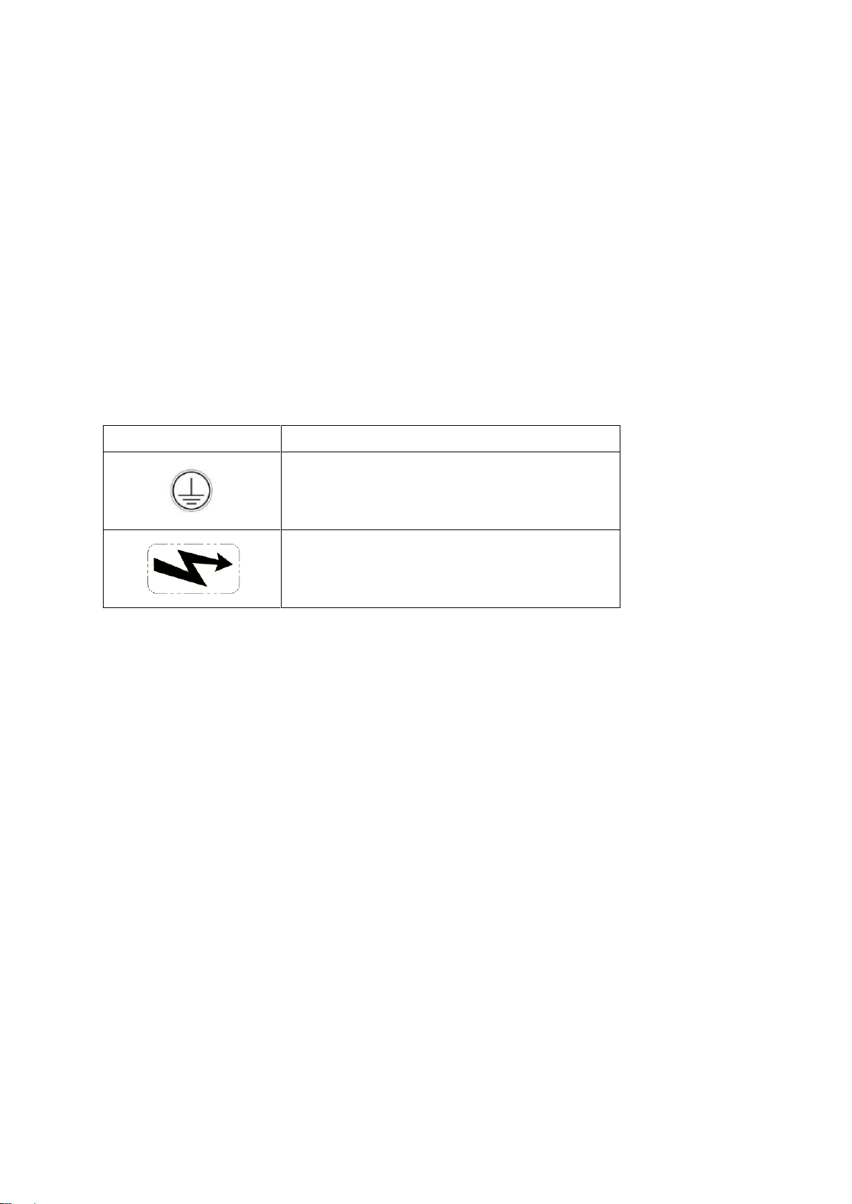
Other than Symbols described in "Introduction :i.3.2", there are the following two labels inside the equipment.
Symbol
Meaning
Protective Earth
Caution about High Voltage
ii. specification of the equipment
Regarding the specification of PreXion3D Excelsior, refer to chapter 7 of "PreXion3D Excelsior Operation
Manual (XTR-PX2-C0002-006)"
iii. requirement for installation place
Refer to the Installation Manual.
iv. Image QA
Regarding Image QA of PreXion3D Excelsior, the procedure is described in " PreXion3D Excelsior Operation
Manual ".
v. User operation of the equipment
Refer to the following two Operation Manuals.
- PreXion3D Excelsior Operation Manual (XTR-PX2-C0002-006)
- PreXion3D Excelsior Viewer Manual (XTR-PX2-C0008-002)

XTR-PX2-C0006-IN004 Stand 1
Installation Manual of Excelsior Stand Apr. 28th 2017
index
1.Packing contents...............................................................................................................................................2
1-1. appearance................................................................................................................................................2
1-2. contents.....................................................................................................................................................2
1-3. not included in the packing........................................................................................................................ 2
1-4. main parts..................................................................................................................................................3
2. space for the installation ..................................................................................................................................4
2-1. required floor space...................................................................................................................................4
2-2. wall anchor vertical position ......................................................................................................................4
2-3. wall anchor horizontal position..................................................................................................................4
3. building up........................................................................................................................................................ 5
3-1. attach the Grip on the STAND BASE........................................................................................................5
3-2. Attach Adjusters on the STAND BASE......................................................................................................5
3-3. Confirm and adjust the horizontal levelness .............................................................................................5
3-4. covering the STAND BASE .......................................................................................................................5
3-5. Attach NUT with NUT HOLDER on the BASIC FRAME (16 locations )..................................................6
3-6. Build BASIC FRAME on the STAND BASE ..............................................................................................6
3-7.Attach STAND PLATE TOP on the top of BASIC FRAME with 4 screws tightly .......................................7
3-8.Attach STAND BRACKET parts on the BASIC FRAME tentatively...........................................................7
3-9. Confirm the wall fixing point and screw the BOARD ANCHOR into the wall plate...................................7
3-10. Affix the wall BRACKET by board anchor screws with washers ( 10 locations ).................................... 7
3-11. Place Excelsior PILLAR ASSY on the STAND BASE .............................................................................7
3-12. Attach WALL PLATE on the BASIC FRAME...........................................................................................7
3-13. Affix PILLAR ASSY at the STAND BASIC FRAME tentatively ...............................................................8
3-14. Fix the screws tightly by the following order ...........................................................................................8
4. attached screws list.......................................................................................................................................... 8
5. Torque............................................................................................................................................................... 8
XTR-PX2-C0006-IN004 Stand 2
1.Packing contents
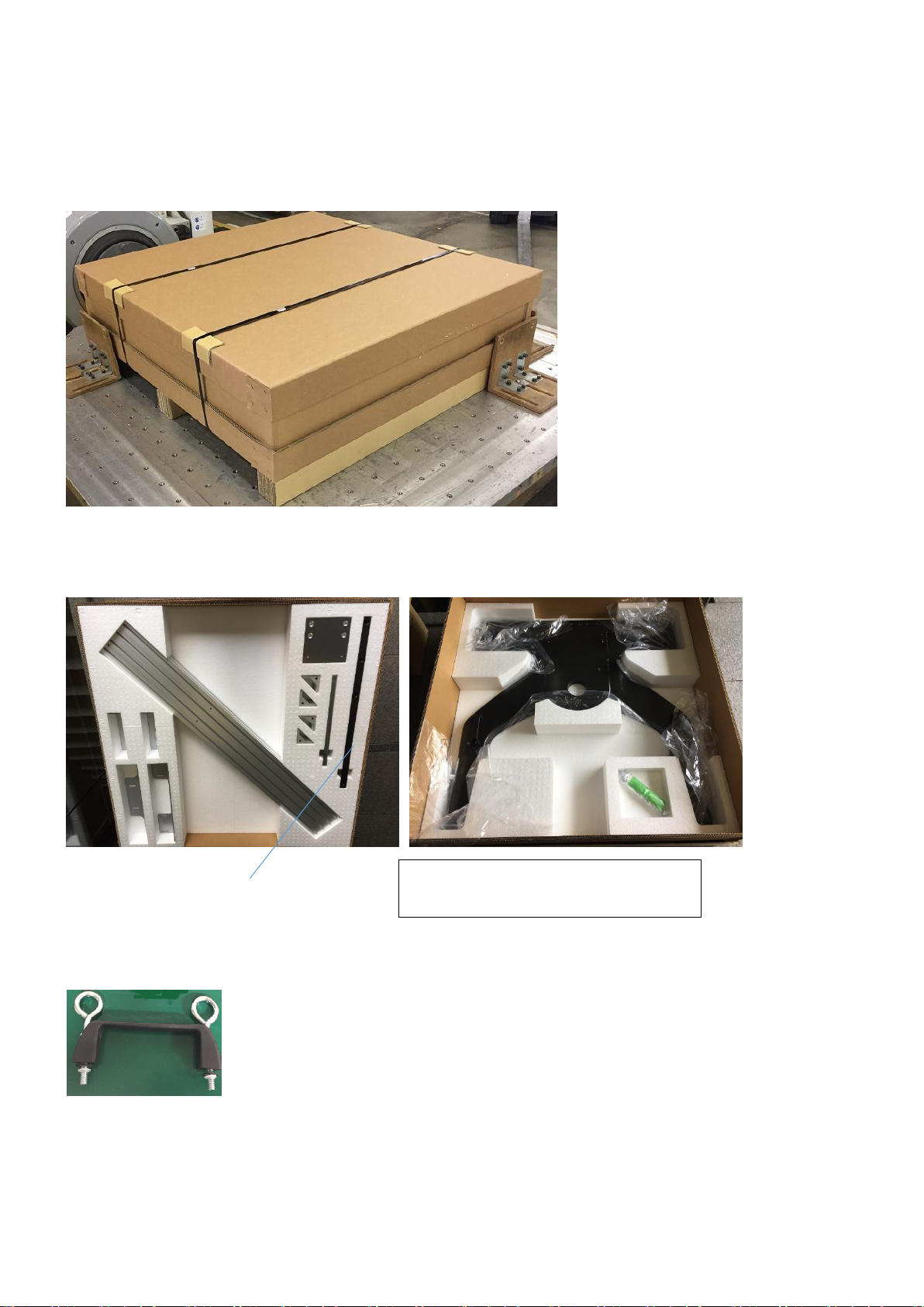
1-1. appearance
Size: :1280 x 1280 x 395 mm (50 inch x 50inch x 15 inch)
Weight(whole) :110kg (242 lbs)
Weight(base plate only ):50kg (110 lbs)
1-2. contents
This is two layers packing.
lower layer upper layer
* Bar for the Ceph option is not included.
1-3. not included in the packing
The Grip for the base plate is not included in the package. ( These are provided as service tools )
The first 25 packages has Stand Base
in the lower layer.

XTR-PX2-C0006-IN004 Stand 3
1-4. main parts
STAND BRACKET TOP
WALL PLATE
STAND BRACKET BOTTOM
STAND BRACKET MIDDLE (2)
STAND PLATE TOP
BASIC FRAME
GRIP (4) = Service tool
STAND BASE
HEAVY BRACKET (4)
ADJUSTER (6)

XTR-PX2-C0006-IN004 Stand 4
2. space for the installation
2-1. required floor space
2-2. wall anchor vertical position
board anchor position
2-3. wall anchor horizontal position
left-right symmetry position
100 ±10 mm
1000 ±10 mm
According to the position of
STAND BRACKET, height
can be changed greatly.
1500 ±10 mm
250 mm
100 mm
100 mm
320 mm
TOP & Bottom
middle
/ / / / / / / / / / / / / / / / / / / / / / / / / / / / / / / /
XTR-PX2-C0006-IN004 Stand 5
3. building up
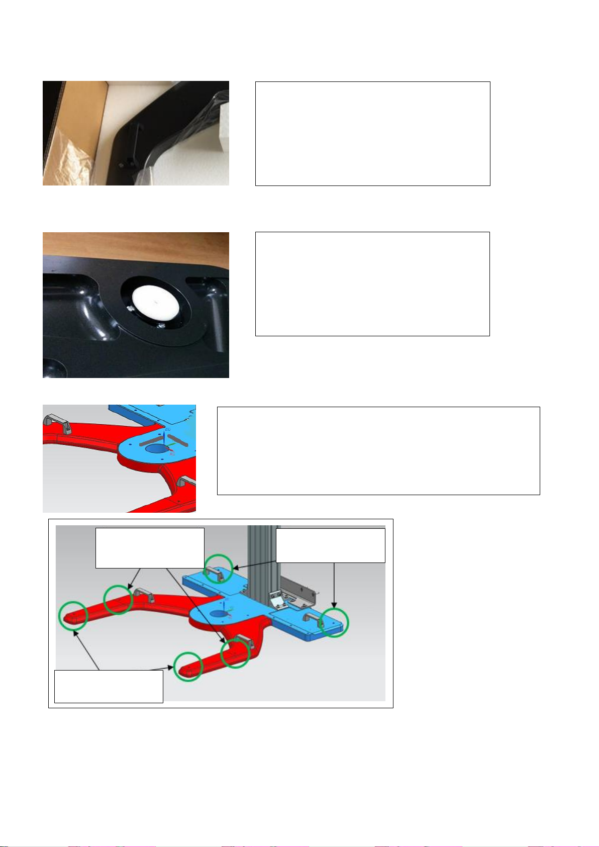
3-1. attach the Grip on the STAND BASE
3-2. Attach Adjusters on the STAND BASE
3-3. Confirm and adjust the horizontal levelness
3-4. covering the STAND BASE
The surface paint coating on the STAND BASE is very fragile. Not to damage the surface during the
installation work, cover the STAND BASE plate with protection material ( by pieces of cardboard box, or
cushion material or blanket )
Remove the upper layer package.
attach the Grip on the STAND BASE
( 4 locations )
Take out the STAND BASE,
Attach the ADJUSTER by hand
(6 locations)
Note: This process is done in the factory.
Among 6 adjusters,
adjust left and right levelness by two wall side Adjusters,
and adjust front and back levelness by two middle Adjusters.
Two front Adjusters just support the machine and we don't use
them as levelness adjuster.
BASE FRAME is not installed
yet in this situation.
wall side two Adjusters
for left and right levelness
middle two Adjusters
for front back levelness
front two Adjusters
just to support the body

XTR-PX2-C0006-IN004 Stand 6
3-5. Attach NUT with NUT HOLDER on the BASIC FRAME (16 locations )
3-6. Build BASIC FRAME on the STAND BASE
Attach HEAVY BRACKET at bottom with HEAVY BRACKET tentatively( 16 screws ).
Remember the BASIC FRAME has top/bottom direction.
Attach the HOLDER at the NUT and insert them
in the ditch in the surface. And slide them to the
proper location.
Place NUT in the upper side ( surface side ) on
the HOLDER.
Caution:
BASIC FRAME has top and bottom direction.
On the top surface, screw holes are tapped for the STAND
PLATE TOP.
screw holes on the top
16 locations for NUT and NUT HOLDER
for STAND BRACKET MIDDLE
( 2 x 2 = 4 )
for STAND BRACKET BOTTOM
( 2 x 4 = 8 )
for WALL PLATE
( 4 )
BASIC FRAME
STAND BASE
HEAVY BRACKET (4)
960 mm
882 mm
60 mm
BASIC FRAME edge
Screw Bag G
Screw Bag D
Screw Bag B
Screw Bag D
Screw Bag B
Screw Bag C

XTR-PX2-C0006-IN004 Stand 7
3-7.Attach STAND PLATE TOP on the top of BASIC FRAME with 4 screws tightly
3-8.Attach STAND BRACKET parts on the BASIC FRAME tentatively
- Attach STAND BRACKET TOP onto the BASIC FRAME by two screws
- Attach STAND BRACKET MIDDLE onto the BASIC FRAME by two screws x 2
- Attach STAND BRACKET BOTTOM onto the BASIC FRAME by four screws
3-9. Confirm the wall fixing point and screw the BOARD ANCHOR into the wall plate
( in total 10 locations for top, middle, and bottom )
3-10. Affix the wall BRACKET by board anchor screws with washers ( 10 locations )
3-11. Place Excelsior PILLAR ASSY on the STAND BASE
Screw the bottom tentatively
3-12. Attach WALL PLATE on the BASIC FRAME
board anchor
board anchor ( same as above )
not tightly yet
tightly for 4 locations
( height 882mm )
with washers
When possible,
confirm the horizontal levelness
before placing the Pillar Assy.
Screw Bag D
Screw Bag B

XTR-PX2-C0006-IN004 Stand 8
3-13. Affix PILLAR ASSY at the STAND BASIC FRAME tentatively
3-14. Fix the screws tightly by the following order (1), (2), (3), (4) and (5)
4. attached screws list
bag number
screw type
qty
remarks
A
CP10X40-CM1
4
Excelsior Wall Bracket
WASHER SW10
4
Excelsior Wall Bracket
B
CP8X25-I3-CM1
8
WALL PLATE x4
STAND BRACKET MIDDLE x4
C
CP8X25-I3-CM1
16
HEAVY BRACKET x16
D
CP8X30-I3-CM1
10
STAND BRACKET BOTTOM x4
STAND BRACKET TOP x2
STAND PLATE TOP x4
E
WASHER W4
10
for wall
F
WALL ANCHOR SCREW
10
for wall
G
NUT and others
16
STAND BRACKET MIDDLE x4
WALL PLATE x4
HEAVY BRACKET x8
* Screw bag C and D have the same screws.
5. Torque
Screw size
torque
remarks
M8 screws
17.2 Nm
M10 screws
25.0 Nm
6 screws tentatively
(1) Excelsior bottom
(4 screws)
(2) Excelsior bottom
(6 screws)
(3) Stand bottom
(24 screws)
(4) Stand middle
(6 screws)
(5) Stand top
(6 screws)
4 screws are from Screw Bag A
Other 2 screws are
from Excelsior scanner Screw Bag R
from Screw Bag A

XTR-PX2-C0006-IN004 i
PreXion3D Excelsior Installation Manual Contents : Scanner Unit 3 July 2017
1. Requirement for installation................................................................................................................... 1-1
1.1 Space for unpacking the device ................................................................................................................ 1-1
1.2 Information of the packing boxes............................................................................................................... 1-2
1.3 Size of the installation space..................................................................................................................... 1-3
1.4 Requirement for the X-ray Scanner room ................................................................................................. 1-5
1.5 Power requirements (for Scanner) ............................................................................................................ 1-6
1.6 Power Requirements (Console) ................................................................................................................ 1-7
1.7 Floor load capacity .................................................................................................................................... 1-7
1.8 Fixing the device to the floor...................................................................................................................... 1-8
1.9 Fixing the device to a wall ....................................................................................................................... 1-10
2. Contents of Each Carton ........................................................................................................................ 2-1
3. Building the device.................................................................................................................................. 3-1
3.1 Setting up the PILLAR............................................................................................................................... 3-2
3.2Attaching the Stationary Arm..................................................................................................................... 3-4
3.3 Attach the SENSOR BASE........................................................................................................................ 3-5
3.4 Wiring to the SWITCH Box........................................................................................................................ 3-8
3.5 Attaching the SWITCH Box..................................................................................................................... 3-11
3.6 Attaching the cover (FIXED COVER BOTTOM only).............................................................................. 3-12
3.7 Attaching the Rotation Arm...................................................................................................................... 3-13
3.8 Attaching the Chin Rest Arm................................................................................................................... 3-19
3.9 Attaching the LCD ................................................................................................................................... 3-20
3.10 Attaching Cephalometric Sensor Unit (optional) ..................................................................................... 3-20
4. Wiring........................................................................................................................................................ 4-1
5. Confirming stand-alone operation (Control panel operation) ............................................................ 5-1
6. Connecting the Console ......................................................................................................................... 6-1
6.1 Connecting the Scanner and the Console................................................................................................. 6-1
6.2 Connecting the Scanner and the Console................................................................................................. 6-1
7. Adjustment............................................................................................................................................... 7-1
7.1 Performing daily check .............................................................................................................................. 7-1
7.2 Adjusting Collimator’s home position angle (Colli Calib and Panorama Alignment)................................. 7-3
7.3 Adjusting Collimator’s position (CT Small Alignment) ............................................................................... 7-6
7.4 Attaching the Geometry phantom (Small sphere phantom)...................................................................... 7-9
7.5 Adjusting geometry (FPD Center) ........................................................................................................... 7-10
7.6 Adjusting FPD Tilt.................................................................................................................................... 7-12
7.7 Adjusting geometry (Center of the Rotation XY)..................................................................................... 7-14
7.8 Detaching the Geometry phantom (Small sphere phantom)................................................................... 7-15
7.9 Adjusting the panorama offset................................................................................................................. 7-16
7.10 When adjustment work does not finish.................................................................................................... 7-18
8. Attaching the cover, hand grip and laser position adjustment knob................................................. 8-1
8.1 Attaching the cover.................................................................................................................................... 8-1
8.2 Attaching the Handgrip............................................................................................................................ 8-12
8.3 Attaching the Chin rest assembly............................................................................................................ 8-13
9. Confirming the image quality................................................................................................................. 9-1
10. Materials................................................................................................................................................. 10-1
10.1 Accessories ............................................................................................................................................. 10-1
10.2 Cable ties proved with the product.......................................................................................................... 10-3
10.3 Jig and tool list......................................................................................................................................... 10-4
10.4 Tightening torque list ............................................................................................................................... 10-4
XTR-PX2-C0006-IN004 1-1
1. Requirement for installation
1.1 Space for unpacking the device
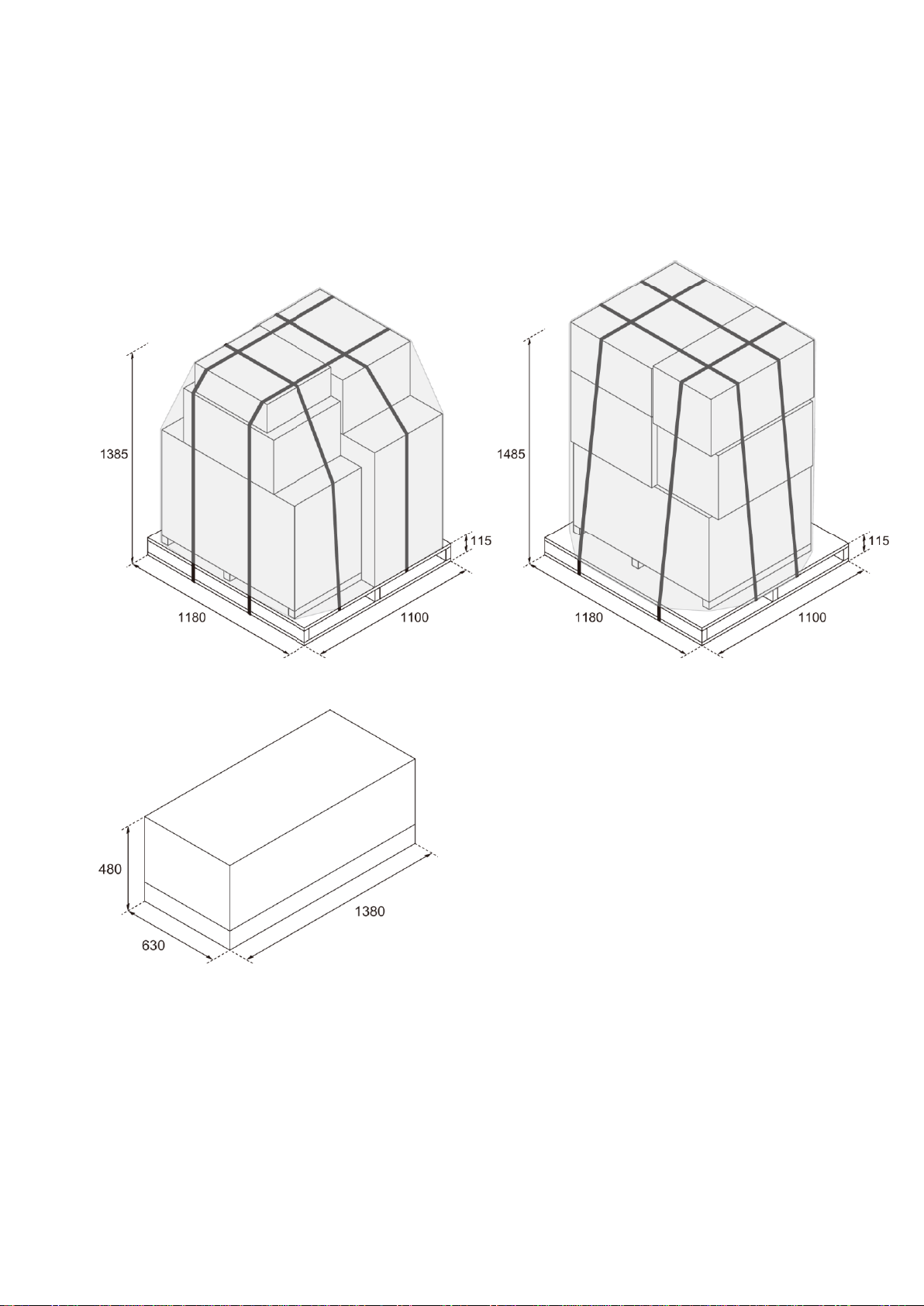
PreXion3D Excelsior is delivered from the factory in the following packing specification.
You will need a space to unpack it.
If your device comes with a Cephalometric Sensor Unit, the following package will also come with the device.

XTR-PX2-C0006-IN004 1-2
1.2 Information of the packing boxes
Each package is provided with a label indicating the contents.
<Label Image>
Pallet No.
Box No.
Name
1
1
ARM PILLAR ASSY BOX
1-1
FIXED ARM COVER BOX
2
ROTARY ARM ASSY BOX
5
ACCESSORY BOX
2
3
CHINREST ASSY BOX
4
DC PILLAR BOX
6
ROTARY ARM COVER 1 BOX
7
PILLAR COVER BOX
8
ROTARY ARM COVER 2 BOX
Confirm each box has the same serial number label on it.
Box No.
Name
Pallet No.
XTR-PX2-C0006-IN004 1-3
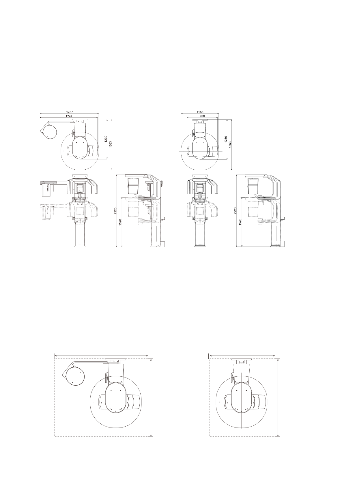
1.3 Size of the installation space
(1) For Scanner
The device size is below:
<With Cephalometric Sensor Unit>
<Without Cephalometric Sensor Unit>
Height 1,520 to 2,220 mm
Width 1,747 (max. 1,787) mm
Depth 1,230 (max. 1,563) mm
Height 1,520 to 2,220 mm
Width 930 (max 1,158) mm
Depth 1,230 (max. 1,563) mm
You can set the height of the device (when it is extended to the very top of the gantry) in the following five
stages:
2,220 mm, 2,170 mm, 2,120 mm, 2,070 mm, 2,020 mm
For all heights, the lowest point (when the gantry is lowered to the lowest point) is the same.
The following area is required for the installation space (including the maintenance space)
<With Cephalometric Sensor Unit>
<Without Cephalometric Sensor Unit>
Width 2,090 mm or more
Depth 1,750mm or more
Width 1,460 mm or more
Depth 1,750 mm re more
2,090 mm or more
1,750 mm or more
1,750 mm or more
1,460 mm or more

XTR-PX2-C0006-IN004 1-4
(2) For Console PC
The Console PC size is below;
The size and weight that described here are an example.
- PC (tower type) : Approximately 172 (W) x 471 (D) x 414 (H) mm (weight: approximately 13,500 g)
- Keyboard : Approximately 460 (W) x 190 (D) x 30 (H) mm (weight: approximately 900 g)
- Mouse : Approximately 64 (W) x 112 (D) x 36 (H) mm (weight: approximately 90 g)
- Display : Approximately 446 (W) x 147 (D) x 380 (H) mm (weight: approximately 5,800 g)
Normally, the Exposure Switch and emergency stop switch are also placed in this area.
- Exposure Switch: 39 (W) x 38 (D) x 144 (H) mm (weight: approximately 65 g)
- Emergency stop switch: 76 (W) x 76 (D) x 80 (H) (when the emergency stop switch is released) mm
(weight: approximately 160 g)
XTR-PX2-C0006-IN004 1-5
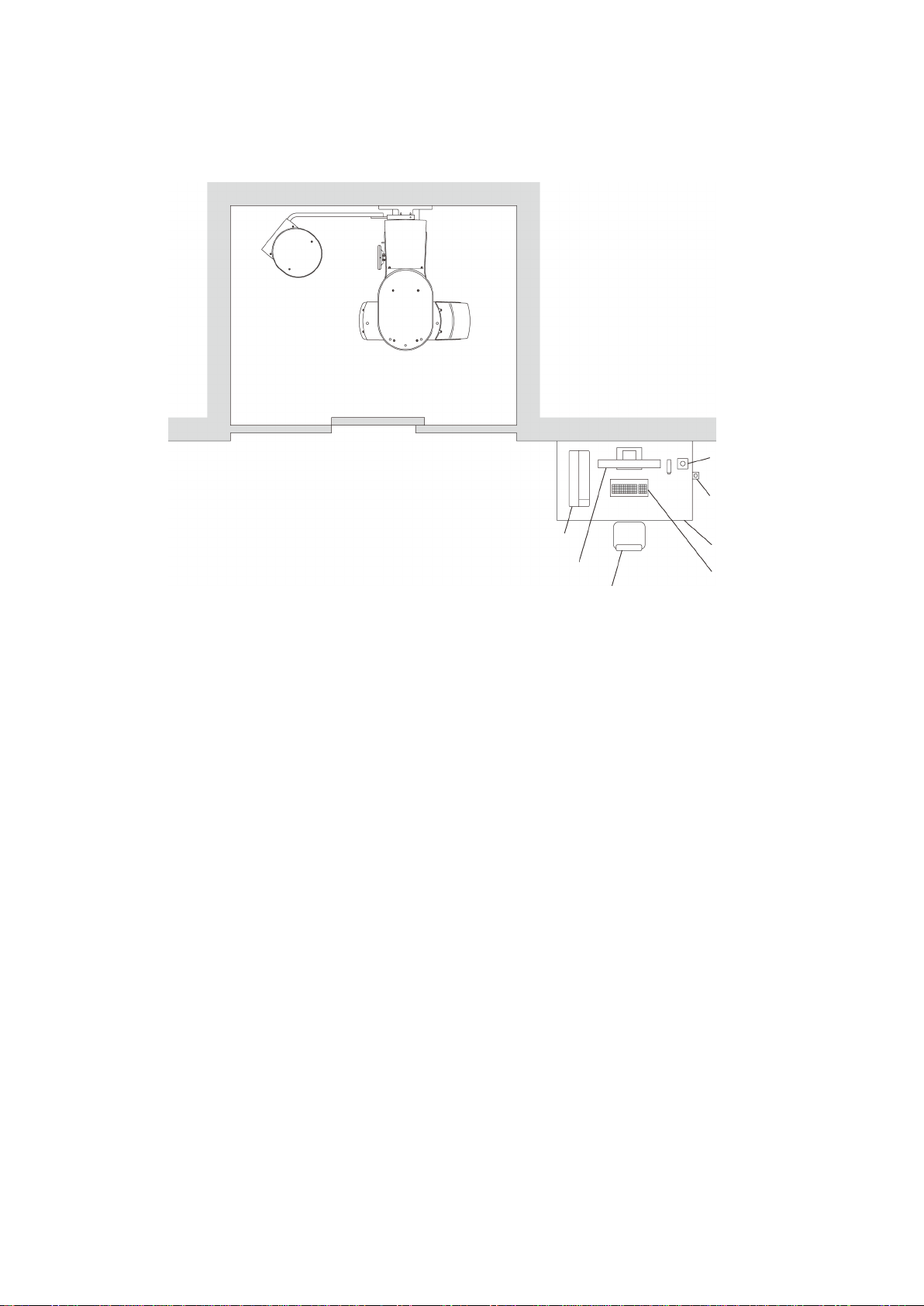
1.4 Requirement for the X-ray Scanner room
Prepare an X-ray Scanner room that has the space for installing the Scanner listed in “1.2 Size of the
installation space”. Also place the Console outside the X-ray room.
< Arrangement example >
Emergency stop switch
Exposure switch
Table
Keyboard
Chair
Monitor
PC
X-ray
Scanner room
XTR-PX2-C0006-IN004 1-6
1.5 Power requirements (for Scanner)
(1) Consumption current of the device
Make sure that the device that supplies power to the PreXion3D Excelsior has an apparent resistance value of
0.1 Ω or less.
(2) Power cable
Use a power cable to connect the distribution board to the PreXion3D Excelsior that meets the following
conditions:
・Thickness: AWG14 or more
・A cable that conforms with the local electricity safety standards (for America, that is the NEC)
* Be sure to ground the device.
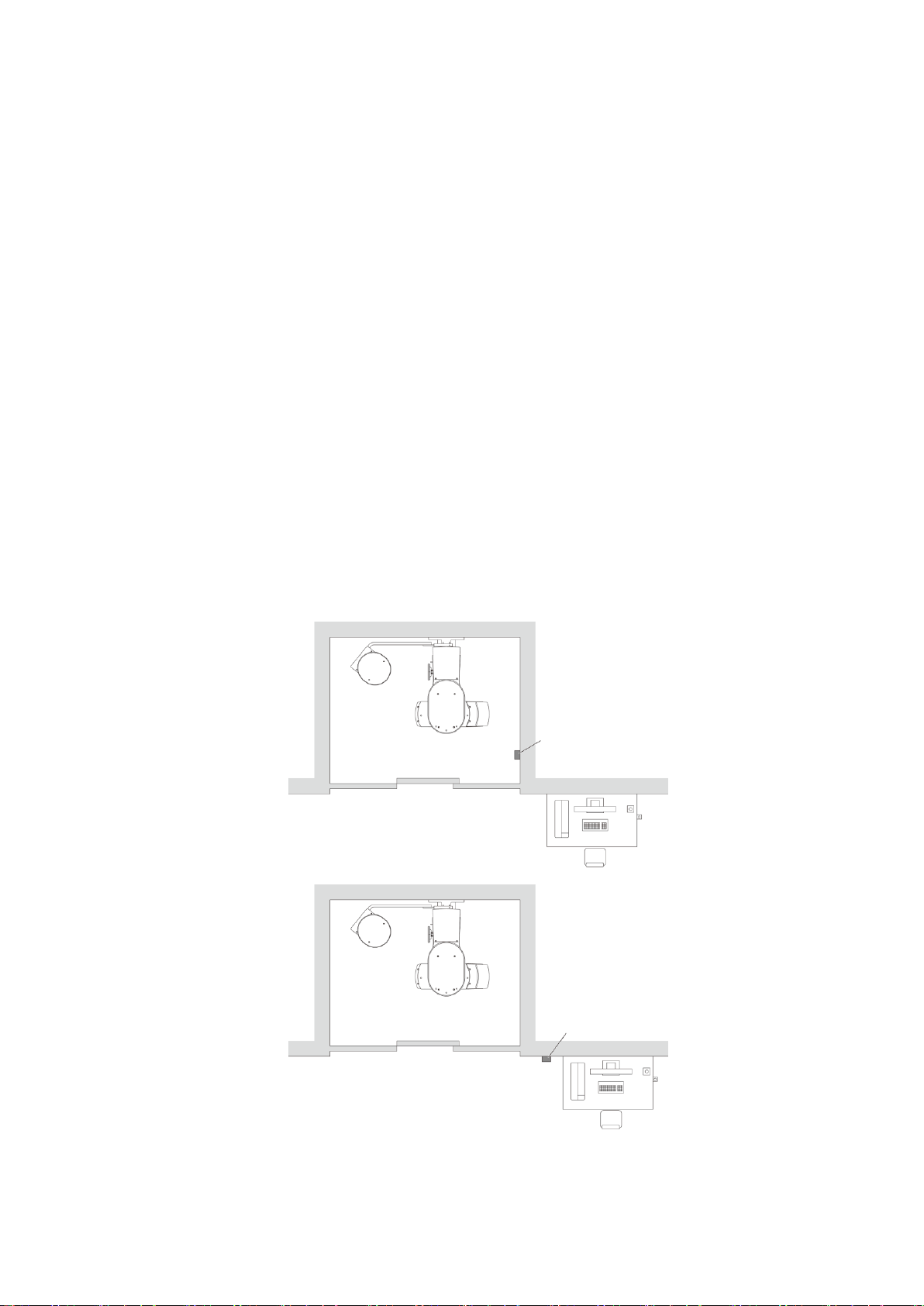
(3) Installing the additional breaker
The PreXion3D Excelsior is a permanently installed device and is supplied power by the distribution board in
the building.
To ensure safety, connect the electric cable that connects the distribution board to the device to a dedicated
circuit breaker in between. Prepare a dedicated circuit breaker that is 15 A.
Before a service engineer performs maintenance, make sure to turn off this circuit breaker.
< Arrangement example >
The PreXion3D Excelsior unit is equipped with the following current interruption characteristics:
・Standard current rating: 15 A or more
・Rated interruption capacity: 1000 A / AC 240 V or more
Breaker
Breaker

XTR-PX2-C0006-IN004 1-7
1.6 Power Requirements (Console)
Connect the Console to a standard commercial power supply.
- PC : AC100-240V, 50/60Hz, 700W or lower
- Display : AC100-240V, 50/60Hz, 100W or lower
1.7 Floor load capacity
The floor must be able to withstand the weights of the device (without the Cephalometric Sensor Unit: 165 kg;
with the Cephalometric Sensor Unit: 200 kg), the patient, the operator, and so on.
Recommended load capacity =500 kg/m2
XTR-PX2-C0006-IN004 1-8
1.8 Fixing the device to the floor
The PreXion3D Excelsior is a device which is assumed that will be anchored to the floor with anchor bolts to
actualize a small footprint. For customers who wish to avoid floor anchoring (anchor bolts), we have prepared
specialized pedestals.
●Strength required for the concrete
Compressive strength: 17.6 N/mm2 (light-weight concrete) or above
●Anchors and fixing bolts to be used (bundled with the device)
Anchor
(SANKO TECHNO Co., Ltd. : AG-1060)
No.
Diameter of
screw
Major diameter
(D)
Length
(L)
Diameter of
drill
Depth of
drill
1060
M10
14.5 mm
60 mm
15.0 mm
67.5 mm
Fixing bolt
Hexagon socket head M10
By fixing the anchors, the pull-out force of the anchor bolts achieved is 7,000 N or higher.
With a horizontal earthquake load of 1,900 N and a vertical earthquake load of 950 N, a sufficient load bearing
capacity can be ensured.
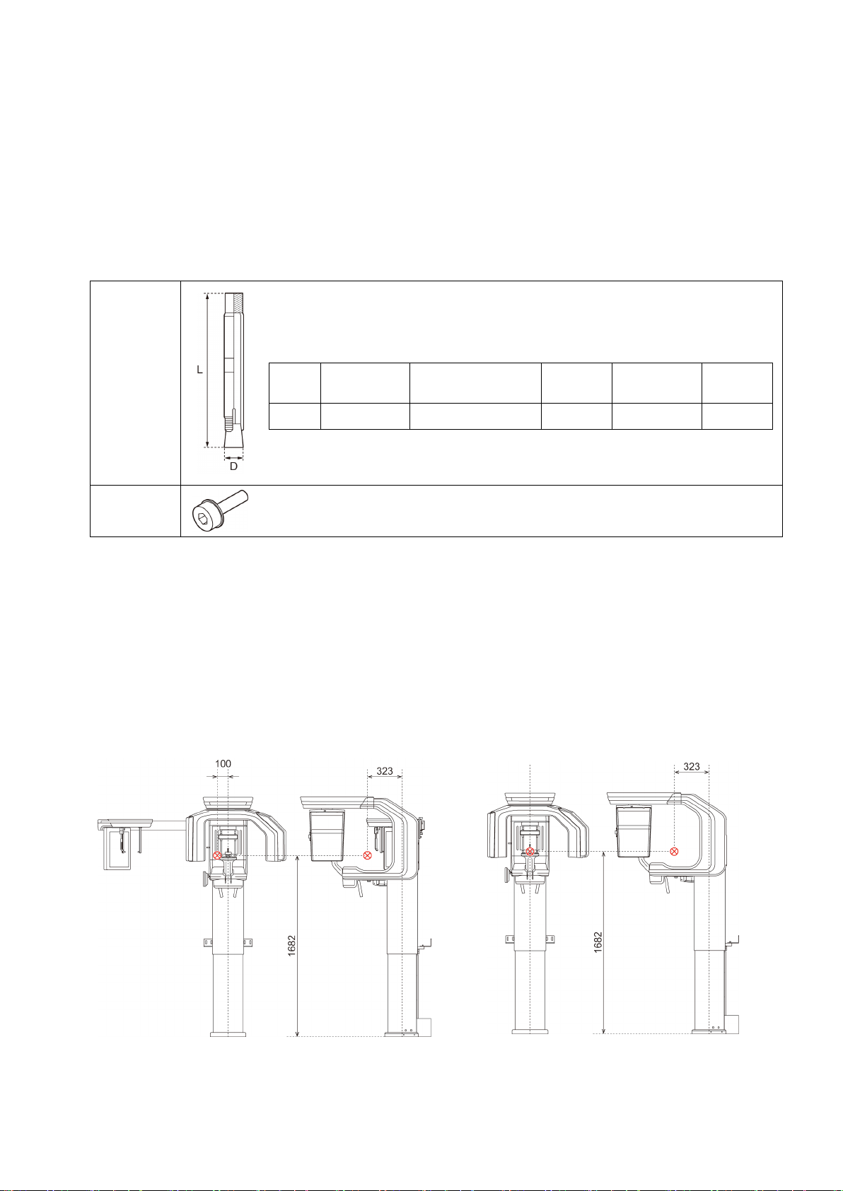
●Center of gravity
The center of the gravity with the gantry unit lifted to the top is as shown below.
<With Cephalometric Sensor Unit>
<Without Cephalometric Sensor Unit>
- 323 mm ahead from the center of the PILLAR
- 100 mm to the left from the center of the PILLAR
- 1682 mm from the floor
- 323 mm ahead from the center of the PILLAR
- The center of the PILLAR
- 1682 mm from the floor

XTR-PX2-C0006-IN004 1-9
● Anchor Position
* You can adjust the distance from the wall with bracket attachments secured to the wall by 141.5 mm to 171.5 mm.
●Installing the Anchor
The anchor attachment work needs to be performed before taking possession of the device.
・Making holes in the concrete floor (recommended tool: Kanzawa drill guide K-801)
・Cleaning the drilled holes
・Inserting the anchors
Making a hole in the concrete floor
Cleaning the drilled hole
Inserting the anchor
Table of contents
Popular Medical Equipment manuals by other brands


Life Changer
Life Changer Ganzfeld Light Mask user guide

VQ OrthoCare
VQ OrthoCare BIONICARE OACTIVE Application Instructions

Weinmann
Weinmann SOMNOsmart 2 Description and instructions for use

Otto Bock
Otto Bock Manu Immobil Long Instructions for use

Vendlet
Vendlet V5S Speed Adjust manual

Atlantic Therapeutics
Atlantic Therapeutics INNOVO Instructions for use

Invacare
Invacare Carroll CS3 user manual

Platoscience
Platoscience PlatoWork manual

Sanuvox
Sanuvox ASEPT.1X instruction manual

ECOPOSTURAL
ECOPOSTURAL C5551 instructions

Verity Medical
Verity Medical NeuroTrac MultiTENS Operator's manual

Preventice Solutions
Preventice Solutions BodyGuardian Heart instruction manual