Recessed Channel Installation Guide
3v001 | Recessed Channel Installation Guide
Site Conditions, Storage and Handling
• Read the Installation Guide before handling.
• Always wear appropriate hand protection when handling.
• Only store in clean, dry conditions.
• Do not over stack.
• Do not stack in a way likely to cause falls.
It is the responsibility of the installer to ensure that the materials delivered to the installation site are safeguarded
from the time of purchase until the nished ceiling is handed over. However, it is usually the main contractor who is
responsible for the conditions on site so both parties must be aware of the requirements of suspended ceilings for at
dry, clean and safe storage conditions.
Poor or rough handling, rolling or dropping of the product on corners or edges may cause damage to the product or the
product to deteriorate.
Lengths of Node should not span between points as any load applied mid-span may cause product damage.
Site storage of items should be at, preferably on a suitable pallet (supporting the entire length) without additional top
loading.
Consideration should be given to the advice of the Occupational Health and Safety Representative regarding manual
handling. An assessment should be made of any risk and if necessary mechanical lifting equipment should be used.
The storage space must be cleared of debris and, in general, should be enclosed. The Node Recessed Channel should be
kept clean, dry and protected from the elements.
Site conditions should be prepared for installation of the Node Recessed Channel. The site should be clean, dry and clear
of other trades working in the ceiling void.
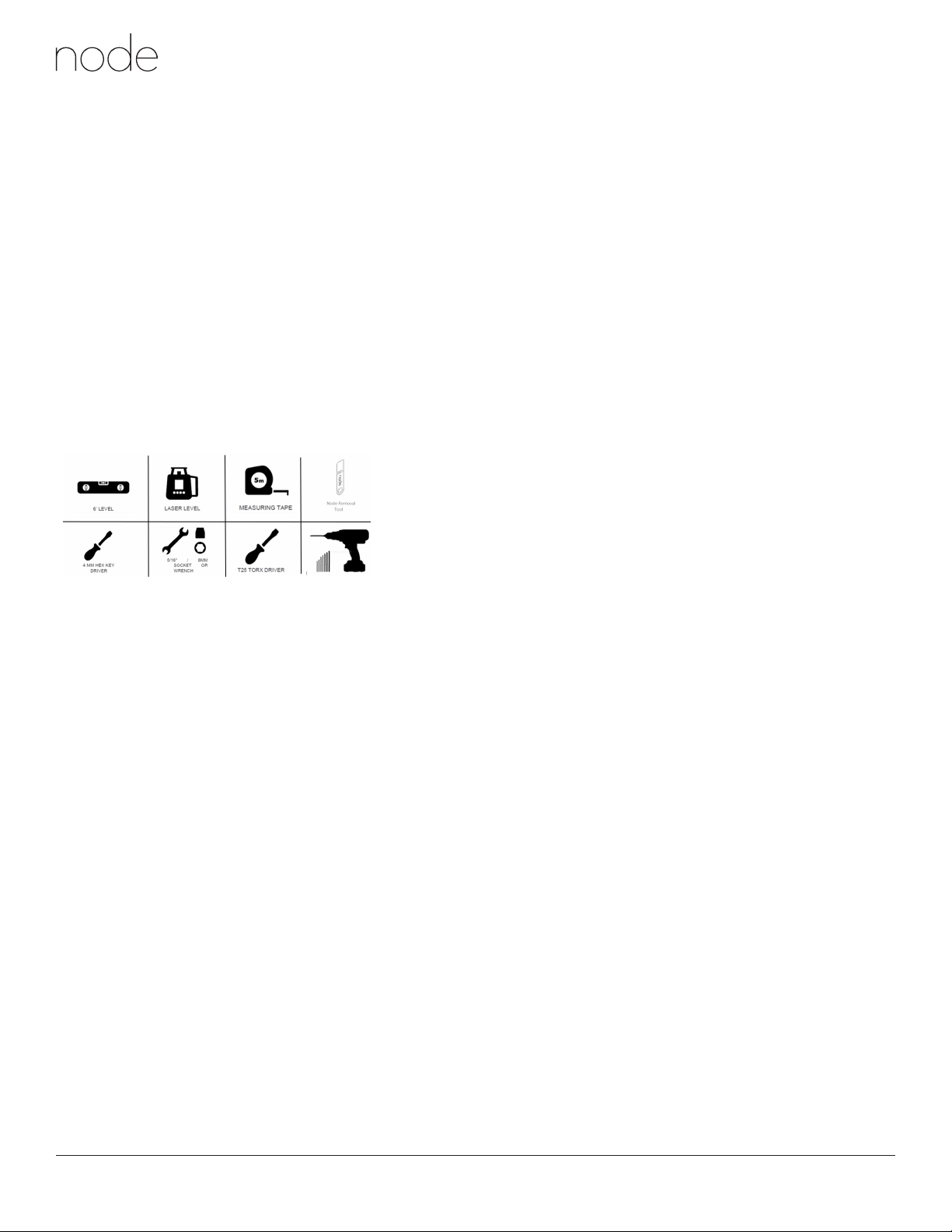
Tools Required
Recessed Channel
Installation Guide
3
Node Recessed Channel
Installation Guide
Site Conditions, Storage & Handling:
•Read the Installation guide before handling.
•Always wear appropriate hand protection when handling.
•Only store in clean dry conditions
•Do not over stack.
•Do not stack in a way likely to cause falls.
It is the responsibility of the installer to ensure that the materials delivered to the installation site are safeguarded from
the time of purchase until the finished ceiling is handed over. However it is usually the main contractor who is
responsible for the conditions on site so both parties must be aware of the requirements of suspended ceilings for flat
dry, clean and safe storage conditions.
Poor or rough handling, rolling or dropping of the product on corners or edges may cause damage to the product or the
product to deteriorate.
Lengths of Node should not span between points as any load applied mid-span may cause product damage.
Site storage of items should be flat, preferably on a suitable pallet (supporting the entire length) without additional top
loading.
Consideration should be given to the advice of the Occupational Health & Safety Representative regarding manual
handling. An assessment should be made of any risk and if necessary mechanical lifting equipment should be used.
The storage space must be cleared of debris and, in general, should be enclosed. The Node Recessed Plenum Channel
should be kept clean, dry and protected from the elements.
Site conditions should be prepared for installation of the Node Recessed Plenum Channels, the site should be clean dry
and clear of other trades working in the ceiling void.
Installation Sequence
:
The Node Recessed Plenum Channel ships fully assembled (skirts, mounting bracket, bridge plates and Node Face Plate).
Note: All mounting hardware and sub structure to be supplied and installed alongside the Node Flush Channel assembly.
Lighting & other services must be installed by qualified personnel.
It is recommended that the Node Recessed Channel is supported no more than 150mm from an end or 150mm from any
joint.
Read and save these instructions before beginning to install the Node Recessed Channel.
Warning! To reduce the risk of re, electric shock, or injury to persons, observe the following:
• When cutting or drilling into wall or ceiling do not damage electrical wiring and other hidden utilities
• Use this unit only in the manner intended by the manufacturer. If you have any questions, contact the
manufacturer or PARC Technical Support.
Before You Start
Inspect all product parts for aws and shipping damage.
If anything is discovered to be damaged, contact the shipping company and manufacturer immediately.
Warning! Damaged or missing parts must be reported to PARC at info@parc-ceilings.cominfo@parc-ceilings.com immediately, PARC will
not be responsible for any damage or loss that occurs during unpacking or installation.