Prier C-633 Guide
4515 E. 139th Street Grandview, MO 64030 | (800) 362-9055 | PRIER.com
Installation, Operation & Maintenance Instructions for the
PRIER C-633/C-634 Commercial Wall Hydrant
Please leave this sheet for the property homeowner
Thank you for purchasing the PRIER C-633/C-634 Commercial Wall Hydrant, the nest quality commercial
hydrant available. Your C-633/C-634 will provide you years of dependable service with little or no maintenance.
Please note: Your C-633/C-634 hydrant has drain holes under the packing nut. After shutoff, the drain holes will
allow water to drain for a few moments to prevent freezing. This is normal and according to design.
1. No special installation tools are required. Determine the location for installation of the hydrant. This valve
is designed for installation in either horizontal or vertical position. If installing vertically, install with hose
connection in “up” position.
2. Using the template provided on the box, bore a 1-3/8” diameter hole through the wall in the desired position,
and a ¼” alignment hole that is ½” deep.
3. Insert the hydrant through the hole and secure it to the inside wall using the provided wall clamping ring.
Seal through wall penetration if required.
4. Flush all foreign particles from the water line before connecting the hydrant.
5. Connect the water supply piping to the hydrant as desired. With a closed-end hose on the valve creating
back pressure, test the installation for leakage.
6. If planning to solder the hydrant to the supply piping, open the hydrant to the full open position before
soldering. Excess heat to the valve will damage the sealing surfaces on the stem of the hydrant.
INSTALLATION
Installation procedures may vary slightly depending on the seat option purchased and the installation inlet
options. The C-633/C-634 wall hydrant is available with the following inlet options:
Inlet Style Inlet Specications
N1” MPT x 3/4” FPT
P1” Male SWT x 3/4” Female SWT
V3/4” ProPress Ready
C-634 AND C-633NCC (Straight)
*P and V inlets not available on C-633NSV model
1. No special installation tools are required. Determine the location for
installation of the hydrant. This valve is designed for installation in either
horizontal or vertical position. If installing vertically, install with hose
connection in “up” position.
2. Using the provided template, Bore two holes through the wall and remove
the excess material between those to create an opening for the swivel inlet of
the valve.
3. Align your rotating inlet to the supply piping and secure the valve to the
outside wall. Seal through wall penetration if required.
4. Flush all foreign particles from the water line before connecting the hydrant.
5. Secure the hydrant to the supply piping and test for leakage with a closed-
end hose as described above.
C-633NSV (Swivel)
4515 East 139th Street
Grandview, MO 64030
(800) 362-9055
Fax (800) 362-1463
INSTALLATION:
5. Flush all foreign particles from the water line before
connecting the Freezeless Hydrant. Foreign particles
may clog the vacuum breaker/backflow preventor caus-
ing it to fail.
6. Insert the Freezeless Hydrant through the previously
bored hole and secure the hydrant to the inside of the
wall with the provided wall clamping ring.
7. Secure the Freezeless Hydrant to the supply piping.
Test the installation for leakage.
1. Determine the location for installation of the Freeze-
less Hydrant. Be sure there is adequate work area on
the interior of the structure for securing the Freezeless
Hydrant to the waterline.
3.Using the template provided on the box, bore a 1 3/8”
diameter hole through the wall in the desired position,
and a 1/4” hole that is 1/2” deep.
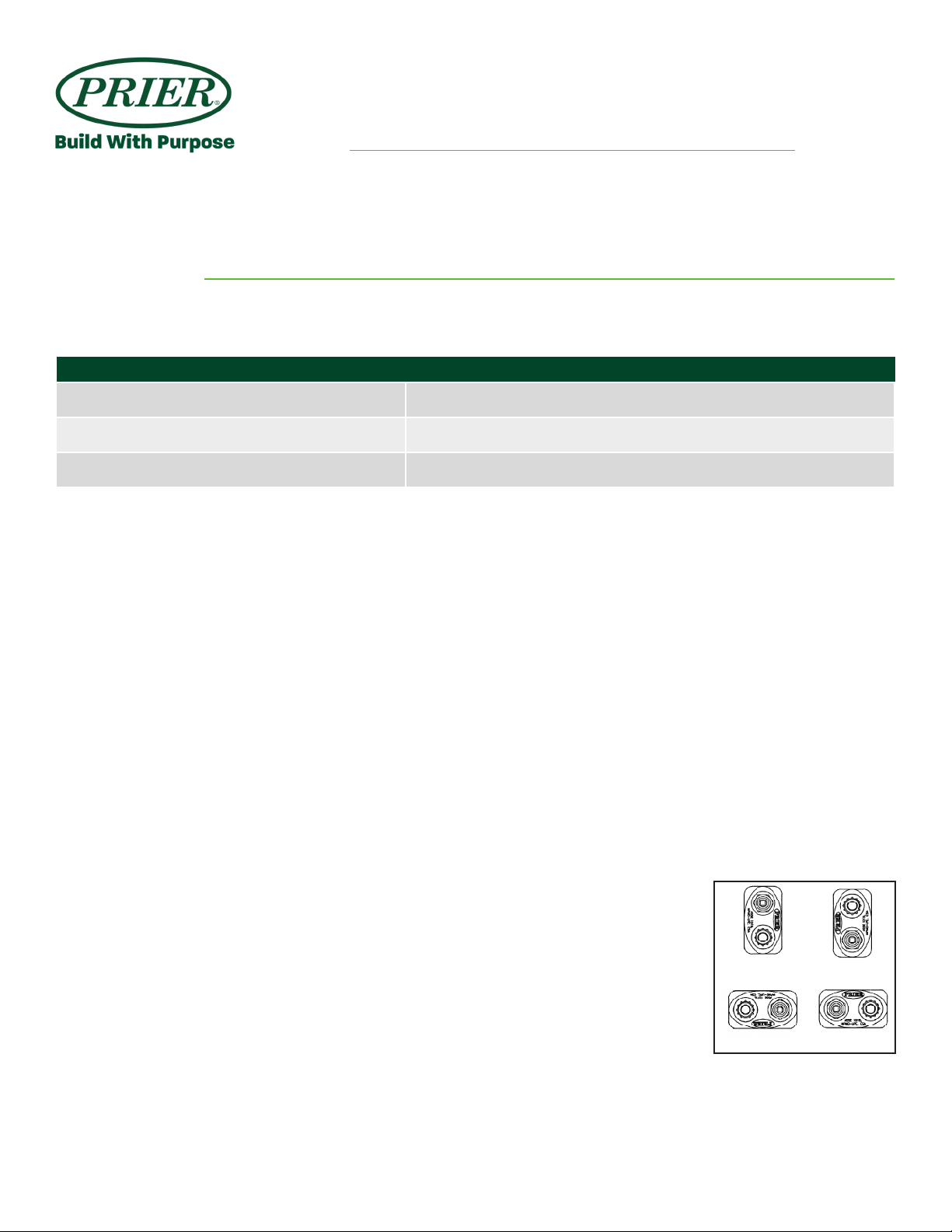
2. The Prier C-634 is designed for installation in either
horizontal or vertical position.If using vertical installa-
tion, it is recommended that the hydrant be installed with
the hose threads in the “up” position.Refer to drawings
to the right for correct installations.
4.If planning to solder the Freezeless Hydrant to the
supply piping, remove the operating stem before apply-
ing heat to the valve. Heating the valve will damage the
sealing surfaces on the stem of the Freezeless Hydrant
OPERATION:
The operation of a Prier C-634 Freezeless Wall
Hydrant is simple. The Freezeless Hydrant will
begin to flow at about 1 full turn of the key and will
achieve maximum flow at 2 1/2full turns.
After shutoff, the hydrant will drain water from be-
hind the packing nut. If the water drains for more
than 1 minute, the stopper may need to be replaced.
Do not overturn when opening or closing the hydrant!
MAINTENANCE:
The Prier C-634 Freezeless Wall Hydrant requires no
scheduled maintenance for long wear life. If the op-
erating stem is removed, replacement of the O-Ring
on the worm sleeve and worm drive is recommended.
Recommended
Acceptable
Not Recommended Acceptable
INSTALLATION,OPERATION & MAINTENANCE INSTRUCTIONS FOR
PRIER C-634 HEAVY COMMERCIAL WALL HYDRANTS
PARTS:
713
12
11
34
10
8
1
56
92
ID Part No. Description
1300-6003 Valve Stem Cap-Brass
2300-6004 Hose Piece-Brass
3336-0001 O-Ring for Worm Sleeve Buna
4336-6001 O-Ring for Worm Drive Buna
5337-6001 Stop Check-Acetal
6346-6001 VB Check Washer-Silicone
7399-6001 Stopper-Brass & EPDM
8C-108KT-808 Operating Key on Lanyard
9C-634KT-806 Vacuum Breaker Check Valve Assy
10 C-634KT-809 Worm Drive Assembly-Brass
11 C-634KT-808 Worm Sleeve Assembly-Brass
12 C-634WCR Wall Clamp Ring-Iron
13 231-06CC Stem for Close Coupled C-634
231-0604 Stem for 4" C-634
231-0606 Stem for 6" C-634
231-0608 Stem for 8" C-634
231-0610 Stem for 10" C-634
231-0612 Stem for 12" C-634
231-0614 Stem for 14" C-634
231-0618 Stem for 18" C-634
231-0624 Stem for 24" C-634
4515 East 139th Street
Grandview, MO 64030
(800) 362-9055
Fax (800) 362-1463
INSTALLATION:
5. Flush all foreign particles from the water line before
connecting the Freezeless Hydrant. Foreign particles
may clog the vacuum breaker/backflow preventor caus-
ing it to fail.
6. Insert the Freezeless Hydrant through the previously
bored hole and secure the hydrant to the inside of the
wall with the provided wall clamping ring.
7. Secure the Freezeless Hydrant to the supply piping.
Test the installation for leakage.
1. Determine the location for installation of the Freeze-
less Hydrant. Be sure there is adequate work area on
the interior of the structure for securing the Freezeless
Hydrant to the waterline.
3.Using the template provided on the box, bore a 1 3/8”
diameter hole through the wall in the desired position,
and a 1/4” hole that is 1/2” deep.
2. The Prier C-634 is designed for installation in either
horizontal or vertical position.If using vertical installa-
tion, it is recommended that the hydrant be installed with
the hose threads in the “up” position.Refer to drawings
to the right for correct installations.
4.If planning to solder the Freezeless Hydrant to the
supply piping, remove the operating stem before apply-
ing heat to the valve. Heating the valve will damage the
sealing surfaces on the stem of the Freezeless Hydrant
OPERATION:
The operation of a Prier C-634 Freezeless Wall
Hydrant is simple. The Freezeless Hydrant will
begin to flow at about 1 full turn of the key and will
achieve maximum flow at 2 1/2full turns.
After shutoff, the hydrant will drain water from be-
hind the packing nut. If the water drains for more
than 1 minute, the stopper may need to be replaced.
Do not overturn when opening or closing the hydrant!
MAINTENANCE:
The Prier C-634 Freezeless Wall Hydrant requires no
scheduled maintenance for long wear life. If the op-
erating stem is removed, replacement of the O-Ring
on the worm sleeve and worm drive is recommended.
Recommended
Acceptable
Not Recommended Acceptable
INSTALLATION,OPERATION & MAINTENANCE INSTRUCTIONS FOR
PRIER C-634 HEAVY COMMERCIAL WALL HYDRANTS
PARTS:
713
12
11
34
10
8
1
56
92
ID Part No. Description
1300-6003 Valve Stem Cap-Brass
2300-6004 Hose Piece-Brass
3336-0001 O-Ring for Worm Sleeve Buna
4336-6001 O-Ring for Worm Drive Buna
5337-6001 Stop Check-Acetal
6346-6001 VB Check Washer-Silicone
7399-6001 Stopper-Brass & EPDM
8C-108KT-808 Operating Key on Lanyard
9C-634KT-806 Vacuum Breaker Check Valve Assy
10 C-634KT-809 Worm Drive Assembly-Brass
11 C-634KT-808 Worm Sleeve Assembly-Brass
12 C-634WCR Wall Clamp Ring-Iron
13 231-06CC Stem for Close Coupled C-634
231-0604 Stem for 4" C-634
231-0606 Stem for 6" C-634
231-0608 Stem for 8" C-634
231-0610 Stem for 10" C-634
231-0612 Stem for 12" C-634
231-0614 Stem for 14" C-634
231-0618 Stem for 18" C-634
231-0624 Stem for 24" C-634

4515 E. 139th Street Grandview, MO 64030 | (800) 362-9055 | PRIER.com
Installation, Operation & Maintenance Instructions for the
PRIER C-633/C-634 Commercial Wall Hydrant
Please leave this sheet for the property homeowner
OPERATION
MAINTENANCE
Operation of the C-633/C-634 Commercial Wall Hydrant is a simple process. Water ows through the hydrant
after turning the loose key one full turn counter-clockwise to the “on” position. The hydrant will achieve maxi-
mum ow at 2 full turns. Turn off the hydrant by turning the loose key clockwise to the “off” position.
The hydrant will drain for a few moments. If the dripping persists after a few moments, tighten the key slightly
until the dripping stops. Be careful not to overtighten the hydrant.
The C-633/C-634 incorporates an integral atmospheric anti-siphon vacuum breaker that, in the rare occurrence
of a back siphonage, opens to the atmosphere preventing contamination of the water supply.
As well as an atmospheric vacuum breaker, the C-633/C-634 incorporates a vacuum breaker check valve in the
rare case that water is forced backwards into the valve.
This device shall not be subjected to more than 12 hours of continuous water pressure.
INTENDED FOR IRRIGATION USE AND OUTDOOR WATERING
The C-633/C-634 Commercial Wall Hydrant leaves the factory fully air tested and operational. It is treated with
an FDA approved lubrication. The hydrant requires no scheduled maintenance to provide long life. If the stem is
removed, the bypass O-Ring needs to be replaced and lubricated with an FDA approved lubricant to avoid tearing.
This manual suits for next models
1
Table of contents
Popular Safety Equipment manuals by other brands


Innotech
Innotech VERT-SET-50 Safety instructions and instruction manual

Innova
Innova XTIRPA IN-8008 Instruction and safety manual

ABB
ABB XT230RS/DALI Instruction leaflet

Bestway
Bestway Swim Safe ABC 32165 user manual

ClimbTech
ClimbTech BWA014K quick start guide

3M
3M DBI SALA EXOFIT STRATA 1112475 User instructions