NSSL Start Right Safety Device User manual

July 1st 2019 Rev 2 Visit our site www.nsslca.com for more informaon! 1
Thank you for purchasing our Start Right Safety Systems!
Note to Installer:
All Start Right Safety Systems intended for the 360° walk around program are 12 volt systems only.
All systems intended for the 360° walk around program are to be connected to 12 volt switched power.
If there are any quesons regarding installaon please contact the distributor or i[email protected] for
assistance.
If connecng to a 24 volt system an inline Voltage Reducer will need to be installed.
RFID Audible System
Installaon Manual

July 1st 2019 Rev 2 Visit our site www.nsslca.com for more informaon! 2
System Tags
Unpacking the System
1) Ensure that the QA seal on the exterior of
the Naonal Safety Soluons carton is not
broken.
2) Unpack the equipment and ensure that it
is free from shipping damages. If damages
are suspected please contact us.
3) Ensure that the materials included in the
kit match the materials detailed in the bill
of materials.
4) If applicable, submit a copy of cerca-
on included in the package to the appro-
priate personnel.
1” diameter system tags are not designed for use
on Stainless Steel, Brass, Copper or Aluminum
surfaces. If you need to ax a system tag on one
of these surfaces, ulize the 1 3/8” or 2” diameter
tags.
System tag Installaon
1) Determine locaon of the system tags. Ensure that
they are easily accessible for future day to day opera-
ons.
2) Clean the area that is to have the system tag axed.
Ensure it is clean and free of oil, grease and other con-
taminates.
3) Perform nal preparaon of the area by cleaning with
supplied alcohol wipes.
4) Peel adhesive backing from system tag and ax to sur-
face ensuring that the logo is square and facing the
correct direcon as shown in gure 2.
Check out our site under the resources page for suggested
placements!
WARNING: Strong adhesive on the
system tags! Lay them out and plan
placements surface before in-
stalling on desired object.
Figure 1 - Variety of Sizes
2” 1 3/8” 1”
Figure 2 - Suggested Location

July 1st 2019 Rev 2 Visit our site www.nsslca.com for more informaon! 3
Steps to Follow When Installing the Start
Right Safety System:
1) Locate System tag locaons and clean with degreaser/
alcohol wipes so the area is free of all oil/dirt.
2) Peel and sck System tags with logo facing the correct
way as shown in gure 2.
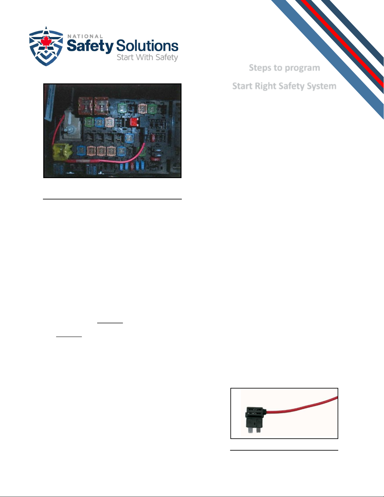
3) Locate fuse box and use a fuse adapter like, or similar, to
the one on this page (gure 3) which is a Blade Fuse Add
-A-Circuit Pigtail.
4) Determine a 12 volt switched power connecon to use.
5) Pull switched power fuse and replace with the blade
fuse add-a-circuit shown in gure 4.
6) Make connecon with Red wire from harness supplied
with unit.
7) Connect block wire from wire harness supplied to a good
and clean ground point.
8) Place data logger and extra wire together under the
driver’s dashboard with zap straps or equivalent.
Any concerns please contact—suppo[email protected]
Once you have chosen the locaon for the Sys-
tems tags on our equipment and installed the
data logger you must now program the system
to recognize your tags. This is quick to do and
can be completed in
several easy steps:
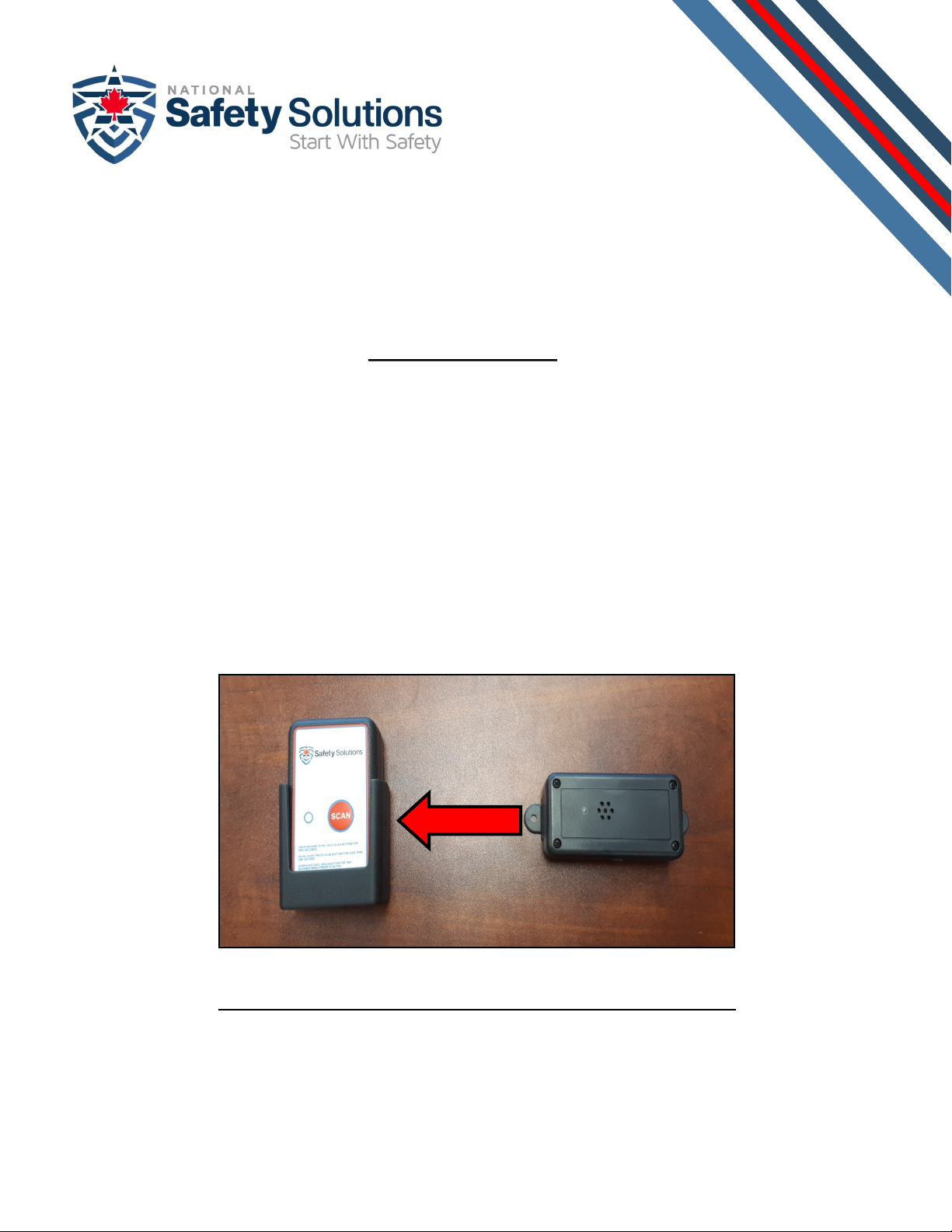
1) On the handheld scanner, press and hold the SCAN
buon for 5 seconds. The system will beep twice, and
a red LED will start ashing. You are now ready to
program the system.
2) Perform your 360° walk around while scanning the
tags. You will noce as you scan the tags that the red
LED will change to green and will quickly ash to indi-
cate the amount of tags that have been scanned. For
example, 3 quick green ashes would indicate that
three tags have been scanned.
3) Once all the tags have been scanned press the SCAN
buon once. You will hear three beeps and the green
LED will change to blue. This indicates that the scan-
ner is ready to communicate with the data logger.
4) You can now power your equipment, and the alarm
will start. Aer 5-10 seconds, the alarm will change
tones, beep 4 mes and then stop. This indicates that
the programming was successful and ready for use.
Informaon
Steps to program
Start Right Safety System
Figure 3 - Fuse Box
Figure 4 - Fuse Adaptor

July 1st 2019 Rev 2 Visit our site www.nsslca.com for more informaon! 4
Important
Figure 5 - Bluetooth Connectivity
>2
*IMPORTANT*
When mounng the Scanner Holder/Case ensure
it is 24” or less from where the Data Logger has
been mounted as shown in gure 5. This will
ensure the low frequency signal to promptly
complete the wireless communicaons.

July 1st 2019 Rev 2 Visit our site www.nsslca.com for more informaon! 5
Suggested RFID Tag Placement
Placement
1) Remove handheld scanner from scanner holder, press buon once and hold for two seconds ll you hear
the scanner beep twice and the light ash red.
2) Now begin the 360 degree walkaround in accordance with the procedure developed by your company.
3) Scan system tags with handheld scanner as walkaround is performed. No need to press the scan buon at
each inspecon locaon, only bring the scanner within 1/4” of system tags.
4) Return handheld scanner to the scanner holder next to the datalogger. To ensure that all system tags have
been scanned, 3 short beeps from the scanner will be heard.
5) Start the vehicle/equipment and wait for the system to receive data from the scanner to ensure a full scan
has been completed. Once the system receives data from the scanner (around 5-10 seconds), the alarm will
be disabled and the vehicle/equipment is ready to use.
Figure 2 - c
Figure 2 - a
Figure 2 - b
Table of contents
Popular Safety Equipment manuals by other brands

SKYLOTEC
SKYLOTEC MAT-BA-0140-00 Instructions for use

Horizon Signal
Horizon Signal SQ2-T user manual

Safety Xpress
Safety Xpress BOLSM90X PRODUCT INFORMATION & INSTALLATION GUIDE

Storch
Storch Craftsman sun operating instructions

Micro Detectors
Micro Detectors LS2 Series Installation and operation manual

DBI SALA
DBI SALA ROLLGLISS R550 User instruction manual