manuals.online logo
Brands
  1. Home
  2. •
  3. Brands
  4. •
  5. ABB
  6. •
  7. Safety Equipment
  8. •
  9. ABB XT230RS/DALI Manual

ABB XT230RS/DALI Manual

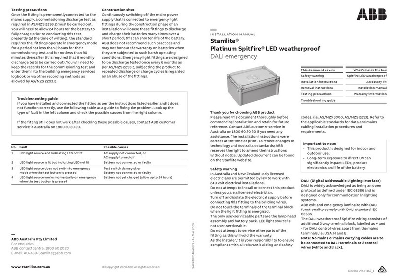
Power Supply Emergency Duration
Power Consumption Protection Class
Ambient Operating Temp IP Rating
Charge Time Function
Operation Installation
and non-maintained Viewing distance
XT230RS/DALI
Technical Specifications
1 of 4
4 of 4
: 3 Hours
: II
: IP20
: DALI
: Wall mount or Ceiling mount
: 30m
: 220-240VAC, 50/60 Hz
: Max. 3.5W
: -5°C...+45°C
: 24 Hours
: Maintained
Note: We reserve the right to make technical changes
or modify the contents of this document without prior
notice. With regard to purchase orders and/or contracts,
the agreed particularsshall prevail. ABB does not accept
any responsibility whatsoever for potential errors or
possible lack of information in this document.
We reserve all rights in this document and in the subject
matter and illustrations contained therein.
Any reproduction, disclosure to third parties or utilisation
of its contents - in whole or in parts -is forbidden without
prior written consent of ABB.
Copyright © 2020 ABB
All rights reserved
Instruction Leaflet
Model Number
Explanations
Maintained
Luminaire
Switched Maintained
Luminaire
Non-maintained
Luminaire
Emergency mode
Failure-Battery
Charge
Input
Voltage
220-240V~
50/60HZ
Charge
Duration
Discharge
Duration Battery Power
Ni-Mh
3.6V 2.0Ah
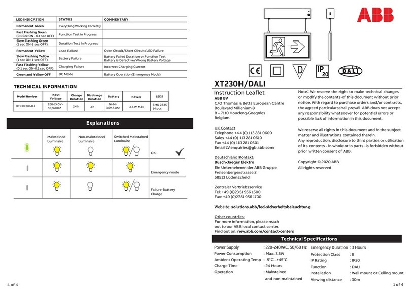
LED INDICATION STATUS COMMENTARY
Permanent Green
Everything Working Correctly
Fast Flashing Green Function Test in Progress
(0.1 Sec ON - 0.1 sec OFF)
Slow Flashing Green
(1 sec ON-1 sec OFF) Duration Test In Progress
Permanent Yellow Load Failure
Slow Flashing Yellow Battery Failure
(1 sec ON-1 sec OFF)
(0.1 sec ON-0.1 sec OFF) Charging Failure
DC Mode
Green and Yellow OFF
Open Circuit/Short Circuit/LED Failure
Battery Failed Duration or Function Test
Battery is Defective/Wrong Battery Voltage
Incorrect Charging Current
Battery Operation(Emergency Mode)
Fast Flashing Yellow
OK
3.5 W Max
3 h
24 h
TECHNICAL INFORMATION
XT230RS/DALI
LEDS
SMD 2835
14 pcs
IP
20
D
ABB BV
C/O Thomas & Betts European Centre
Boulevard Millenium 8
B – 7110 Houdeng-Goegnies
Belgium
UK Contact
Telephone +44 (0) 113 281 0600
Sales +44 (0) 113 281 0610
Fax +44 (0) 113 281 0601
Email LV[email protected]
Deutschland Kontakt:
Busch-Jaeger Elektro
Ein Unternehmen der ABB Gruppe
Freisenbergerstrasse 2
58513 Lüdenscheid
Zentraler Vertriebsservice
Tel: +49 (0)2351 956 1600
Fax: +49 (0)2351 956 1700
Website: solutions.abb/led-sicherheitsbeleuchtung
Other countries:
For more information, please reach
out to our ABB local contact center.
Find out on: new.abb.com/contact-centers
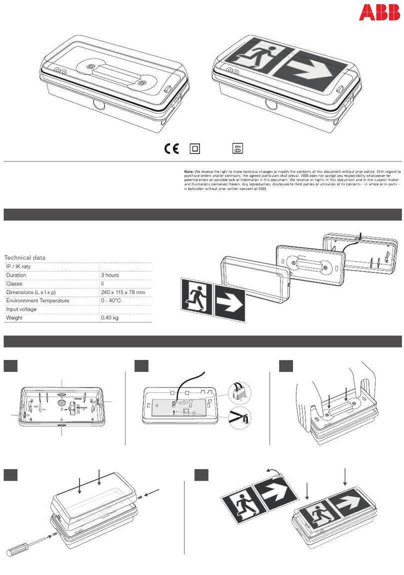
MOUNTING INSTRUCTIONS
3 of 4
2 of 4
WIRING INSTRUCTIONS
Connect the AC supply wire to terminal block. Refer to wiring
instruction showed below.
Connect battery male and female connector inside of mounting
bracket.
Remove the pictogram on the unit, select other pictogram you need
then insert into slot of panel.
Snap AC supply on PCBA and then snap fixture to mounting
plate.
Suitable cable 0.75-2.5mm²
Wiring connection Connect battery
Change pictogram when necessary Finish installation
Non-Maintained Wiring Maintained Wiring
Maintained (default operation):
Connect L,N and leave jumper cable connected.
Non-maintained:
Connect L,N and remove jumper cable.
Dispart mounting plate Wall mounting or Ceiling mounting
Knock out appropriate center cable entry hole and mounting screw
hole on the mounting plate.
Route AC supply wire through center hole of mounting plate.
Fix mounting plate on the mount surface with screws and anchor nuts.
Insert flat screwdriver into slot on side of unit, pry off and remove
the mounting plate from unit.
Disconnect AC connector from PCBA.
a
b
a
b
c
Mounting plate
MOUNTING OPTIONS
Wall mounting Ceiling mounting
PICTOGRAM STYLES
PRECAUTIONS
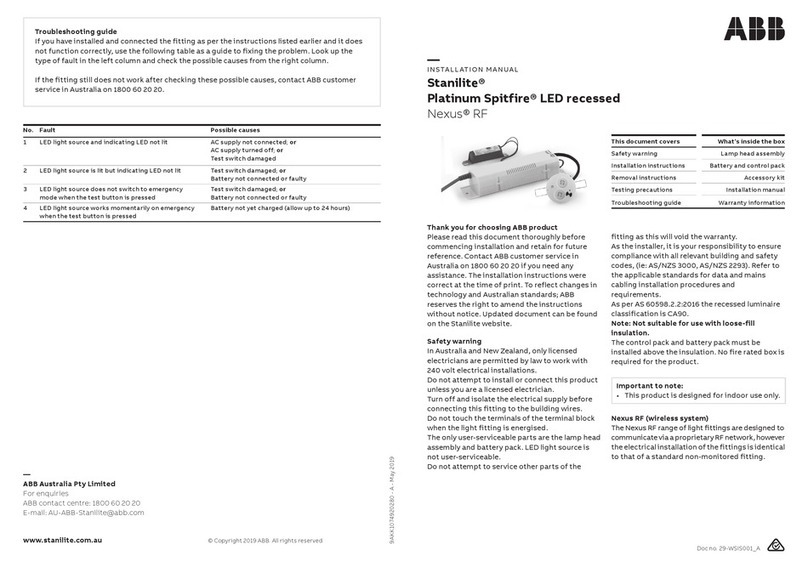
Carefully read this instruction leafet before installing or using the luminaire.
This leafet provides important information about the correct installation, use, maintenance and disposal
of this product. Please observe the following guidelines:
1. Installation must be in accordance with European installation requirements HD 60364 and additional local
regulations.
2. This product may not be modified in any way what so ever or used for a purpose or in an environment
other than for which it is designed. Failing to observe these guidelines will invalidate the warranty and the
CE-compliance of this product.
3. The luminaire is suitable for indoor use only
4. Before installing the luminaire, the supply must be isolated.
5.The luminaire should be connected to the voltage equivalent to that indicated on the type label
SERVICE & OPERATION
Normal Operation: The green indicator light on face plate stays on. The LED will go out if the mains supply
fails, the internal charger malfunctions, or the unit is in test mode.
Battery: Sealed Ni-Cad or Ni-Mh rechargeable battery pack. Battery should be replaced when the required
duration is no longer achieved. To avoid any damage to the fixture and ensure its performance, the battery
should be replaced with same brand and type.
Test Switch: Press the test switch button, LED indicator will go out and the sign will be illuminate from its
battery pack.
WARNING:
The luminaire must, under no circumstances, be covered with insulating material or similar material only
Commissioning Test Behaviour
Initial connection of the mains supply will initiate a commissioning sequence where the battery will remain on
charge and test for an uninterrupted 60 hours. Any interruption of the mains supply during this period will reset
the counter to zero.
The sequence is : to charge for 24hours. Having fully charged the battery, then execute a duration test.
Upon successful completion of the duration test, the gear will perform another full charge period of 24hours.
After this period, it is suggested to perform a function test and then check for successful completion
of the function and duration tests.
Therefore, after initial mains power on, it is best to leave the gear alone for 60 hours to allow the gear
to complete its pre-programmed commissioning testing. During the 60 hour period, any attempt
to have the gear perform a function or duration test will simply result in the requested test being 'pended'.
Following the commissioning test it will then perform whatever tests are pended. Meaning that if you had
pressed "start duration test", at the end of commissioning, the gear will perform another duration test and
another subsequent charge period before normal operations could be resumed.
Gear Behaviour After Battery Change (meaning Disconnect / Reconnect battery)
After changing the battery, the gear will perform a complete commissioning sequence, as described above,
irrespective of the condition of the battery.
Function test
A 5 second functional test is carried out at nominally 1 week interval.
Duration test
The gear switches to battery supply with mains supply off, and runs until the batteries can no longer supply
the lamp
The length of time to run out is recorded in memory.
A pass result indicates the battery powered the fitting and lamp for the rated period of this fitting.
A full rated duration test is carried out nominally at 52 weeks intervals.
In DALI mode, the start of the regular duration and function tests, is initiated by the attached controller.
If the DALI controller is not available, the gear will revert to its automated settings.
Ceiling mounting
Wall mounting
DALI Connection
Battery Connection
AC connector
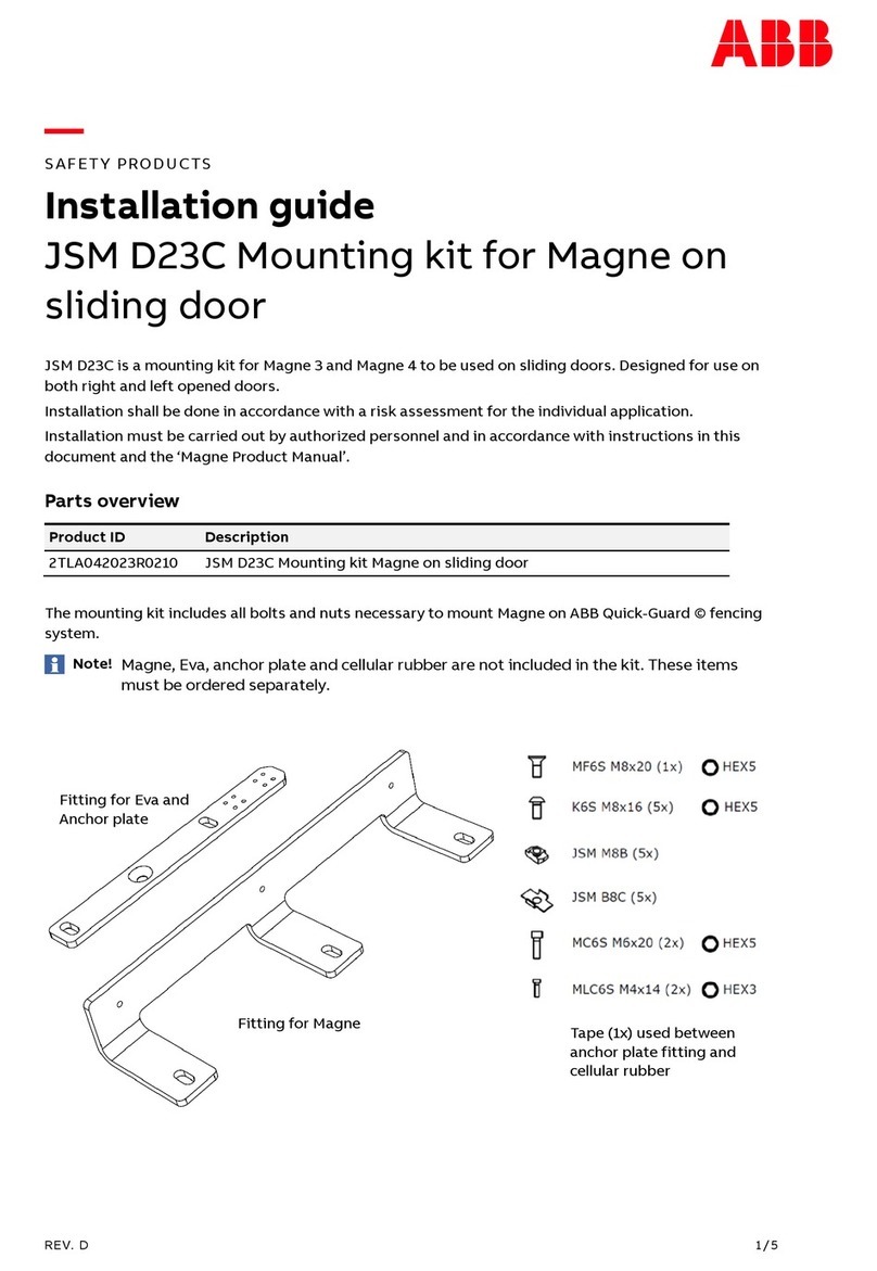
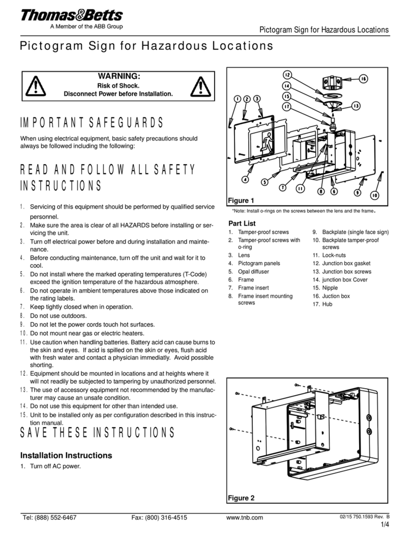
Other ABB Safety Equipment manuals

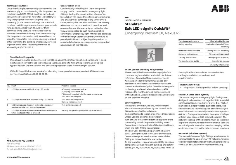
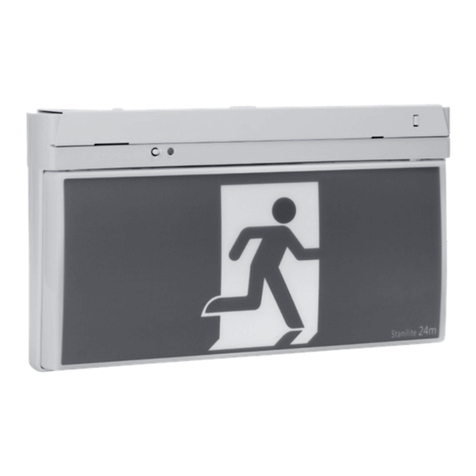
ABB Stanilite Exit LED edgelit Quickfit User manual

ABB

ABB Stanilite Exit LED edgelit Quickfit User manual

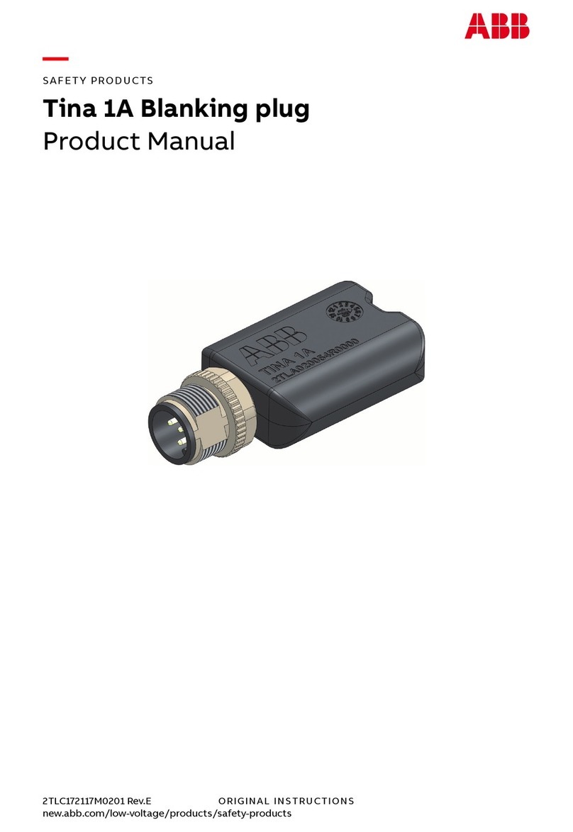
ABB Tina 1A User manual

ABB

ABB Tina 1A User manual

ABB SafeMove2 Instructions for use

ABB

ABB SafeMove2 Instructions for use

ABB HD5-S User manual

ABB

ABB HD5-S User manual

ABB jokab safety Smile 11EA Tina User manual

ABB

ABB jokab safety Smile 11EA Tina User manual

ABB XT230H/DALI Manual

ABB

ABB XT230H/DALI Manual

ABB Stanilite Platinum Spitfire LED weatherproof User manual

ABB

ABB Stanilite Platinum Spitfire LED weatherproof User manual

ABB PrimEvo XT100E Manual

ABB

ABB PrimEvo XT100E Manual

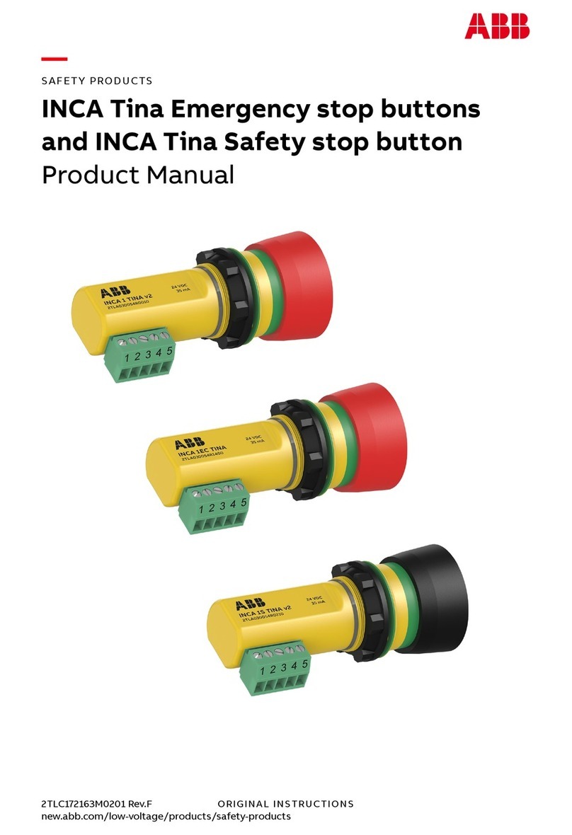
ABB INCA 1EC Tina User manual

ABB

ABB INCA 1EC Tina User manual

ABB Thomas & Betts RH Series User manual

ABB

ABB Thomas & Betts RH Series User manual

ABB Jokab Safety Safeball JSTD1 User manual

ABB

ABB Jokab Safety Safeball JSTD1 User manual

ABB Welcome User manual

ABB

ABB Welcome User manual

ABB Nexus RF User manual

ABB

ABB Nexus RF User manual

ABB JSM D23C User manual

ABB

ABB JSM D23C User manual

ABB Stanilite Spitfire Standard User manual

ABB

ABB Stanilite Spitfire Standard User manual

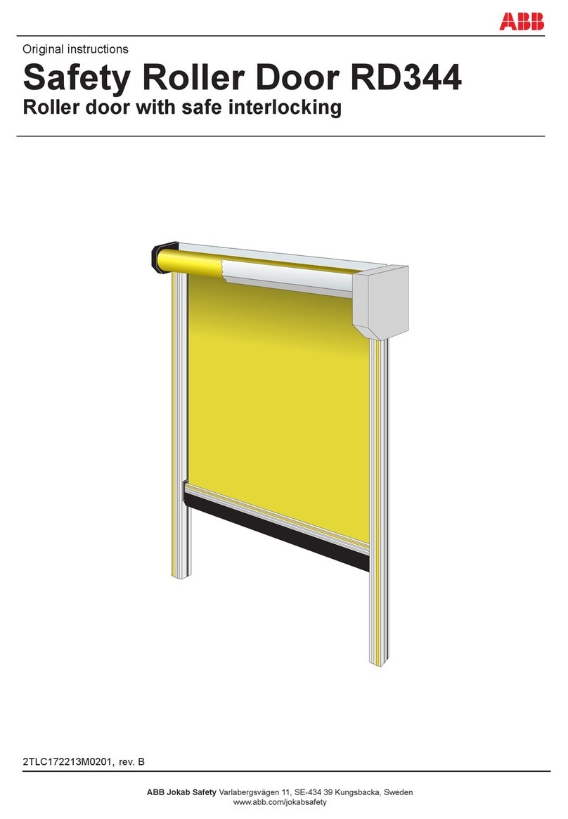
ABB RD344 User manual

ABB

ABB RD344 User manual

ABB Stanilite Platinum exit LED Quickfit User manual

ABB

ABB Stanilite Platinum exit LED Quickfit User manual

Popular Safety Equipment manuals by other brands

KRATOS SAFETY FA 10 901 00 operating instructions

KRATOS SAFETY

KRATOS SAFETY FA 10 901 00 operating instructions

Glasdon Signmaster Ultra Installation and maintenance instructions

Glasdon

Glasdon Signmaster Ultra Installation and maintenance instructions

ABS Safety UniGlide PRO manual

ABS Safety

ABS Safety UniGlide PRO manual

Crye Precision RANGE BELT Operator's manual

Crye Precision

Crye Precision RANGE BELT Operator's manual

Carl Stahl Kromer 7200 operating instructions

Carl Stahl Kromer

Carl Stahl Kromer 7200 operating instructions

DELTA PLUS Deltatek 5000 DT117 use instructions

DELTA PLUS

DELTA PLUS Deltatek 5000 DT117 use instructions

pizzato CS MP301 0 Series manual

pizzato

pizzato CS MP301 0 Series manual

Jippie's 83683 quick start guide

Jippie's

Jippie's 83683 quick start guide

Sealey WORKSAFE SSP1.V6 manual

Sealey

Sealey WORKSAFE SSP1.V6 manual

Guardian Fall Protection Halo Web SRL instruction manual

Guardian Fall Protection

Guardian Fall Protection Halo Web SRL instruction manual

MEDC SM87BG Technical manual

MEDC

MEDC SM87BG Technical manual

A.HABERKORN KS 45 INSTRUCTIONS FOR USE AND TEST MANUAL

A.HABERKORN

A.HABERKORN KS 45 INSTRUCTIONS FOR USE AND TEST MANUAL

Knauf SHAFTLINER MOULDSTOP Installation

Knauf

Knauf SHAFTLINER MOULDSTOP Installation

TRQ EYE-3W manual

TRQ

TRQ EYE-3W manual

Spencer Logic user manual

Spencer

Spencer Logic user manual

STI SA5600 Installation

STI

STI SA5600 Installation

Coba COBAelite ESD Installation guidelines

Coba

Coba COBAelite ESD Installation guidelines

AUSTRIALPIN FISH operating instructions

AUSTRIALPIN

AUSTRIALPIN FISH operating instructions

manuals.online logo
manuals.online logoBrands
  • About & Mission
  • Contact us
  • Privacy Policy
  • Terms and Conditions

Copyright 2025 Manuals.Online. All Rights Reserved.