Max 2
Viti M6
MT=0.7Kgm
(5 Ftlbs)
(fig. D1) (fig. D2)
P.177ø4 mm
P.174 P.91
P.18
P.175
P.176
P.131
P.132
P.177ø8 mm
P.70
P.70n
P.99
P.309
P.70 bis
P.130
PRIMA Industries Srl
Via Pio La Torre, 6
42015 Correggio (RE) Italy
Tel. +39 0522 637 583 - Fax +39 0522 641 682
PRIMA industries:
Automotive division
Cod.40552
Rev. 4 16/01/2017
- Per mantenere una buona estetica della maniglia nel tempo, evitare il contatto con cere per carrozzerie e
con idrocarburi (nafta, benzina, ecc.).
- Durante le operazioni di montaggio/smontaggio e le manutenzioni ordinarie, si consiglia di attenersi alle
norme di sicurezza previste (D. Lgs 81/2008) e di utilizzare abbigliamento adeguato (camici,occhiali, guanti,
ecc.).
- Ingrassare la serratura ogni due mesi con grasso Tribol 4020 - 460 - 2 a base minerale.
- La ditta non assume nessuna responsabilità nè rilascia alcuna garanzia se il prodotto viene inserito in
sistemi o montato con particolari che non siano di produzione della ditta stessa. La ditta si ritiene svincola
ta da qualsiasi indennizzo eventualmente richiesto dall’acquirente per danni subiti o arrecati a terzi.
AVVERTENZE
VERSIONE PNEUMATICA
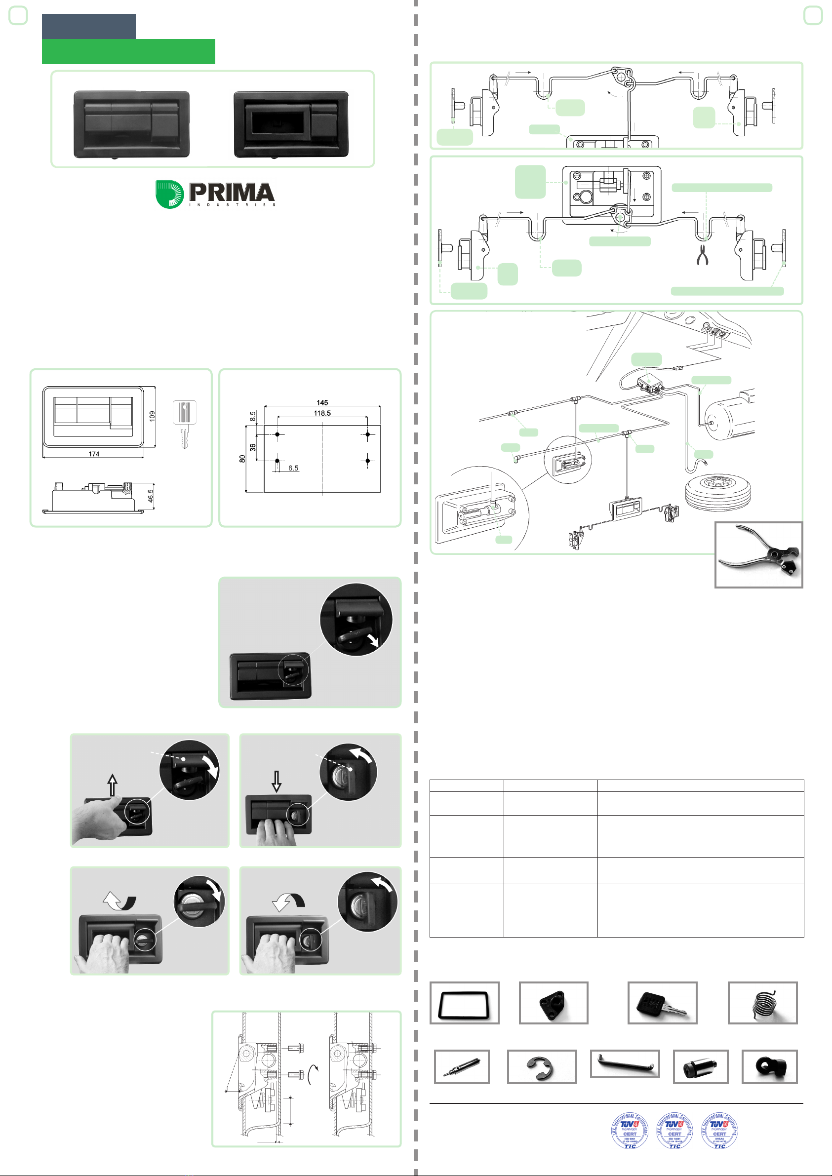
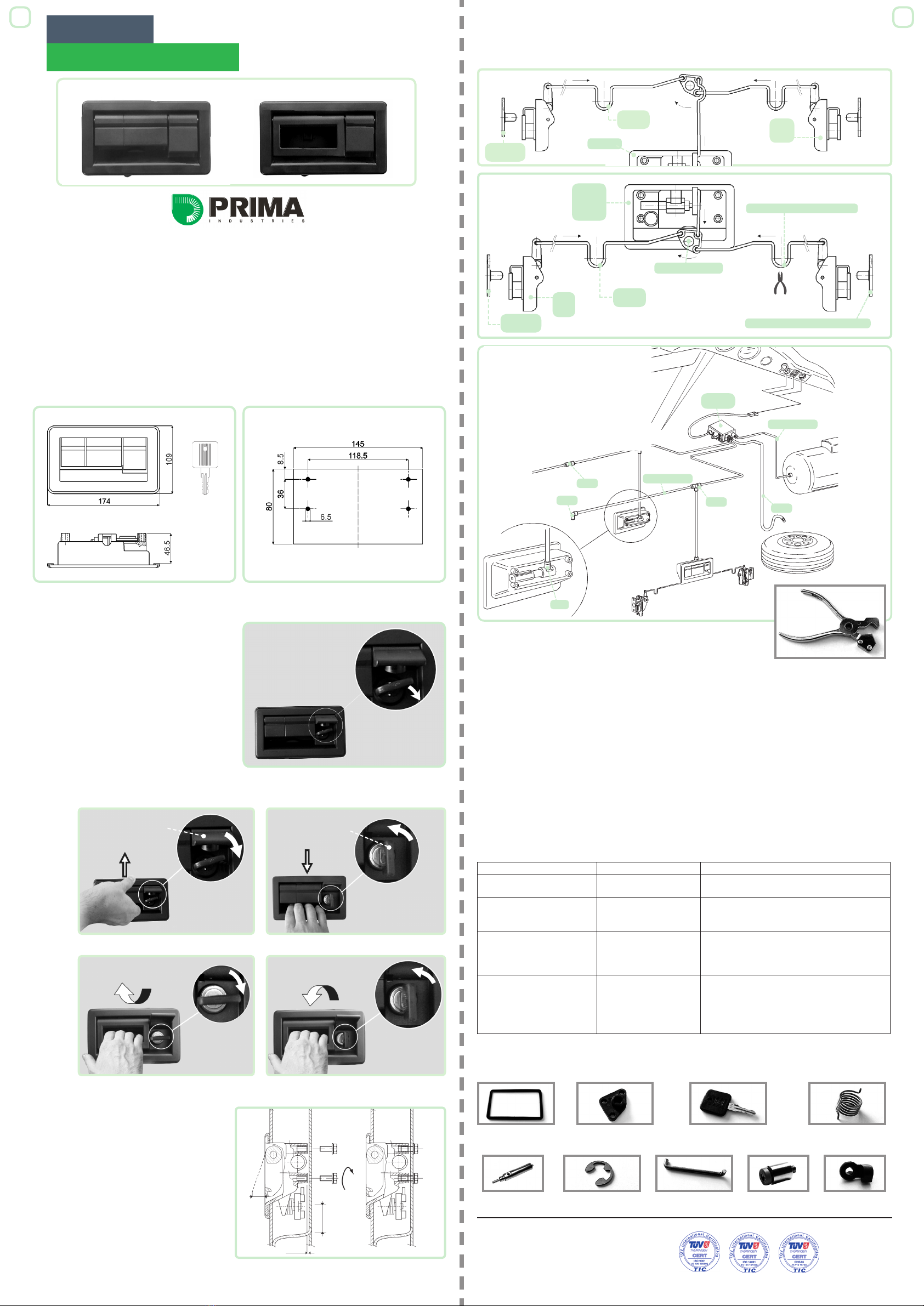
5 (Solo per maniglie Pneumatiche) - Collegare
tubo in Rilsan P.177 di Ø 4mm (tagliato con
apposite forbici a lama di cutter per evitare
ovalizzazioni o bave - vd. fig.F) al raccor-
do P.18 fissato sul cilindro pneumatico (vd.
fig.G). Collegare il terminale libero del tubo
ai raccordi P.174, P.175, e P.176 dell’impianto
pneumatico dell’autobus.
(fig. G)
Le maniglie possono essere fornite in tre modelli: M (manuale), PN (pneumatica), E (elettrica); le dimensioni
d’ingombro e di fissaggio nei tre casi sopracitati sono identiche (vedi fig.A e fig. B).
Questo manuale tratta i primi due modelli (per maggiori informazioni riguardo la versione E, contattare
l’ufficio commerciale).
Verificare se la serratura é già inserita nell’apposita
sede (sotto lo sportello di protezione). In mancanza di
serratura, siete in possesso della versione J.O.K. quin-
di seguire le indicazioni nel manuale utente cod.40712
contenuto in questa confezione. La Prima Industries
Srl declina ogni responsabilità nel caso in cui non
vengano rispettate le istruzioni riportate nel suddetto
documento: tale inadempimento potrebbe rendere
inutilizzabile la maniglia. In presenza di serratura per
liberare il meccanismo di funzionamento, la chiave
deve essere in posizione orizzontale (vedi fig.C)
Nelle maniglie pneumatiche, l’apertura / chiusura è
comandata:
a) dalla plancia comandi dell’autista che aziona una
centralina elettro-pneumatica P.131 o P.132;
b) con chiave d’emergenza direttamente sulla
maniglia.
La chiave riporta il codice di riconoscimento grazie al
quale è possibile richiedere ricambio alla ditta PRIMA
in caso di smarrimento.
P119
P141
1 - Assicurarsi che la guarnizione aderisca al
profilo della maniglia e collocare quest’ultima
nell’apposita sede del portellone ( l’utilizzo di
silicone adesivo o di altri collanti generalmente
impiegati non danneggia la guarnizione).
2 - Allineare i fori di fissaggio ai corrispondenti
creati nel portellone seguendo le indicazioni della
dima di foratura (assicurarsi che vengano rispettate
le condizioni riportate in fig.D/1).
3 - Fissare la maniglia al portellone utilizzando
quattro viti M6 (viti e rondelle non sono comprese
nella confezione). Stringere le viti ad una coppia
di serraggio max di 0.7 Kgm - 5 Ftlbs ( dopo il
serraggio delle viti, le boccole della maniglia devo-
no appoggiare sulla lamiera interna dello sportello
vd. fig.D/2).
4 - Applicare le aste di collegamento P.99 o P309 alle serrature P.70 ed alla camma. Le aste hanno un senso
(destro e sinistro) ed è possibile tararne la lunghezza agendo sulle pieghe di registro (vd. fig.E2).
Solo le maniglie P.141 possono aprire N° 4 P.70 installando una seconda camma e collegandola al 2° foro
dell’impugnatura(vd. fig.E1)
dima di foratura
(fig.A) (fig. B)
(fig. C)
Sportellino di protezione
Chiave
Min 50
P.70
P.70n
P.70 bis
P.130
P.99
P.309
P.119
P.141
P.178
P.183
Camma
Piega di registro
Perno di riscontro
(fig. E2)
(fig. E1)
1 - Smontare le aste di collegamento dalla camme di azionamento liberandole dal giunto P.94.
2 - Allentare e rimuovere le quattro viti di montaggio M6.
3 - (Valido solo per versione PN) Controllare preventivamente di avere chiuso l’impianto pneumatico. Per
liberare il tubo in Rilsan, schiacciare l’anello arancione del raccordo verso il cilindretto, ed estrarre il tubo.
4 - Estrarre il corpo maniglia dallo sportello.
RICAMBI PER P.119 - P.141
DESCRIZIONE
FUNZIONAMENTO DI BASE
MONTAGGIO
SMONTAGGIO
6 - Controllare il corretto collegamen-
to dei tubi alla centralina pneumatica
(P.131 o P.132).
7 - Azionare la maniglia per verificare
che i collegamenti funzionino senza
intralci.
Chiudere ed aprire più volte il
portellone come collaudo finale.
Per ulteriori informazioni si prega di contattare il nostro Ufficio Commerciale
Nel caso di eventuali contestazioni di prodotto, citare sempre il codice e il n° del lotto indicato sul sovrapacco
N.B.: - La ditta non assume nessuna responsabilità nè rilascia alcuna garanzia se il prodotto viene inserito in
sistemi o montato con particolari che non siano di produzione della ditta stessa.
- Evitare l’uso frequente della chiave d’emergenza; utilizzarla esclusivamente in casi di estrema necessità
onde evitare eventuali danneggiamenti dell’impianto.
- Carico di rottura impugnatura = 2.000 N • Temperatura di esercizio -10/+120 °C
Cod.60228:
Guarnizione Cod.67027:
Camme Cod.67017:
Molla per camme
P74 - Cod. Chiave: comunicare all’UC
PRIMA il numero inciso sulla chiave
P15-Cod.69367:
Cilindro pneumatico Cod.60795:
Anello d’arresto Cod.64645: Asta di
collegamento camme P94-Cod.65437:
Giunto
P18-Cod.69377:
Raccordo
Apertura portellone Chiusura portellone
Apertura portellone
Sportellino di protezione
Chiusura portellone
Chiave
P.119 P.141
P.141
Maniglie
P.119 P.141
(fig. F)
INDIVIDUAZIONE GUASTI
SINTOMO PROBLEMA POSSIBILE SOLUZIONE
Il corpo maniglia si muove
durantel’apertura e la chiusura Maniglia allentata Verificare il carico di serraggio delle viti M6
(punto3delmontaggio).
La serratura non ruota in apertura
Chiave non compl. inserita
(vedi anche istruzioni JOK)
- Copriserratura non
completamente inserito.
- Sfilare e riinfilare la chiave controllando l’eventuale
presenza di bave.
- Spingere il copriserratura fino a contro la battuta.
L’apertura funziona con difficoltà
Lunghezza aste
Allineamento serratura,
pernodi riscontro.
- Regolare la lunghezza delle aste agendo sulla piega
diregistro (punto 4)
- Controllare l’allineamento della serratura e del perno di
riscontro ed eventualmente regolare il perno di riscontro.
Il circuito non rimane in pressione
(valido solo per la maniglia a
funzionamento pneumatico).
Il cilindro o il suo raccordo
perdono aria.
Individuare perdita (inserire maniglia in acqua).
a) Perdita aria dal raccordo: sfilare tubo ed interstarlo
con forbici (fig. M); svitare raccordo, inserire goccia d’olio
nel filetto del cilindro e riavvitare. Se il problema persiste,
sostituire il raccordo con ricambio PRIMA.
b) Perdita aria dal cilindro: sostituire con ricambio PRIMA.
12
Questo prodotto è conforme alle seguenti norme vigenti: UN ECE R107/06; Direttiva 2000/53/CE; Direttiva 2003/11/CE; UN ECE
R118.2; FMVSS 302; ROHS; REACH; GADSL; PAH; CONFLICT MINERALS RULES. Lo smaltimento del particolare deve essere
effettuato in conformità alla Direttiva 2000/53/CE e alle leggi vigenti dello Stato in cui esso avviene, facendo attenzione ai simboli
di riciclaggio presenti (dove possibile) sui singoli componenti. Lo smaltimento abusivo del prodotto da parte dell’utente comporta
l’applicazione delle sanzioni amministrative previste dalla normativa nazionale vigente. La raccolta separata e il riciclo consentono di
ridurre i consumi di risorse naturali, oltre che salvaguardare l’ambiente e tutelare la salute umana.