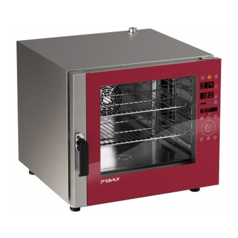
Primax EASY LINE Quick start guide

1
MANUALE ISTRUZIONI D’INSTALLAZIONE, USO E MANUTENZIONE
INSTALLATION USE AND MAINTENANCE INSTRUCTIONS
INSTALLATIONS-, GEBRAUCHS- UND WARTUNGSANLEITUNG
MANUEL D'INSTRUCTION D'INSTALLATION, D'UTILISATION
ET D'ENTRETIEN
EASY LINE
FORNI ANALOGICI, ELETTRICI E A GAS,
A CONVEZIONE E CONVEZIONE-VAPORE
PER GASTRONOMIA E PER PASTICCERIA
CONVECTION AND CONEVCTION-STEAM, ELECTRIC AND GAS, ANALOGIC OVENS
FOR GASTRONOMY AND FOR PASTRY
ELEKTRO- UND GASÖFEN KONVEKTION, HEISSLUFTDAMPF, MIT ANALOGER
STEUERUNG
FÜR DIE GASTRONOMIE UND FÜR KONDITOREI
FOURS ANALOGIQUES, ELECTRIQUES ET À GAZ, À CONVECTION ET CONVECTION ET
VAPEUR
POUR GASTRONOMIE ET POUR PÂTISSERIE
8710020_EASY-da matricola n°/from serial n° 150225003- a/to………………….

2
Il costruttore si riserva il diritto di apportare modifiche alle caratteristiche tecniche e funzionali dei prodotti
presentati in questa pubblicazione senza dare alcun preavviso; inoltre, non risponde di possibili inesattezze,
imputabili ad errori di stampa o di trascrizione, contenute nel presente libretto.
All specifications of this handbook are not binding and the manufacturer could change them
without notice; the manufacturer declines any liability for possible misprints.
Der Hersteller behält sich vor, die technischen und betrieblichen Merkmale der Erzeugnisse, die in dieser
Veröffentlichung vorgestellt werden, ohne Vorabhinweis zu verändern. Darüber hinaus haftet er nicht für
Unstimmigkeiten, die auf Druck- oder Übertragungsfehler in diesem Heft zurückzuführen sind.
Le fabricant se réserve le droit d'apporter des modifications aux caractéristiques techniques et fonctionnelles des
produits présentés dans cette publication sans aucun préavis ; en outre, il n'est pas responsable de possibles
erreurs, imputables à des erreurs d'impression ou de transcription, contenues dans le manuel présent.
INDICE GENERALE- GENERAL INDEX- INHALT- SOMMAIRE
ITALIANO 3
ENGLISH 12
DEUTSCH 22
FRENCH 32
ITALIANO
Indice
1. AVVERTENZE 3
2. CARATTERISTICHE TECNICHE GENERALI 4
3. AVVERTENZE PER L’ INSTALLATORE 5
4. PANNELLO DI CONTROLLO E LEGENDA 9
5. INDICAZIONI PER L’UTENTE FINALE 11
6. SPEGNIMENTO 11
7.PROBLEMI E SOLUZIONI 11
8. MANUTENZIONE ORDINARIA 11
9. SMALTIMENTO DELL’IMBALLO 11
10.DISMISSIONE E ROTTAMAZIONE DELL’APPARECCHIATURA 11
11. SCHEMA INSTALLAZIONE 42
12. SCHEMI ELETTRICI 44
13. CE 60

3
1. AVVERTENZE
1.1. AVVERTENZE GENERALI
Il presente manuale è stato realizzato per permettere una corretta installazione, messa a punto e manutenzione dell'apparecchiatura. E’ di
fondamentale importanza che le avvertenze contenute nel presente libretto siano lette attentamente in quanto forniscono importanti
indicazioni circa la sicurezza d'installazione, d'uso e di manutenzione.
Il presente manuale e lo schema elettrico devono essere conservati con cura e messi a disposizione dell'operatore (installatore, tecnico ed anche
utilizzatore finale) per ogni ulteriore consultazione.
L'apparecchio deve essere installato, collaudato e assistito da personale qualificato in possesso dei requisiti di legge.
L'apparecchiatura è stata progettata e realizzata per la cottura di prodotti alimentari e per la rigenerazione di alimenti congelati o surgelati, dovrà
pertanto essere destinata solo all'uso per il quale è stata espressamente concepita.
Qualsiasi impiego diverso da quello specificato non comporta per il costruttore impegno o vincolo d'alcun genere.
Viene declinata ogni responsabilità del produttore con decadimento della garanzia in caso di modifiche elettriche e/o meccaniche.
Manomissioni in genere non espressamente autorizzate e che non rispettino quanto riportato nel presente manuale, fanno decadere la garanzia.
Per l'eventuale riparazione rivolgersi esclusivamente ad un centro di assistenza tecnica autorizzato dal costruttore e richiedere l'utilizzo di
ricambi originali.
In caso di dubbio non utilizzare l'apparecchiatura e rivolgersi a personale professionalmente qualificato. Il mancato rispetto di quanto sopra può
compromettere la sicurezza dell'apparecchiatura.
Osservare le norme di sicurezza locali vigenti al momento dell'installazione.
Verificare che le caratteristiche della rete elettrica siano conformi ai dati riportati sulla targhetta matricolare.
Il materiale di imballaggio (sacchetti in plastica, polistirolo espanso, chiodi, ecc.) in quanto potenziale fonte di pericolo deve essere tenuto fuori
dalla portata dei bambini e correttamente riciclato secondo le norme locali in vigore.
1.2. AVVERTENZE TECNICHE GENERALI
- Ogni apparecchiatura è dotata di una targhetta caratteristiche, posta sul lato destro, in basso, che ne identifica il modello e i dati tecnici
principali : LEGGERE I DATI RIPORTATI PRIMA DELL’INSTALLAZIONE.
- L’apparecchiature deve essere installata in un locale aerato e ventilato.
- L’apparecchiatura deve essere adoperata solo da personale adeguatamente formato.
- Tenere lontani i bambini dall’apparecchiatura.
-Se dopo aver posizionato l'apparecchio sul suo supporto la parte più alta supera l'altezza di 1,60 m, è necessario apporre l’adesivo che trovate
insieme alla documentazione fornita insieme all’apparecchiatura:
- L’utilizzo dell’apparecchiatura richiede sorveglianza costante.
Quando il forno è in funzione fare attenzione alle superfici esterne che si riscaldano: evitare di toccarle.
- Chiedere all’installatore l’installazione di un addolcitore d’acqua: in caso di mancanza l’apparecchiatura potrebbe essere danneggiata
gravemente dal calcare.
- Si consiglia l’installazione di un sifone in corrispondenza dell’uscita dell’acqua di scarico del forno.
1.3. AVVERTENZE D’UTILIZZO GENERALI
Al primo utilizzo:
- In fase di primo utilizzo, fare attenzione che il libretto istruzioni, sacchetti di plastica e altri oggetti siano stati tolti dalla camera di cottura del
forno.
- Al primo utilizzo del forno si consiglia di farlo funzionare a vuoto per 30-40 minuti ad una temperatura di 200° C, così da eliminare odori
sgradevoli di materiali usati per isolamenti termici o altri residui di lavorazione.
La pulizia:
- Prima di accendere il forno, per la prima volta, pulire accuratamente la camera di cottura utilizzando prodotti non corrosivi (alcalini) per non
danneggiare le superfici.
- Evitare di utilizzare materiali e prodotti abrasivi per non graffiare le superfici.
- Alla fine dell’utilizzo quotidiano pulire l’interno della camera di cottura e l’esterno dell’apparecchiatura: questo prolungherà la durata
dell’apparecchiatura e ne assicurerà il buon funzionamento.
- Non utilizzare getti d’acqua in pressione per la pulizia del forno.
- Evitare operazioni di salatura all’interno della camera di cottura per non avere incrostazioni o depositi di sale. In caso di depositi risciacquare
immediatamente ed asciugare con cura.
Precauzioni d’uso:
- Per evitare bruciature, non utilizzare contenitori riempiti con liqudi o cibi che possono diventare fluidi con la cottura, nei livelli diversi da quelli
che possono essere facilmente osservati.
- Dopo aver cucinato a vapore aprire con cautela la porta del forno, per evitare d’entrare in contatto improvviso e diretto con il vapore ad alta
temperatura, rimasto in camera di cottura.
- Il non rispetto di questa precauzione potrebbe essere molto dannoso per l’operatore.
- E’ vietato ostruire le prese d’aria e tutte le altre aperture esistenti sul forno, in caso contrario si - comprometterà il funzionamento in sicurezza
dell’apparecchiatura.
- Per evitare bruciature, non utilizzare contenitori riempiti con liquidi o cibi che possono diventare fluidi con la cottura, nei livelli diversi da quelli
che possono essere facilmente osservati.
Guasto e dismissione:
- Disattivare l'apparecchiatura in caso di guasto o di cattivo funzionamento.
- In caso di dismissione dell’apparecchiatura interrompere e scollegare le linee di alimentazione gas (ove presenti), energia elettrica ed acqua.

4
1.4. TARGHETTA DATI TECNICI GENERALI FORNI ELETTRICI E A GAS
IPkPa
Voltage
Matricola - Serial N° Modello - Model
kW max AmaxHz
Predisp. gas - Gas type Pin
Voltage
0051-10
kW max
Matricola - Serial N° Modello - Model Type
Cat Gas G20 G25 G30 G31
I2E p (mbar) 20 - - - LU PL
I3B/P p (mbar) - - 30 30 IS MT HU
II2H3+ p (mbar) 20 - 28-30 37 AL CY GR IE
II2H3+ p (mbar) 20 - 28-30 37 IT LT PT GB
II2H3+ p (mbar) 20 - 28-30 37 CZ MK SK SI
II2H3+ p (mbar) 20 - 28-30 37 ES CH TR
II2H3B/P p (mbar) 20 - 30 30 AL BG CY HR
II2H3B/P p (mbar) 20 - 30 30 DK EE FI GR
II2H3B/P p (mbar) 20 - 30 30 LV LT NO MK
II2H3B/P p (mbar) 20 - 30 30 RO SK SI SE
II2H3B/P p (mbar) 20 - 30 30 TR
II2H3B/P p (mbar) 20 - 50 50 AT SK CH
II2E+3+ p (mbar) 20 25 28-30 37 BE FR
II2E3B/P p (mbar) 20 - 30 30 RO
II2ELL3B/P p (mbar) 20 20 50 50 DE
II2L3B/P p (mbar) - 20 30 30 RO
II2L3B/P p (mbar) - 25 30 30 NL
Hz ΣQn (kW) (kg/h) (m3/h)
GAS
G20 20 mbar G30 28-30 mbar G31 37 mbar
ATTENZIONE
QUESTO APPARECCHIO DEVE ESSERE INSTALLATO IN CONFORMITA’
ALLE NORMATIVE VIGENTI E USATO SOLO IN LOCALI BEN VENTILATI
LEGGERE LE ISTRUZIONI PRIMA DELL’INSTALLAZIONE ED USO DELL’ APPARECCHIO
IT
2. CARATTERISTICHE TECNICHE GENERALI
60 Hz solo su richiesta
MODELLI
ELETTRICI
DIM. ESTERNE
(LxPxH)
(mm)
DIM.
INTERNE
(LxPxH)
(mm)
CAPACITA’
(Kw)
POTENZA
TOTALE
(Kw)
VOLUME IMBALLO
(m3)
PESO
LORDO
(kg)
CONVEZIONE
ECE-805-HS
760x640x700
500x370x450
5
2/3 GN , 440x350
3,35
3,5
230V 1N 50Hz
0,51
78
ECE-905-HS
920x690x700
660x420x450
5
GN 1/1, 400x600
5,5
5,7
400V 3N 50Hz
0,66
88
ECE-907-HS
920x690x850
660x420x600
7
GN 1/1, 400x600
9
9,3
400V 3N 50Hz
0,78
98
ECE-910-HS
920x690x1075
660x420x825
10
GN 1/1, 400x600
13,5
13,95
400V 3N 50Hz
0,93
120
CONVEZIONE
UMIDIFICAZIONE
EUE-805-HS
760x710x700
500x370x450
5
2/3 GN , 440x350
3,35
3,5
400V 3N 50Hz
0,51
80
EUE-905-HS
920x760x700
660x420x450
5
GN 1/1, 400x600
5,5
5,7
400V 3N 50Hz
0,66
90
EUE-907-HS
920x760x850
660x420x600
7
GN 1/1, 400x600
9
9,3
400V 3N 50Hz
0,78
100
EUE-910-HS
920x760x1075
660x420x825
10
GN 1/1, 400x600
13,5
13,95
400V 3N 50Hz
0,93
122
CONVEZIONE
VAPORE
EDE-805-HS
760x710x700
500x370x450
5
2/3 GN , 440x350
3,35
3,5
230V 1N 50Hz
0,51
80
EDE-905-HS
920x760x700
660x420x450
5
GN 1/1, 400x600
5,5
5,7
400V 3N 50Hz
0,66
90
EDE-907-HS
920x760x850
660x420x600
7
GN 1/1, 400x600
9
9,3
400V 3N 50Hz
0,78
100
EDE-910-HS
920x760x1075
660x420x825
10
GN 1/1, 400x600
13,5
13,95
400V 3N 50Hz
0,93
122

5
B
AC
MODELLI A GAS
DIM. ESTERNE
(LxPxH)
(mm)
DIM. INTERNE
(LxPxH)
(mm)
CAPACITA’
(Kw)
POTENZA
TOTALE
(Kw)
VOLUME
IMBALLO
(m3)
PESO
LORDO
(kg)
CONVEZIONE
ECG-905-HS
920x750x760
660x420x450
5
GN 1/1, 400x600
10
0,22
230V 1 50Hz
0,66
98
ECG-907-HS
920x750x910
660x420x600
7
GN 1/1, 400x600
13,5
0,33
230V 1 50Hz
0,78
108
ECG-910-HS
920x750x1135
660x420x825
10
GN 1/1, 400x600
20
0,45
230V 1 50Hz
0,93
130
CONVEZIONE
UMIDIFICAZIONE
EUG-905-HS
920x820x760
660x420x450
5
GN 1/1, 400x600
10
0,22
230V 1 50Hz
0,66
100
EUG-907-HS
920x820x910
660x420x600
7
GN 1/1, 400x600
13,5
0,34
230V 1 50Hz
0,78
110
EUG-910-HS
920x820x1135
660x420x825
10
GN 1/1, 400x600
20
0,47
230V 1 50Hz
0,93
132
CONVEZIONE
VAPORE
EDG-905-HS
920x820x760
660x420x450
5
GN 1/1, 400x600
10
0,22
230V 1 50Hz
0,66
100
EDG-907-HS
920x820x910
660x420x600
7
GN 1/1, 400x600
13,5
0,34
230V 1 50Hz
0,78
110
EDG-910-HS
920x820x1135
660x420x825
10
GN 1/1, 400x600
20
0,5
230V 1 50Hz
0,93
132
3. AVVERTENZE PER L’INSTALLATORE
Leggere attentamente le istruzioni contenute in questo libretto , perché esse forniscono importanti indicazioni riguardo la sicurezza
dell’installazione, uso e manutenzione del forno.
Conservare accuratamente questo manuale di modo da poterlo consultare in caso di problemi.
Le operazioni d’installazione e manutenzione dell’apparecchiatura dovranno essere effettuate da un installatore autorizzato o da specialisti,
conformemente alle norme di sicurezza in vigore.
Il costruttore declina ogni responsabilita’ in caso d’inosservanza delle norme sopra citate.
Il costruttore dichiara che le apparecchiature sono conformi alle norme ce.
L’installazione dovrà essere effettuata rispettando le norme in vigore, specialmente quelle riguardanti l’aerazione dei locali ove sarà installata
l’apparecchiatura: installare il forno in un locale ben aerato.
3.1. RICEVIMENTO
L’apparecchiatura arriva protetta da un imballo. Controllare all'arrivo che l'apparecchiatura non abbia subito danneggiamenti durante il
trasporto e che la stessa sia completa nelle sue parti come da ordine.
Nel caso di danni visibili annotare immediatamente sul documento relativo al trasporto il danno riscontrato riportando la dicitura : “RITIRO
CON RISERVA PER EVIDENTI DANNI AD IMBALLO”.
IMPORTANTE: TUTTE LE OPERAZIONI DI SEGUITO CITATE DEBBONO ESSERE ESEGUITE IN CONFORMITÀ' ALLE NORME DI SICUREZZA VIGENTI, SIA
PER QUANTO RELATIVO ALL'ATTREZZATURA USATA SIA PER QUANTO RELATIVO ALLE MODALITÀ OPERATIVE.
ATTENZIONE: PRIMA DI DAR CORSO AD OPERAZIONI DI MOVIMENTAZIONE ASSICURARSI CHE LA CAPACITA' DI SOLLEVAMENTO SIA ADEGUATA
AL PESO DELL'APPARECCHIATURA IN QUESTIONE.
3.2. MOVIMENTAZIONE
Movimentare l’apparecchiatura con carrello elevatore o similare (A): inserire le forche sul lato anteriore o posteriore della pedana di legno a
corredo dell'apparecchiatura. Dar corso al sollevamento assicurandosi che l'apparecchiatura sia in equilibrio stabile.
ATTENZIONE: NEL CORSO DELLA MOVIMENTAZIONE NON CAPOVOLGERE O ROVESCIARE.
AVVERTENZE: IL RISPETTO DELLE RACCOMANDAZIONI RIPORTATE SUL LATO ESTERNO DELL'IMBALLO È GARANZIA DI INTEGRITÀ FISICA E
FUNZIONALE DELL'APPARECCHIATURA A TUTTO VANTAGGIO DELL'UTILIZZATORE FINALE. VIENE RACCOMANDATO QUINDI DI:
- MOVIMENTARE CON CURA
- TENERE ALL'ASCIUTTO
- EVITARE NEL MODO PIÙ ASSOLUTO DI SOVRAPPORRE ALTRI OGGETTI ALL'APPARECCHIATURA.
SOVRAPPORRE SOLAMENTE CON APPARECCHIATURE DELLO STESSO MODELLO E TIPO E NELLE QUANTITA’ (N° PEZZI MASSIMI) RIPORTATE
SULL’IMBALLO (vedere le indicazioni presenti sull’imballo fig. D, E).
3.3. COLLOCAZIONE
- togliere l’imballo (B)
- togliere manualmente la pellicola di protezione sulle parti in acciaio, evitando di utilizzare sostanze abrasive e/o oggetti metallici (C)
- collocare l’apparecchiatura assicurandosi che essa sia perfettamente in piano (C), altrimenti agire sui piedini ad altezza regolabile affinché essa
sia posizionata in maniera corretta. Nel caso di forno+mobiletto neutro, alloggiare i piedini negli spazi appositamente creati sul mobiletto.
- collocare l’apparecchiatura ad una distanza almeno di 6 cm dalla parete posteriore e da una delle 2 pareti laterali per consentire il
collegamento del cavo di alimentazione, della rete idrica e del conduttore equipotenziale: la posizione dell’apparecchiatura deve inoltre
permettere un facile accesso, in qualsiasi momento, per tutte le operazioni di manutenzione ordinaria e straordinaria, nonché per gli interventi di
riparazione.

6
1
2
IT PREDISPOSTO GAS
II2H3+ G20 20 mbar
G30 28-30 mbar
CAT
G31 37 mbar
D: INDICAZIONI GENERICHE PRESENTI SULL’IMBALLO
Numero massimo di pezzi impilabili
E: INDICAZIONI PRESENTI SULL’IMBALLO FORNI A GAS
- mantenere comunque uno spazio minimo tra il forno e tra il forno e le apparecchiature ad esso vicine (> 6 cm) , questo per evitare
riscaldamento di superfici attigue e per permettere un’adeguata circolazione d’aria.
3.4. COLLEGAMENTI
3.4.1. RETE ELETTRICA
Per il collegamento diretto alla rete (vedere posizione ‘’A’’ SCHEMI INSTALLAZIONE FORNI ELETTRICI), è necessario prevedere un dispositivo che
assicuri la disconnessione alla rete, con una distanza di apertura dei contatti che consenta la disconnessione completa nelle condizioni della
categoria di sovratensione III, conformemente alle regole d’installazione.
Il collegamento alla rete elettrica deve essere fatto rispettando le normative vigenti. Verificare che:
la tensione e la frequenza dell’impianto di alimentazione corrispondano a quanto indicato sulla targhetta ‘’dati tecnici’’ apposta sul lato
destro dell’apparecchiatura
l’impianto possa supportare il carico dall’apparecchio (vedere la targhetta con i dati tecnici)
l’impianto sia munito di messa a terra secondo le norme in vigore
il sezionatore del forno sia raggiungibile facilmente anche dopo aver posizionato ed installato l’apparecchiatura
La tipologia del cavo di alimentazione:
Tipologia cavo
Sezione Ø (mm²)
kW elettrico
FG7R/FG70R
5x4
13.5
FG7R/FG70R
5x2,5
9
FG7R/FG70R
5x2,5
6
FG7R/FG70R
3x2,5
3,35
la tensione di alimentazione, quando il forno è in funzione, non si discosti dal valore nominale di ± 10%
I forni monofase 230 V sono dotati di cavo con spina Schuko: inserire la spina nella presa elettrica dopo aver verificato che la presa sia adatta alla
spina in dotazione. I forni trifase non sono dotati di cavo elettrico, quindi è necessario collegare alla morsettiera interna del forno un cavo di
adeguata sezione.
Sostituzione del cavo: la sostituzione del cavo deve essere eseguita da personale autorizzato e competente.
Se il cavo di alimentazione è danneggiato, esso deve essere sostituito dal costruttore o il suo servizio assistenza tecnica o comunque da una
persona con qualifica similare, in modo da prevenire ogni rischio.
3.4.1.1. SIMBOLO EQUIPOTENZIALITA’
COLLEGAMENTO EQUIPOTENZIALE: necessario al collegamento di tutte le apparecchiature (elettriche e neutre) presenti nell’installazione
al fine di garantire un collegamento equipotenziale.
3.4.2. RETE IDRICA
Tra la rete idrica e l’apparecchiatura è preferibile mettere un rubinetto di intercettazione.
Prima di installare il tubo di alimentazione si consiglia di fargli scorrere all’interno acqua corrente in modo da pulire eventuali residui o polvere.
Dati dell’acqua:
- La pressione consigliata per l’acqua in ingresso deve essere inferiore a 200 kPa.
- Per pressioni maggiori è necessario installare un riduttore di pressione tarato a 200 kPa.
- La temperatura massima dell’acqua circa 30° C
- La durezza massima 5°F (onde evitare incrostazioni calcaree, dannose per l’apparecchiatura).
- Si consiglia l’uso di un addolcitore per l’acqua per evitare qualsiasi deposito di minerali nel forno.
3.4.3. GAS
La sezione del tubo di adduzione gas deve essere scelta a seconda del tipo di gas e dal consumo dell’apparecchiatura da allacciare. L’impianto
deve essere progettato ed eseguito in opera secondo le norme vigenti. L’apparecchiatura a gas è dotata di un attacco da 3/8’’ gas maschio
posizionato nella parte posteriore del forno (inoltre vedere. SCHEMI INSTALLAZIONE).

7
L’allacciamento a tale attacco va effettuato con appositi adattatori e guarnizioni idonei al tipo di combustibile utilizzato (vedi dati tecnici). Deve
essere posto a monte del forno un rubinetto di intercettazione rapida per la chiusura del gas (omologato dalle vigenti normative). Si possono
avere due tipi di collegamenti: fisso o scollegabile. Nel caso di impiego di tubi flessibili dovranno essere resistenti alla corrosione e in materiale
inossidabile. Eventuali materiali di tenuta utilizzati nel collegamento dovranno essere omologati secondo le vigenti norme di legge. Per le prove
di tenuta di tutti i raccordi tra impianto ed apparecchiatura si consiglia l’uso di spray cercafughe; si possono anche spennellare, nei punti di
raccordo, sostanze schiumose non corrosive. Ovviamente in entrambi i casi NON DEVONO COMPARIRE BOLLE. QUANDO SI EFFETTUANO TALI
PROVE, EVITARE FIAMME LIBERE.
3.4.4. SCARICHI
Acqua
Il tubo previsto, per l’acqua di scarico, deve essere di un materiale in grado di sopportare la temperatura dell’acqua in uscita dal forno (90° C)
deve essere posizionato sotto il forno (vedere SCHEMI INSTALLAZIONE FORNI) e collegato ad uno scarico sifonato per mezzo di un condotto
rigido o flessibile. . I tubo avrà diametro dimensionato al diametro foro di scarico e lunghezza pari ad un metro senza gomiti o strozzature e per
facilitare il deflusso fare in modo che sia 20 cm al di sotto dell’attacco scarico.
Fumi
Lo scarico dei fumi è sull’apparecchiatura in alto verso lo schienale: attenzione a non otturare i camini di scarico ed accertarsi che i camini non
sfiatino in corrispondenza di materiali o arredi che ne potrebbero risultare danneggiati. Dopo aver verificato quanto sopra il forno può essere
posizionato sotto una cappa aspirante (dotata di filtro) o sotto un soffitto aspirante.
3.5. FORNI A GAS: SOSTITUZIONE DEGLI UGELLI
POTENZA TERMICA NOMINALE
ugelli
marking
kW 10
G30 30mbar
80
G20 20 mbar
120
kW 13,5
G30 28..30 mbar G31 30…37 mbar
90
G30 50 mbar G31 50 mbar
80
G20 20 mbar
140
G25 25 mbar
150
G25 20 mbar
155
kW 20
G30 28..30 mbar G31 30…37 mbar
110
G30 50 mbar G31 50 mbar
95
G20 20 mbar
175
G25 25 mbar
185
G25 20 mbar
195
Si raccomanda prima di accingersi a compiere la sostituzione degli ugelli di chiudere il rubinetto del gas.
PARTE POSTERIORE DEL FORNO
A- Svitare le 2 viti che fissano il pannello copertura bruciatore

8
B- Levare il pannello copertura inferiore bruciatore
C- Svitare le viti che sorreggono il bruciatore di sinistra e di destra
D- Sfilare il bruciatore di sinistra e successivamente quello di destra
E- Dopo aver sfilato i bruciatori, svitare i due ugelli del bruciatore di sinistra e i 2 ugelli del bruciatore di destra
F- Eliminare gli ugelli vecchi e le guarnizioni.
G- Avvitare i nuovi ugelli al posto di quelli vecchi.
H- Infilare nuovamente i bruciatori e fissarli con le loro viti.
I- Rimettere la copertura inferiore ai bruciatori e fissarla con le viti.
L- Aprire nuovamente la conduttura del gas.
UGELLO
GUARNIZIONE

9
4. PANNELLI DI CONTROLLO
On/Of
On/Of
On/Of
On/Of
Accensione
Power
Einschalten
Miseenmarche
CONVEZIONE
CONVECTION
KONVEKTION
CONVECTION
CONVEZIONE-UMIDIFICAZIONE
CONVECTION-HUMIDITY
KONVEKTION-BEFEUCHTUNG
CONVECTION-UMIDITÉ
CONVEZIONE-VAPORE
CONVECTION-STEAM
KONVEKTION-DAMPF
CONVECTION-VAPEUR
Te mpodicottura
Cookingtime
Kochzeit
Tempsdecuisson
Allarme
Alarm
Alarm
Alarme
Aperturasfato:cotturasecca
Vent opening:drycooking
TrockenKochen
Cuissonàsec
Riscaldamento
Heating
Erwärmen
Réchaufement
Aumentoumidità
Manualincreaseof humidity
Manuelleluftfeuchtigkeitsteigerung
Augmentation manuel de l’humidité
Rafreddam ento
Cooling
Kühlfunktion
Refroidissement
Convezione
Convection
Konvektion
Convection
Te mperatura
Temperature
Temperatur
Température
Vapore
Steam
Dampf
Vapeur
Convezione /Vapore
Convection/ Steam
Konvektion / Dampf
Convection/Vapeur
POWER ALARM POWER ALARM POWER ALARM
12
8
3
4
5
6
7
1
2
8
Power (spia verde)= forno in tensione
Alarm (spia rossa)= termostato di sicurezza in funzione= blocco della cottura in corso (sbloccare col pulsante di
ripristino vedi schema installazione)
Spia arancione= riscaldamento resistenza del forno (si spegne col raggiungimento della temperatura impostata
con la manopola ‘’termostato temperatura’’)

10
5. INDICAZIONI D’ UTILIZZO PER L’UTENTE FINALE
POWER: indica che il forno è alimentato elettricamente (in tensione)
ALARM: indica che il termostato di sicurezza ha bloccato la cottura in corso (per sbloccare usare il pulsante di ripristino)
HEATING: indica che il forno si sta riscaldando (è in funzione)
SELETTORE DEL TIPO DI COTTURA:
- raffreddamento: funziona solo se il timer (5) è sul valore 0, cioè è spento.
IL RAFFREDDAMENTO DEVE ESSERE FERMATO MANUALMENTE perché con la porta aperta o chiusa del forno, continua a funzionare
la ventola.
- spento: nessuna cottura in corso
- convezione: si deve prima selezionare la temperature (4), in questo modo si accendela spia verde, heating (2). Selezionare poi il
tempo. Durante questa cottura si possono anche usare il selettore umidificazione (6) e la gestione dello sfiato (7)
- vapore (acqua 100%) : con questo tipo di cottura selezionata non si può usare la manopola dell’umidità (6) (è inattiva).
Si può selezioneare il tempo di cottura col timer (5).
Si può selezionare la temperatura col termostato di temperatura (4)
Si può azionare lo sfiato (7)
Si consiglia di non superare i 120° C quando si usa questo tipo di cottura.
- convezione-vapore (acqua 25%): con questo tipo di cottura selezionata non si può usare la manopola dell’umidità (6) (è inattiva).
Si può selezioneare il tempo di cottura col timer (5).
Si può selezionare la temperatura col termostato di temperatura (4)
Si può azionare lo sfiato (7)
Si consiglia di non superare i 120° C quando si usa questo tipo di cottura.
4. TERMOSTATO TEMPERATURA: girando la manopola da 0 °C verso destra si accende 2.HEATING ed il forno comincia a scaldarsi. Il range è 50
°C- 270 °C. L’utente può agire sulla manopola e cambiare temperatura in qualsiasi momento anche durante una cottura già iniziata.
5. TIMER DEL TEMPO DI COTTURA: il range è tra i 0 e 120 minuti. Quando il tempo di cottura impostato è trascorso ed il timer è arrivato a 0
suona il buzzer. Una volta selezionato il tempo di cottura parte l’effettiva cottura. Si può agire sulla manopola del tempo modificandolo, in
qualsiasi momento della cottura già avviata. Con il timer in posizione 0 il forno è spento: si spenge 2.HEATING e umidificazione.
Se si decide di cucinare senza programmare il tempo si seleziona in senso antiorario il simbolo ‘’infinito’’ ∞
6. SELETTORE DI UMIDITA’: ruotando in senso orario la manopola si immette umidità nella camera di cottura. Si diminuisce l’immissione di
umidità ruotando in senso antiorario. Evitare di usare l’umidità quando il calore della camera è troppo alto.
7. SFIATO-USCITA VAPORE: premendo il pulsante rosso per almeno un secondo, si apre lo sfiato sul tetto del forno. Premendo nuovamente il
tasto rosso lo sfiato si chiude. La luce rossa accesa del asto indica che lo sfiato è aperto. La luce spenta del pulsante, indica che lo sfiato è chiuso.
6. SPEGNIMENTO DEL FORNO
Per spegnere il forno basta mettere la manopola in posizione

11
7. PROBLEMI ED INTERVENTI DELL’UTENTE
Il forno non si accende
Verificare che la spina sia inserita nella presa elettrica e che ci sia corrente elettrica.
Controllare che il termostato di sicurezza non sia da resettare.
Controllare che la porta sia chiusa correttamente.
Controllare che la sessione di cottura sia stata impostata correttamente.
La ventola si spegne mentre il forno è acceso
Ogni 2 minuti il motore della ventola automaticamente cambia direzione di rotazione seguito da un arresto di 20 secondi.
Se l’ultima sessione di cottura è terminata col motore della ventola in arresto, la nuova sessione di cottura partirà con la ventola in fase di
arresto. Dopo l’arresto la ventola partirà normalmente.
Controllare che l’arresto non superi i normali 20 secondi.
Controllare che la porta non sia aperta.
Verificare che la ventola non sia ostruita.
Le luci forno non si accendono.
Utilizzare lampadine resistenti al calore.
Cambiare le lampadine fulminate.
Il tubo che porta l’acqua per l’umidità non emette acqua in camera forno.
Controllare che il rubinetto della connessione alla rete idrica sia aperto.
Controllare che il filtro non sia intasato
Controllare che la manopola del selettore umidità sia posizionata adeguatamente.
Filtro dell’acqua.
Se l’alimentazione idrica del forno si interrompe controllare il filtro dell’elettrovalvola di connessione idrica:
chiudere il rubinetto di alimentazione della rete idrica
disconnettere il tubo di connessione tra il forno e la rete idrica
usare una pinza per rimuovere il filtro che si trova dietro l’elettrovalvola
pulire il filtro dalle impurità e riposizionarlo dietro l’elettrovalvola
riconnettere il tubo
Spia rossa accesa.
Spia rossa accesa indica il blocco del bruciatore, per ripristinarlo premere per 3 secondi il pulsante sotto il cruscotto comandi (vedere
schema di installazione e legenda).
8. MANUTENZIONE ORDINARIA
Tutte le operazioni di manutenzione devono essere effettuate unicamente da personale qualificato.
Prima di iniziare qualsiasi operazione di manutenzione è obbligatorio spegnere l’apparecchiatura e scollegarla dalla rete elettrica (se
l’apparecchiatura è a gas chiudere il rubinetto del gas) e dalla rete idrica.
PULIZIA DEL FORNO
Pulire il forno alla fine del servizio giornaliero con prodotti adeguati:
1- usare acqua tiepida e saponi neutri o detergenti neutri
2- risciacquare accuratamente con acqua
3- asciugare con cura
Non usare spatole o spazzole abrasive o altri utensili: questi potrebbero rovinare le superfici in acciaio e rilasciare depositi ferrosi che con
l’andare del tempo creerebbero ruggine.
Non utilizzare getti d’acqua per lavare il forno.
Per pulire le parti in acciaio non utilizzare prodotti a base di cloro (candeggina, acido cloridrico) nemmeno se sono diluiti in acqua.
Dopo ogni cottura specifica e prima della successiva, è consigliabile pulire eventuali resti di alimenti (grassi o sughi) nella camera di cottura del
forno. Per la pulizia della camera di cottura del forno si raccomandano prodotti adatti e accuratezza nell’operazione:tralasciare piccoli depositi di
cibo o grasso negli angoli reconditi potrebbe a lungo andare danneggiare l’apparecchiatura e creare fumi e odori indesiderati nella camera di
cottura, nei casi più gravi ostruire prese d’aria o danneggiare movimenti meccanici.
In caso di inutilizzo dell’apparecchiatura per lungo periodo si raccomanda di:
1- spegnere l’apparecchiatura con il suo tasto (OFF)
2- chiudere i rubinetti che la collegano alla rete elettrica, idrica e gas (ove presente)
3- lasciare leggermente aperta la porta dell’apparecchiatura affinché ci sia un passaggio d’aria e l’apparecchiatura non abbia fenomeni di
condensa o odori all’interno della camera di cottura
4- con l’aiuto di un panno stendere un velo protettivo d’olio di vaselina su tutte le superfici in acciaio inox.
SI RACCOMANDA DI SOTTOPORRE L’APPARECCHIATURA PERIODICAMENTE (ALMENO UNA VOLTA L’ANNO) AD UN CONTROLLO TOTALE DA PARTE
DI UN TECNICO SPECIALIZZATO.
9. SMALTIMENTO DELL’IMBALLO
Smaltire i prodotti di imballo facendoli confluire ai centri di raccolta o di riciclaggio specializzati attenendosi alle norme vigenti.
10. DISMISSIONE E ROTTAMAZIONE DELL’APPARECCHIATURA
Nel caso di dismissione, prima di rottamare l'apparecchiatura è doveroso renderla inoperante togliendo il cavo d'alimentazione, eliminando
quelle parti che possono costituire un pericolo e rendendo inservibili serratura, cerniera od altri sistemi.
IMPORTANTE: RISPETTARE LE NORMATIVE LOCALI PER LA ROTTAMAZIONE DI QUESTO GENERE DI APPARECCHIATURA.

12
ENGLISH
Index
1. WARNINGS 13
2. GENERAL TECHNICAL FEATURES 14
3. WARNINGS FOR THE INSTALLER 15
4. CONTROL PANEL AND LEGEND 19
5. INDICATION FOR THE FINAL USER 20
6. SWITCHING OFF 20
7.PROBLEMS AND SOLUTIONS 21
8. ORDINARY MAINTENANCE 21
9. UNPACKING AND DISPOSE OF IT 21
10.DISPOSAL OF UNIT 21
11. INSTALLATION SCHEME 42
12. WIRINIG DIAGRAM 44
13. CE 60

13
1. WARNINGS
1.1. GENERAL WARNINGS
This manual has been prepared to enable a correct installation, regulation and maintenance of the appliance. It is therefore of basic importance
that the warnings contained in this booklet are carefully read as they supply essential indications regarding the safety of the installation, use and
maintenance.
This manual and the wiring diagram must be stored with care and made available to the operator (technical qualified personnel, final user) for
any future consultation.
The appliance must be installed, tested and serviced by legally qualified personnel.
The appliance has been designed and constructed for the cooking of foodstuffs and should therefore be destined to this sole purpose for which
it has been expressly conceived. Any use besides this specific purpose does not commit the constructor in any way.
The constructor declines all responsibility with invalidity of the warranty in the event of electrical and/or mechanical modifications.
Any adjustment whatsoever not expressly authorised and in disrespect of this manual will cause the invalidation of the warranty.
For eventual repairs contact exclusively the authorised service centre and request the use of original spare parts. If in doubt do not use the
appliance and contact professionally qualified personnel. The disrespect of the above conditions could risk the safety of the appliance.
Observe all existing local regulations at the time of installation. Check that the characteristics of the electric grid correspond to the data given on
the serial plate of the appliance.
The packing materials (plastic bags, polystyrene, nylon, etc.) as potential hazards, must be kept out of the reach of children and properly
recycled according to the existing local regulations.
1.2. TECHNICAL GENERAL WARNINGS
Every appliance has a technical data plate on the right side, reporting the model and the main characteristics: READ CAREFULLY THE
TECHNICAL DATA BEFORE INSTALLING THE APPLIANCE!!!
Place the oven in a ventilated room.
The appliance is intended for professional use and must be used only by qualified personnel only.
Keep off the children from the appliance above all if it is in function.
If the heigh of the composition oven+stand exceed 1,60 mt, it is necessary to put the safety sticker that you find among the
documents of the oven
The appliance should be constantly overseen while operating.
There are surfaces of the oven that become hot during operation. Take care of this.
Ask the installer for information on correct operation and use of the water softener; incorrect or incomplete maintenance is at the
origin of the formation of scale, which would badly damage the oven.
It’s suggested to install a siphon placed at the exit of drain water.
Every appliance has a serial plate on the right side.
1.3. GENERAL USE WARNINGS
Starting to use the oven: at the first use .
Pay attention to remove from the cooking chamber all stranger material like manual, plastic bags, polystyrene, nylon, etc, before
starting to operate with the oven
Leave the cooking chamber empty and heat up the oven about 30-40 minutes long at the temperature of 200°C to eliminate any
thermic insulation smell.
Cleaning
Clean the inside and outside surfaces only with warm water and soap or a neutral detergent. Rinse with plenty of water and dry
thoroughly.
Don’t use abrasive brushes or other damaging materials for the appliance’s surfaces.
At the end of the working day, clean the inside (above all) and outside of the oven , to ensure smooth operation of the appliance and
to prolong its useful life.
Do not use high pressure water jets when cleaning the appliance.
Avoid any operation that might cause cooking salt to be deposited on the steel surfaces of the oven; if salt is accidentally spilled, rinse
off immediately and thoroughly.
Using precautions
Open the door of the oven slowly, to avoid to get burned by the hot steam.
Never obstruct any air inlet on the oven, in order to not compromise its performance and safety, when the appliance is operating
Never stretch the power cable.
To avoid burns, never use containers completely filled with foodstuffs which could became liquid, in levels which can’t be easily saw.
Breakdown and final disposing
Shutdown the appliance in the event of breakdown or malfunctions.
disconnect it from electrical and water system.
For the final disposal of this appliance, comply with local regulations in force.

14
1.4. GENERAL TECHNICAL DATA PLATE ELECTRIC AND GAS OVENS
IPkPa
Voltage
Matricola - Serial N° Modello - Model
kW max AmaxHz
Predisp. gas - Gas type Pin
Voltage
0051-10
kW max
Matricola - Serial N° Modello - Model Type
Cat Gas G20 G25 G30 G31
I2E p (mbar) 20 - - - LU PL
I3B/P p (mbar) - - 30 30 IS MT HU
II2H3+ p (mbar) 20 - 28-30 37 AL CY GR IE
II2H3+ p (mbar) 20 - 28-30 37 IT LT PT GB
II2H3+ p (mbar) 20 - 28-30 37 CZ MK SK SI
II2H3+ p (mbar) 20 - 28-30 37 ES CH TR
II2H3B/P p (mbar) 20 - 30 30 AL BG CY HR
II2H3B/P p (mbar) 20 - 30 30 DK EE FI GR
II2H3B/P p (mbar) 20 - 30 30 LV LT NO MK
II2H3B/P p (mbar) 20 - 30 30 RO SK SI SE
II2H3B/P p (mbar) 20 - 30 30 TR
II2H3B/P p (mbar) 20 - 50 50 AT SK CH
II2E+3+ p (mbar) 20 25 28-30 37 BE FR
II2E3B/P p (mbar) 20 - 30 30 RO
II2ELL3B/P p (mbar) 20 20 50 50 DE
II2L3B/P p (mbar) - 20 30 30 RO
II2L3B/P p (mbar) - 25 30 30 NL
Hz ΣQn (kW) (kg/h) (m3/h)
GAS DATA PLATE
G20 20 mbar G30 28-30 mbar G31 37 mbar
WARNINGS
QUESTO APPARECCHIO DEVE ESSERE INSTALLATO IN CONFORMITA’
ALLE NORMATIVE VIGENTI E USATO SOLO IN LOCALI BEN VENTILATI
LEGGERE LE ISTRUZIONI PRIMA DELL’INSTALLAZIONE ED USO DELL’ APPARECCHIO
IT
2. GENERAL TECHNICAL FEATURES
ELECTRIC MODELS
EXTERNAL DIM.
(WxDxH)
(mm)
INTERNAL DIM.
(WxDxH)
(mm)
CAPACITY
(Kw)
TOTAL
POWER
(Kw)
PACKED
VOLUME
(m3)
GROSS
WEIGHT
(kg)
CONVECTION
ECE-805-HS
760x640x700
500x370x450
5
2/3 GN , 440x350
3,35
3,5
230V 1N 50Hz
0,51
78
ECE-905-HS
920x690x700
660x420x450
5
GN 1/1, 400x600
5,5
5,7
400V 3N 50Hz
0,66
88
ECE-907-HS
920x690x850
660x420x600
7
GN 1/1, 400x600
9
9,3
400V 3N 50Hz
0,78
98
ECE-910-HS
920x690x1075
660x420x825
10
GN 1/1, 400x600
13,5
13,95
400V 3N 50Hz
0,93
120
CONVECTION
HUMIDIFICATION
EUE-805-HS
760x710x700
500x370x450
5
2/3 GN , 440x350
3,35
3,5
400V 3N 50Hz
0,51
80
EUE-905-HS
920x760x700
660x420x450
5
GN 1/1, 400x600
5,5
5,7
400V 3N 50Hz
0,66
90
EUE-907-HS
920x760x850
660x420x600
7
GN 1/1, 400x600
9
9,3
400V 3N 50Hz
0,78
100
EUE-910-HS
920x760x1075
660x420x825
10
GN 1/1, 400x600
13,5
13,95
400V 3N 50Hz
0,93
122
CONVECTION
STEAM
EDE-805-HS
760x710x700
500x370x450
5
2/3 GN , 440x350
3,35
3,5
230V 1N 50Hz
0,51
80
EDE-905-HS
920x760x700
660x420x450
5
GN 1/1, 400x600
5,5
5,7
400V 3N 50Hz
0,66
90
EDE-907-HS
920x760x850
660x420x600
7
GN 1/1, 400x600
9
9,3
400V 3N 50Hz
0,78
100
EDE-910-HS
920x760x1075
660x420x825
10
GN 1/1, 400x600
13,5
13,95
400V 3N 50Hz
0,93
122

15
B
AC
GAS MODELS
EXTERNAL DIM.
(WxDxH)
(mm)
INTERNAL DIM.
(WxDxH)
(mm)
CAPACITY
(Kw)
TOTAL
POWER
(Kw)
PACKED
VOLUME
(m3)
GROSS
WEIGHT
(kg)
CONVECTION
ECG-905-HS
920x750x760
660x420x450
5
GN 1/1, 400x600
10
0,22
230V 1 50Hz
0,66
98
ECG-907-HS
920x750x910
660x420x600
7
GN 1/1, 400x600
13,5
0,33
230V 1 50Hz
0,78
108
ECG-910-HS
920x750x1135
660x420x825
10
GN 1/1, 400x600
20
0,45
230V 1 50Hz
0,93
130
CONVECTION
HUMIDIFICATION
EUG-905-HS
920x820x760
660x420x450
5
GN 1/1, 400x600
10
0,22
230V 1 50Hz
0,66
100
EUG-907-HS
920x820x910
660x420x600
7
GN 1/1, 400x600
13,5
0,34
230V 1 50Hz
0,78
110
EUG-910-HS
920x820x1135
660x420x825
10
GN 1/1, 400x600
20
0,47
230V 1 50Hz
0,93
132
CONVECTION
STEAM
EDG-905-HS
920x820x760
660x420x450
5
GN 1/1, 400x600
10
0,22
230V 1 50Hz
0,66
100
EDG-907-HS
920x820x910
660x420x600
7
GN 1/1, 400x600
13,5
0,34
230V 1 50Hz
0,78
110
EDG-910-HS
920x820x1135
660x420x825
10
GN 1/1, 400x600
20
0,5
230V 1 50Hz
0,93
132
3. WARNINGS FOR THE INSTALLER
Read carefully all the instructions in this manual, because they give important suggestions about the right installation, use and maintenance of
the appliance.
3.1. CONTROLS AT RECEPTION
The appliance are shipped in appropriate protective packing. On arrival, check that the appliance has not incurred in transport damage and that
it is complete according to the order. In the event of visible damage immediately note the damage on the transport documents with the
following wording: “RECEIVED WITH RESERVE FOR EVIDENT DAMAGE OF PACKING”.
ALL THE OPERATIONS INDICATED BELOW MUST BE PERFORMED IN RESPECT OF THE EXISTING SAFETY REGULATIONS, BOTH FOR THE EQUIPMENT
IN USE AND FOR THE OPERATING PROCEDURES.
3.2. HANDLING
BEFORE BEGINNING HANDLING OPERATIONS ENSURE THAT THE LIFTING CAPACITY IS ENOUGH FOR THE APPLIANCE IN QUESTION.
HANDLING with FORK LIFT or SIMILAR (A); Insert the forks into the side or back of the wooden pallet supplied with the appliance, begin lifting
checking that the appliance is in stable equilibrium. Attention: when insert the lifting device, pay attention to the power supply cable and the
position of the feet.
DURING HANDLING DO NOT TIP OR TURN OVER.
THE RESPECT OF THE RECOMMENDATIONS PRINTED ON THE OUTSIDE OF THE PACKING (D) IS A GUARANTEE OF A SOUND PHYSICAL AND
OPERATING CONDITION OF THE APPLIANCE, ALL TO THE ADVANTAGE OF THE END-USER. THEREFORE THE FOLLOWING IS RECOMMENDED:
HANDLE WITH CARE, KEEP DRY, STACKING OF OTHER OBJECTS ON THE APPLIANCE MUST BE ABSOLUTELY AVOIDED, STACKING OF OVEN IS
PERMITTED, TAKING CARE OF THE MAXIMAL QUANTITY REPORTED ON THE PACKAGING (D)
3.3. PLACING
Lift the appliance to separate it from the pallet (A). Remove the packing (B) and the protective film avoid using abrasive brushes or other
damaging materials for the appliance’s surfaces (C). Check that the appliance is perfectly levelled (C).
Regulate the adjustable feet if it is necessary.
If you have a composition oven + neutral element, place the oven’s legs in the proper place created in the top of the neutral element.Place the
appliance away from heat sources and in a ventilated room. Never obstruct any air inlet on the oven in order to not compromise its performance
and safety when the equipment is operating .Place the appliance in a site easy to join, so every type of maintenance, control and repair may be
done easily.
1300 = porta aperta 1510 = porta aperta

16
1
2
D:GENERAL INDICATIONS ON THE PROTECTIVE PACKING
Maximal quantity of stackable units
E: INDICATIONS ON THE PROTECTIVE PACKING OF THE GAS OVEN
THIS APPLIANCE MUST BE CONNECTED FOLLOWING THE NORMATIVE LAWS
IN FORCE.THIS ITEM MUST BE USED INAVENTILATED PLACE ONLY.
BEFORETHE INSTALLATIONANDTHE USE OFTHEAPPLIANCE.
INSTRUCTIONS MUST BE READ DOWN CAREFULLY. THIS PACKAGING HASTO BE
PROPERLY RECYCLED ACCORDING TO THE EXISTING LOCAL REGULATIONS.
GB GAS PREDISPOSED
II2H3+ G20 20 mbar
G30 28-30 mbar
CAT
G31 37 mbar
- It is strictly recommended to have a free space of 5 cm from the back side of the oven to the wall and from one of the two sides to the wall in
order to ensure a correct and easy connection to the equipotential system and to the electriocal and water system.
- it is recommended to have 4-6 cm of distance from the other appliances to guarantee a proper air circulation and avoid the near surfaces to
became overheated.
3.4. CONNECTIONS
3.4.1. ELECTRICAL CONNECTION
For the direct connection to the electric system it’s necessary a device to ensure the disconnection fron the electric system, with a contacts
opening able to disconnect completely the electric system in the conditions of category of over voltage III, in accordance with installation
regulations.
The connection must be done according to the current local regulations. Verify that:
Voltage and frequency correspond to those stated on the data plate of the appliance.
The electrical plant supports the consumption of electricity of the appliance.
The electrical plant has a grounding to the current local regulations.
The appliance must be placed in such a way that the interlocked switched socket-outlets to the network can be easily reached.
Type of electric cable:
Type cable
kW electric
FG7R/FG70R
5x4
13.5
FG7R/FG70R
5x2,5
9
FG7R/FG70R
5x2,5
6
FG7R/FG70R
3x2,5
3,35
When the appliance is operating, the power supply voltage must not diverge from the value of the nominal voltage, indicated on the data
plate, by more than ± 10 %.
Insert the plug in the socket only if you are sure that the socket is right for the plug. Three phases ovens are not supplied with electrical cable,
therefore it is necessary to connect to the oven internal terminal board a cable of proportionate section.
Cable replacement: after opening the lower cover, placed in back side of the oven (unscrew the fixing screw), connect the conductives in
accordance with the selected wiring diagram. Fix the cable to the suitable cable gland and close the back cover.
The connection and the creation of the cable has to be done by authorized personnel.
If the cable is damaged it has to be sustituted by authorized personnel.
3.4.1.1. EQUIPOTENTIAL SYMBOL
EQUIPOTENTIAL CONNECTION: it’s necessary when different appliances have to be connected (electrical or neutral) in an equipotential system.
3.4.2. WATER CONNECTION
Between the water system and the appliance you have to put a tap.
Before installing the alimentation tube is recommended to let flow running water to clean impurities and dust.
Characteristics of water:
- it is recommended a pressure less than 200 kPa for the enter of water.
- for greater pressures, install a pressure regulator calibrated at 200 kPa.
- water max temperature= 30° C
- maximum hardness: 5°F (to avoid calcium deposits, which are harmful for the equipment).
- it is recommended the installation of a water softener to avoid the formation of mineral depots.
3.4.3. GAS CONNECTION
The section of the enter gas tube depends on the gas type and on the consumption of the installed oven. The connection must be done
according to the current local regulations. The gas oven is equipped with a ‘’3/8’’ male thread positioned in the back side of the oven (see the
drawing below).

17
The connection has to be done with fitting adapters and gaskets appropriate for the used gas type (see technical data).
A fast acting shutoff valve must be installed on the gas inlet line to the oven. The valve must be type test approved according to the current
regulations. The connections of the gas main can be permanent or detachable; if flexible metal tube is used, this should be made of stainless and
corrosion resistant material (do not use rubber hose!). Every type of chosen sealing material used for connections have to be tested and
approved for this purpose. All connections between the mains and the appliance must be tested for leakage. The recommended method is to use
a proprietary leak detection spray or a non-corrosive foamy liquid of any general description can simply be brushed onto the fittings: the
important thing is that NO BUBBLES SHOULD APPEAR. WARNING: NEVER ANY CIRCUMSTANCES TEST FOR GAS LEAKS WITH A NAKED FLAME.
3.4.4. DRAINING WATER AND STEAM EMISSION
Water
The water is drained through a pipe made of a heat resistance material ( temperature of the draining water is about 90°C). Between the drain of
the oven and the outlet of the water system it must be positioned a siphon: this to avoid the return of the hot steam emissions/discharges of the
cooking chamber. The diameter of the pipe will be 50 mm and positioned 20 cm under the draining connection.
Vents
Vents are positioned on the top of the oven: don’t block, shut or duct into other pipes.
Kept a distance between the vents and materials or furniture which could be damaged.
The oven can be positioned under a suction hood or under a ducted ceiling.
3.5. GAS OVENS: SOSTITUTION OF NOZZLES.
TABLE FOR NOZZLE SUBSTITUTION
thermic nominal power
nozzles
marking
kW 10
G30 30mbar
80
G20 20 mbar
120
kW 13,5
G30 28..30 mbar G31 30…37 mbar
90
G30 50 mbar G31 50 mbar
80
G20 20 mbar
140
G25 25 mbar
150
G25 20 mbar
155
kW 20
G30 28..30 mbar G31 30…37 mbar
110
G30 50 mbar G31 50 mbar
95
G20 20 mbar
175
G25 25 mbar
185
G25 20 mbar
195
You have to close the gas tap before make any operation.
Back side of the oven
A- unscrew the screws of the cover panel of the burner
B- remove the lower panel of the burner
Nozzle
Washer

18
C- unscrew the screws of the left and right burner
D- remove the left burner and the right one
E- After removing the burners, burner nozzles unscrew the two left and two right of burner nozzles
F- Throw away the old nozzles and gaskets
G- Mount the new nozzles in the place of the old ones .
H- mount again the burners and fix them with their own screws.
I- mount the burner lower panel and fix it with its own screws.
L- open the gas tap.

19
4. CONTROL PANEL
On/Of
On/Of
On/Of
On/Of
Accensione
Power
Einschalten
Miseenmarche
CONVEZIONE
CONVECTION
KONVEKTION
CONVECTION
CONVEZIONE-UMIDIFICAZIONE
CONVECTION-HUMIDITY
KONVEKTION-BEFEUCHTUNG
CONVECTION-UMIDITÉ
CONVEZIONE-VAPORE
CONVECTION-STEAM
KONVEKTION-DAMPF
CONVECTION-VAPEUR
Te mpodicottura
Cookingtime
Kochzeit
Tempsdecuisson
Allarme
Alarm
Alarm
Alarme
Aperturasfato:cotturasecca
Vent opening:drycooking
TrockenKochen
Cuissonàsec
Riscaldamento
Heating
Erwärmen
Réchaufement
Aumentoumidità
Manualincreaseof humidity
Manuelleluftfeuchtigkeitsteigerung
Augmentation manuel de l’humidité
Rafreddam ento
Cooling
Kühlfunktion
Refroidissement
Convezione
Convection
Konvektion
Convection
Te mperatura
Temperature
Temperatur
Température
Vapore
Steam
Dampf
Vapeur
Convezione /Vapore
Convection/ Steam
Konvektion / Dampf
Convection/Vapeur
POWER ALARM POWER ALARM POWER ALARM
12
8
3
4
5
6
7
1
2
8

20
5. INDICATIONS FOR THE FINAL USER
POWER (green light): is lightned when the oven is under electrical tension
ALARM (red light): safety thermostat has stopped the cooking cycle.
In order to reactivate it you have to action the RE-START button (on the back side of the oven for electric models and under the control panel for
the gas models)
HEATING (orange light): the oven’s resistance is heating
TYPE COOKING SELECTION:
- cooling: The cooling has to be manually stopped infact if you open the door the fan doesn’t stop to run
Cooling is in function only if the timer (5) is on 0 position , that is switched off.
- Off: there is no running cooking
- convection: select the temperature (4),then you have to select the time, so the orange led will light, (heating ‘2’)
During this cooking you can also use the humidification (6) and the vent (7).
- steam (water 100%) : in this type of cooking you can’t use humidity (6)
You can select the cooking time with the timer (5).
You can select the temperature with the thermostat of temperature (4)
You can press the button of the vent (7)
Not exceed 120° C when you use this type of cooking.
- convention-steam (water 25%): with this type of cooking you can’t use humidity (6)
You can select the cooking time with the timer (5).
You can select the temperature with the thermostat of temperature (4)
You can press the button of the vent (7)
4. TEMPERATURE THERMOSTAT: rotating the knob from 0 °C clockwise towards 2.HEATING the oven begins to heat; the range is 50 °C- 270 °C.
You can change temperature in every moment of a cooking cycle.
ATTENTION: COOKING STARTS ONLY WHEN YOU SELECT THE TIME
5. TIMER OF COOKING TIME: range IS FROM 0 to 120 minutes. When the cooking time is finished and the timer is on 0 position, the buzzer
begins to sound. The cooking starts only when you select the time. You can change time in every moment during a cooking. With the timer in 0
position the oven is switched off: 2.HEATING switched off and humidification.
If you decide to cook without select the time you can position the knob on the symbol ∞: cooking will continue until you’ll position the knob
on ‘’0’’ position (stop).
6. HUMIDITY SELECTION: rotating the knob clockwise humidity will put in cooking chamber; if you want less humidity you have to ratate the
knob anti-clockwise.
YOU HAVE TO AVOID USING HUMIDITY WHEN THE TEMPERATURE OF THE COOKING CHAMBER IS VERY HIGH.
7. STEAM VENT : by pressing the red button for a second , you’ll open the vent of the oven (red light lightned).
By pressing the red button again you’ll close the vent (red light switched off)
6. SWITCHING OFF
To switched off the oven you have to position the knob in .
Table of contents
Languages:
Other Primax Oven manuals
