Primax PROF LINE PDE-106-LD User manual

1
MANUALE ISTRUZIONI D’INSTALLAZIONE, USO E MANUTENZIONE
INSTALLATION USE AND MAINTENANCE INSTRUCTIONS
INSTALLATIONS-, GEBRAUCHS- UND WARTUNGSANLEITUNG
MANUEL D'INSTRUCTION D'INSTALLATION, D'UTILISATION
ET D'ENTRETIEN
PROF LINE
Gastro prof line GN1/1- GN2/1
Pastry prof line
FORNI A GAS ED ELETTRICI,
MISTI A CONVEZIONE E VAPORE DIRETTO
PER GASTRONOMIA E PER PASTICCERIA / PANETTERIA
GAS AND ELECTRIC, COMBINED CONVECTION AND
DIRECT STEAM INJECTION OVENS
FOR GASTRONOMY AND FOR PASTRY / BAKERY
GAS- UND ELEKTROÖFEN,
KOMBIBETRIEB MIT KONVEKTION UND DIREKTDAMPF
FÜR DIE GASTRONOMIE UND FÜR KONDITOREI / BÄCKEREI
FOURS À GAZ ET ÉLECTRIQUES,
MIXTES À CONVECTION ET VAPEUR DIRECTE
POUR GASTRONOMIE ET POUR PÂTISSERIE / BOULANGERIE
8710030.01-0218

2
Il costruttore si riserva il diritto di apportare modifiche alle caratteristiche tecniche e funzionali dei
prodotti presentati in questa pubblicazione senza dare alcun preavviso; inoltre, non risponde di
possibili inesattezze, imputabili ad errori di stampa o di trascrizione, contenute nel presente
libretto.
All specifications of this handbook are not binding and the manufacturer could change them
without notice; the manufacturer declines any liability for possible misprints.
Der Hersteller behält sich vor, die technischen und betrieblichen Merkmale der Erzeugnisse, die in
dieser Veröffentlichung vorgestellt werden, ohne Vorabhinweis zu verändern. Darüber hinaus
haftet er nicht für Unstimmigkeiten, die auf Druck- oder Übertragungsfehler in diesem Heft
zurückzuführen sind.
Le fabricant se réserve le droit d'apporter des modifications aux caractéristiques techniques et
fonctionnelles des produits présentés dans cette publication sans aucun préavis ; en outre, il n'est
pas responsable de possibles erreurs, imputables à des erreurs d'impression ou de transcription,
contenues dans le manuel présent.
INDICE GENERALE- GENERAL INDEX- INHALT- SOMMAIRE
ITALIANO 3
ENGLISH 18
DEUTSCH 32
FRENCH 47

18
ENGLISH- Index
1. WARNINGS 18
2. GENERAL TECHNICAL FEATURES 20
3. WARNINGS FOR THE INSTALLER 22
4. INDICATIONS FOR THE FINAL USER 26
5. CONTROL PANEL AND LEGEND 30
6. VISUALIZATION ON DISPLAY 30
7. DIAGNOSE OF ALARMS (ERRORS) AND THEIR RESTORE 31
8. ORDINARY MAINTENANCE 31
9. PACKING AND DISPOSE OF IT 31
10.DISPOSAL OF UNIT 31
11. INSTALLATION SCHEME 62
12. WIRING DIAGRAM 68
1. WARNINGS
1.1. GENERAL WARNINGS
This manual has been prepared to enable a correct installation, regulation and maintenance of the appliance. It is therefore of basic
importance that the warnings contained in this booklet are carefully read as they supply essential indications regarding the safety of
the installation, use and maintenance. This manual and the wiring diagram must be stored with care and made available to the
operator (technical qualified personnel, final user) for any future consultation. The appliance must be installed, tested and
serviced by legally qualified personnel. The appliance has been designed and constructed for the cooking of foodstuffs and
should therefore be destined to this sole purpose for which it has been expressly conceived. Any use besides this specific purpose
does not commit the constructor in any way. The constructor declines all responsibility with invalidity of the warranty in the event of
electrical and/or mechanical modifications. Any adjustment whatsoever not expressly authorised and in disrespect of this
manual will cause the invalidation of the warranty. For eventual repairs contact exclusively the authorised service centre and request
the use of original spare parts. If in doubt do not use the appliance and contact professionally qualified personnel. The disrespect of
the above conditions could risk the safety of the appliance. Observe all existing local regulations at the time of installation. Check
that the characteristics of the electric grid correspond to the data given on the serial plate of the appliance. The packing materials
(plastic bags, polystyrene, nylon, etc.) as potential hazards, must be kept out of the reach of children and properly recycled
according to the existing local regulations.
1.2. TECHNICAL GENERAL WARNINGS
every appliance has a technical data plate on the right side, reporting the model and the main characteristics: read carefully the
technical data before installing the appliance!!!
- Place the oven in a ventilated room.
- The appliance is intended for professional use and must be used only by qualified personnel only.
- Keep off the children from the appliance above all if it is in function.
- If the heigh of the composition oven+stand exceed 1,60 mt, it is necessary to put the safety sticker that you find among the
documents of the oven
- The appliance should be constantly overseen while operating.
- There are surfaces of the oven that become hot during operation. Take care of this.
- Ask the installer for information on correct operation and use of the water softener; incorrect or incomplete maintenance is at the
origin of the formation of scale, which would badly damage the oven.
- It’s suggested to install a siphon placed at the exit of drain water.
- Every appliance has a serial data plate on the right side.
1.3. GENERAL USE WARNINGS
Starting to use the oven: at the first use .
- Pay attention to remove from the cooking chamber all stranger material like manual, plastic bags, polystyrene, nylon, etc, before
starting to operate with the oven
- Leave the cooking chamber empty and heat up the oven about 30-40 minutes long at the temperature of 200°C to eliminate any
thermic insulation smell.
Cleaning
- Clean the inside and outside surfaces only with warm water and soap or a neutral detergent. Rinse with plenty of water and dry
thoroughly.
- Don’t use abrasive brushes or other damaging materials for the appliance’s surfaces.
- At the end of the working day, clean the inside (above all) and outside of the oven , to ensure smooth operation of the appliance and
to prolong its useful life.
-Do not use high pressure water jets when cleaning the appliance.
- Avoid any operation that might cause cooking salt to be deposited on the steel surfaces of the oven; if salt is accidentally spilled,
rinse off immediately and thoroughly.
Using precautions
- Open the door of the oven slowly, to avoid to get burned by the hot steam.
- Never obstruct any air inlet on the oven, in order to not compromise its performance and safety, when the appliance is operating
- Never stretch the power cable.
- To avoid burns, never use containers completely filled with foodstuffs which could became liquid, in levels which can’t be easily saw.
Breakdown and final disposing
- Shutdown the appliance in the event of breakdown or malfunctions.
- Dsconnect it from electrical, gas (if you have a gas oven) and water system.
- For the final disposal of this appliance, comply with local regulations in force.

19
GENERAL TECHNICAL DATA PLATE ELECTRIC AND GAS OVEN
GAS CARACTERISTICS
Cat Gas G20 G25 G30 G31
I2E p (mbar) 20 - - - LU PL
I3B/P p (mbar) - - 30 30 IS MT HU
II2H3+ p (mbar) 20 - 28-30 37 AL CY GR IE
II2H3+ p (mbar) 20 - 28-30 37 IT LT PT GB
II2H3+ p (mbar) 20 - 28-30 37 CZ MK SK SI
II2H3+ p (mbar) 20 - 28-30 37 ES CH TR
II2H3B/P p (mbar) 20 - 30 30 AL BG CY HR
II2H3B/P p (mbar) 20 - 30 30 DK EE FI GR
II2H3B/P p (mbar) 20 - 30 30 LV LT NO MK
II2H3B/P p (mbar) 20 - 30 30 RO SK SI SE
II2H3B/P p (mbar) 20 - 30 30 TR
II2H3B/P p (mbar) 20 - 50 50 AT SK CH
II2E+3+ p (mbar) 20 25 28-30 37 BE FR
II2E3B/P p (mbar) 20 - 30 30 RO
II2ELL3B/P p (mbar) 20 20 50 50 DE
II2L3B/P p (mbar) - 20 30 30 RO
II2L3B/P p (mbar) - 25 30 30 NL
G20 20 mbar G30 28-30 mbar G31 37 mbar
WARNINGS
THIS APPLIANCE MUST BE CONNECTED FOLLOWING THE NORMATIVE LAWS IN FORCE.
THIS ITEM MUST BE USED IN A VENTILATED PLACE ONLY. BEFORE THE INSTALLATION AND
THE USE OF THE APPLIANCE. INSTRUCTIONS MUST BE READ DOWN CAREFULLY.
IT
20
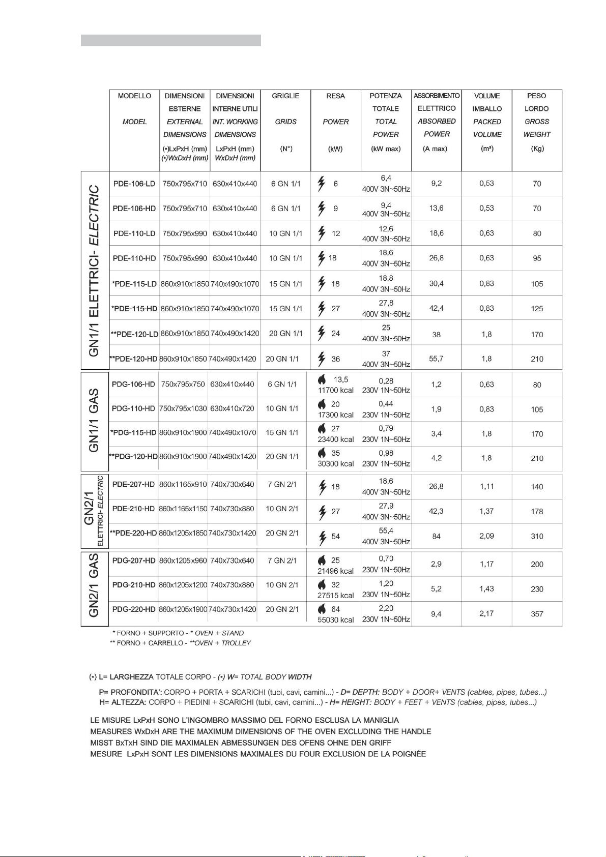
2. GENERAL TECHNICAL FEATURES
GASTRO PROFESSIONAL OVENS

21
PASTRY PROFESSIONAL OVENS

22
B
AC
1
2
3. WARNINGS FOR THE INSTALLER
Read carefully all the instructions in this manual, because they give important suggestions about the right installation, use and
maintenance of the appliance.
3.1. CONTROLS AT RECEPTION
The appliance are shipped in appropriate protective packing. On arrival, check that the appliance has not incurred in transport
damage and that it is complete according to the order. In the event of visible damage immediately note the damage on the transport
documents with the following wording: “RECEIVED WITH RESERVE FOR EVIDENT DAMAGE OF PACKING”.
ALL THE OPERATIONS INDICATED BELOW MUST BE PERFORMED IN RESPECT OF THE EXISTING SAFETY REGULATIONS,
BOTH FOR THE EQUIPMENT IN USE AND FOR THE OPERATING PROCEDURES.
3.2. HANDLING
BEFORE BEGINNING HANDLING OPERATIONS ENSURE THAT THE LIFTING CAPACITY IS ENOUGH FOR THE APPLIANCE IN
QUESTION. HANDLING with FORK LIFT or SIMILAR (A); Insert the forks into the side or back of the wooden pallet supplied with the
appliance, begin lifting checking that the appliance is in stable equilibrium. Attention: when insert the lifting device, pay attention to the
power supply cable and the position of the feet. DURING HANDLING DO NOT TIP OR TURN OVER.
the respect of the recommendations printed on the outside of the packing (D, E) is a guarantee of a sound physical and operating
condition of the appliance, all to the advantage of the end-user. therefore the following is recommended: handle with care, keep dry,
stacking of other objects on the appliance must be absolutely avoided, stacking of oven is permitted, taking care of the maximal
quantity reported on the packaging (D)
3.3. PLACING
Lift the appliance to separate it from the pallet (A). Remove the packing (B) and the protective film avoid using abrasive brushes or
other damaging materials for the appliance’s surfaces (C). Check that the appliance is perfectly levelled (C).
Regulate the adjustable feet if it is necessary. If you have a composition oven + neutral element, place the oven’s legs in the proper
place created in the top of the neutral element.Place the appliance away from heat sources and in a ventilated room. Never obstruct
any air inlet on the oven in order to not compromise its performance and safety when the equipment is operating .Place the
appliance in a site easy to join, so every type of maintenance, control and repair may be done easily.
D:GENERAL INDICATIONS ON THE PROTECTIVE PACKING
Maximal quantity of stackable units
E: INDICATIONS ON THE PROTECTIVE PACKING OF THE GAS OVEN
THIS APPLIANCE MUST BE CONNECTED FOLLOWING THE NORMATIVE LAWS
IN FORCE. THIS ITEM MUST BE USED IN A VENTILATED PLACE ONLY.
BEFORE THE INSTALLATION AND THE USE OF THE APPLIANCE.
INSTRUCTIONS MUST BE READ DOWN CAREFULLY. THIS PACKAGING HAS TO BE
PROPERLY RECYCLED ACCORDING TO THE EXISTING LOCAL REGULATIONS.
GB
GAS PREDISPOSED
II2H3+
G20
20 mbar
G30
28-30 mbar
CAT
G31
37 mbar
- It is strictly recommended to have a free space of 50 cm from the back side of the oven to the wall and from one of the two sides to
the wall in order to ensure a correct and easy connection to the equipotential system and to the electriocal and water system.
- it is recommended to have 4-6 cm of distance from the other appliances to guarantee a proper air circulation and avoid the near
surfaces to became overheated.
3.4. CONNECTIONS
3.4.1. AUTOMATIC WASHING SYSTEM (KLAC: OPTIONAL)
B2
A2
C
D
Washing box (fig. 1)
Back side of the oven (see different
models in fig. 2)
Connections:
A2 + A1
B2+B1
D+D1
C in detergent tank
Fig. 1

23
D1= ALLACCIAMENTO ACQUA
WATER SYSTEM CONNECTION
SCATOLA LAVAGGIO AUTOMATICO
AUTOMATIC
WASHING SYSTEM BOX
D= INTERCETTATORE
COCK
C
TANICA DETERSIVO
DETERGENT TANK
3.4.2. ELECTRICAL CONNECTION
For the direct connection to the electric system it’s necessary a device to ensure the disconnection fron the electric system, with a
contacts opening able to disconnect completely the electric system in the conditions of category of over voltage III, in accordance
with installation regulations.
The connection must be done according to the current local regulations. Verify that:
Voltage and frequency correspond to those stated on the data plate of the appliance.
The electrical plant supports the consumption of electricity of the appliance.
The electrical plant has a grounding to the current local regulations.
The appliance must be placed in such a way that the interlocked switched socket-outlets to the network can be easily reached.
Example of type of electric cable:
Cable type
Ø (mm²)
kW electric
FG7R/FG70R
5x10
36
FG7R/FG70R
5x6
27
FG7R/FG70R
5x6
24
FG7R/FG70R
5x4
18
FG7R/FG70R
5x4
12
FG7R/FG70R
5x2,5
6
FG7R/FG70R
5x2,5
9
FG7R/FG70R
3x2,5
3,2
When the appliance is operating, the power supply voltage must not diverge from the value of the nominal voltage, indicated on
the data plate, by more than ± 10 %.
Gas ovens are equipped with cable and Schuko plug (single phase 230 V).
Insert the plug in the socket only if you are sure that the socket is right for the plug. Three phases ovens are not supplied with
electrical cable, therefore it is necessary to connect to the oven internal terminal board a cable of proportionate section.
Cable replacement: after opening the lower cover, placed in back side of the oven (unscrew the fixing screw), connect the
conductives in accordance with the selected wiring diagram. Fix the cable to the suitable cable gland and close the back cover.
The connection or replacement of the cable has to be done by authorized personnel.
If the cable is damaged it has to be sustituted by authorized personnel.
3.4.2.1. EQUIPOTENTIAL SYMBOL
EQUIPOTENTIAL CONNECTION: it’s necessary when different appliances have to be connected (electrical or neutral) in an equipotential
system.
B1
A1
Fig. 2
TAP

24
12
34
3.4.3. WATER CONNECTION
Between the water system and the appliance you have to put a tap.
The appliance is equipped with a 3/4’’ male thread and of a mechanic filter. The appliance is equipped with a connection water set:
you have to use only this for oven’s water connection! You have to screw the female thread of the tube to the mechanic filter of ¾’’.
Before installing the alimentation tube is recommended to let flow running water to clean impurities and dust.
Characteristics of water:
- it is recommended a pressure less than 200 kPa for the enter of water.
- for greater pressures, install a pressure regulator calibrated at 200 kPa.
- water max temperature= 30° C
- maximum hardness: 5°F (to avoid calcium deposits, which are harmful for the equipment).
- it is recommended the installation of a water softener to avoid the formation of mineral depots.
OPERATION TO PERFORM DURING THE INSTALLATION PHASE TO THE WATER NETWORK: After performing the
installation to the water network, it is compulsory to run a washing set up, as described in paragraph WASHING SYSTEM.
3.4.4. GAS CONNECTION
The section of the enter gas tube depends on the gas type and on the consumption of the installed oven. The connection must be
done according to the current local regulations. The gas oven is equipped with a ½’’ male thread positioned in the back side of the
oven (see the drawing below).
The connection has to be done with fitting adapters and gaskets appropriate for the used gas type (see technical data).
A fast acting shutoff valve must be installed on the gas inlet line to the oven. The valve must be type test approved according to the
current regulations. The connections of the gas main can be permanent or detachable; if flexible metal tube is used, this should be
made of stainless and corrosion resistant material (do not use rubber hose!). Every type of chosen sealing material used for
connections have to be tested and approved for this purpose. All connections between the mains and the appliance must be tested
for leakage. The recommended method is to use a proprietary leak detection spray or a non-corrosive foamy liquid of any general
description can simply be brushed onto the fittings: the important thing is that NO BUBBLES SHOULD APPEAR. WARNING: NEVER
ANY CIRCUMSTANCES TEST FOR GAS LEAKS WITH A NAKED FLAME.
3.4.5. DRAINING WATER AND STEAM EMISSION
Water
The water is drained through a pipe made of a heat resistance material. The temperature of the draining water is about 90°C. It must
be positioned in the back side of the oven and connect to a siphoned drain through a rigid or flexible pipe. The diameter of the pipe
will be 32 mm and length 1,00 mt without elbows or narrow passagings and in order to an easy drainage it is recommended
installing 20 cm under the draining connection.
Vents
Vents are positioned on the top of the oven: don’t block, shut or duct into other pipes. Kept a distance between the vents and
materials or furniture which could be damaged. Gas oven may be positioned under a suction hood or under a ducted ceiling suitable
for gas.
3.5. GAS OVENS: SOSTITUTION OF NOZZLES.
TABLE FOR NOZZLE SUBSTITUTION
THERMIC NOMINAL POWER
NOZZLES
marking
kW 13,5
G30 28..30 mbar G31 30…37 mbar
90
G30 50 mbar G31 50 mbar
80
G20 20 mbar
140
G25 25 mbar
150
G25 20 mbar
155
kW 20
G30 28..30 mbar G31 30…37 mbar
110
G30 50 mbar G31 50 mbar
95
G20 20 mbar
175
G25 25 mbar
185
G25 20 mbar
195
You have to close the gas tap before make any operation.
A- Unscrew the 4 screws which fix the back cover panel of the burners.
B- Remove the lower back cover panel of the burners
COVER OF THE
BURNERS
BURNERS

25
1
2
3
4
LEFT BURNER RIGHT BURNER
Burners
C- Unscrew the screws 1, 2 of the left burner and 3,4 of the right burner.
7
D- Remove the left burner and after the right one.
E- After removing the burners, unscrews the 2 nozzles of the left burner and the 2 nozzles of the right burner.
F- eliminate the nozzles + washer
G- mount the new nozzles in the place of the old ones .
H- mount again the burners and fix them with their own screws.
I- mount the burner lower panel and fix it with its own screws.
L- open the gas tap.

26
4. INDICATIONS FOR THE FINAL USER
4.1. POWER SUPPLY
When the card is powered up goes to STAND-BY status, if there wasn’t a cooking cycle carrying out, in the moment of the switching
off. If a cooking cycle was carrying out it goes to TEMPORARY STOP.
4.2. POWER OFF
The card is powered off: led, keys or the displays are off.
4.3. STAND-BY
In this status the card is powered up. All the displays and led aren’t lightened. Only the (1) ON-OFF key is lightened.
By pressing the ON-OFF key the card goes to READY mode.
4.3.1. PARAMETERS MANAGEMENT
In stand by mode you can enter in Menu 'Parameters, press MENU (11) and WASHING (14) at the same time for 3 sec. The display
shows the written ‘’SERVICE PARAM’’. You have to push ENTER (12). The display shows the written PASSWORD. Press the key
ENTER (12).
The first voice of menu service is ‘’PARAM’’ and is useful for the parameters management. The PARAMETERS are protected with a
password; when you try to enter in parameters menu you have to digit the password, with the rotation of the encoder (13) and confirm
by pressing the key ENTER (12): for the final use is ‘’0’’ (zero).
IND
DESCRIPTION
MIN
MAX
DEF
UM
42
Timeout light
0
30 min
60
s
46
Languages
0
5
0
---
48
Aspiration time with the key U-
10
60 sec
10
s
49
Injection time with the key U+
10
30
10
s
79
Pre-heating temperature offset
0
25
0
°C
Within parameters menu is showed the parameter index and its value. You may run the various parameters with the encoder.
By pressing the key (12) ENTER you select the parameter and the led PHASES begins to blink: it means that you can modify it.
You can change the value with the ENCODER (12). BY pressing ENTER you confirm the value, by pressing the key ERASE (10) you
go out from the changing of the parameter without confirm the modify. By pressing the key ERASE (10) you go back menu service.
4.4. READY
In this mode the card is ready to set up and start a cooking cycle. ON-OFF led switches off.
If you pass in this mode the temperature’s display shows for 5 sec the choose set (is lightened the dot at the right of the last digit) and
after it shows the measured chamber’s temperature (the dot is not lightened) . The visualization of the choose set (chamber or delta-
T) is identified by the lightening of the dot at the right side of the last digit. The displays of programs and temperatures and the led of
humidity and phases, carry the set up of the last manual cooking cycle’s memorized. The lightened phases’ led number show the
number of the phases of the selected program and the blinking phase’s led shows which phase is at present visualized.
If there are alarms they are shown in program’s display and the buzzer sounds. At the first pressure of a key the buzzer stop to
sound. If it’s possible the alarm’s manual restore, it has done by a long pressure of the key (10) . If there are no alarms and with a set
up and confirmed the short pressure of the START/STOP (2) key starts a cooking cycle and the card goes to START mode. The card
goes to STAND-BY mode with a long pressure of the (1) ON/OFF key.
4.4.1. SET UP A COOKING CYCLE
Set up a cooking cycle is a binding and auto-corrective actions’ sequence from top to lower part. It means that the cooking mode
(Time or Core Probe) and the type of temperature’s setting (chamber or delta t) will be not in contradiction and will be always
consistent: for example isn’t possible setting up a cooking time mode with a delta-t.
Cooking modes accepted:
- Time and chamber’s set point
- Core probe and chamber’s set point
- Core probe and delta T
The cooking mode has the setting up priority. It means that if it’s set up the TIME mode and CHAMBER’S SET POINT is not possible
setting up DELTA T mode, infact it starts the alarm’s sound. It’s necessary to set up first of all the CORE PROBE mode and after
DELTA T mode. The setting up is auto-corrective, it not allows incongruous set up. For example if core probe mode and delta t mode
are set up and after it’s set up TIME mode also will be automatically set up CHAMBER SETPOINT mode.
4.4.1.1. TIME COOKING MODE
TIME COOKING mode needs the setting up of the cooking time and after of the chamber temperature.
To set up cooking time press the (4) TIME key (its led begins to blink). Time is showed in hh.mm. With (13) ENCODER it’s possible to
select a time between 0h.01min and 9h.59min, with 1 min. step length. It is also possible to set an infinite cooking time, displayed
as INF (if INF is selected, the time variable has an unlimited duration), and a pre-heating mode, displayed as PRE (see 4.4.1.7). The
mode for selection is rotation, that is, after 9h. 59min, INF, PRE is shown, and then 0h.01min.
The value is set up by pressing the
key (12) ENTER. If you don’t press keys or rotate the encoder, after a fixed time (default 10sec) the value goes back to its previous
setting and it not blinks. The same happens by pressing the key (10) CANC or (4) TIME. To set up the chamber’s temperature press
the key (6) CHAMBER TEMP. . Its led begins to blink. Temperature is showed in the unity of measure selected by a parameter. With
ENCODER is possible to select a temperature between a min and a max values set up by a parameter. Value is confirmed by
pressing the key (12) ENTER. After a fixed timeout without pressing keys and without rotating the encoder or by pressing the key (10)
CANC or (6) CHAMBER TEMP. the value goes back to its previous setting and it not blinks.
4.4.1.2. CORE PROBE COOKING
Core probe cooking has two different modes: CHAMBER SET POINT and DELTA T. CHAMBER SET POINT cooking needs first of
all the setting up core probe’s temperature and after chamber’s temperature. The set up of the core probe’s temperature is common
to both modes and is done by pressing the key (5) CORE PROBE. Its led blinks. The display shows the set of the temperature of the
core probe in the unity of measure selected by a parameter. With ENCODER is possible to select a temperature and set up the value
by pressing the key (12) ENTER. In the same way you can set up chamber’s temperature. You have to pay attention that chamber’s
temperature has to be higher than core probe ones defined by a parameter fixed by the constructor. DELTA T cooking needs first of
all to set up core probe’s temperature and after the difference between chamber’s temperature and core probe’s temperature.
the difference between chamber’s temperature and core probe’s temperature is set up by pressing the key (7) DELTA T. its led blinks.
The display shows the set of the difference. With ENCODER is possible to select a temperature and set up the value by pressing the
key (12) ENTER.
4.4.1.3. SET UP HUMIDITY
Humidity set point is showed by 10 lightened led .They represent a humidity scale of 11x2 values from steam cooking (5 bleu led
lightened) to dry cooking (5 red led lightened). To set up the chamber’s humidity you have to press the key (8) HUMIDITY. It begins
to blink, so is possible to select the humidity with the ENCODER (13) and memorize with the key (12) ENTER.
4.4.1.4. SET UP FAN SPEED
With the key (3) FAN SPEED is possible to select the fan speed, if it is enabled by a parameter fixed by the constructor. You can go
to high and low speed by pressing the key (3); the low speed is showed by its lightened led. When is selected high speed the led of
the (3) key is not lightened. It’s possible to set up different fan speeds during the different cooking phases.

27
4.4.1.5. COOKING PHASES
Every cooking cycle, manual or from memorized recipes, may be composed of max 4 phases. The number of lightened led phases
shows the specific phase actually visualized. The selection phase may be changed by pressing the key (9) PHASES.
You can erase the selection phase by a long pressing of the key (10) CANC. The following phases move towards left of one position
(the yellow lightened led of the phases). It isn’t possible to erase all the phases because a cooking program has to be composed of
minimum a phase. You can create a new phase equal as the selected one; the new phase will be add after the selected one. The
following phases of the selected one move to the right side of one position (the yellow lightened led of the phases). It isn’t possible to
create a phase after the 4. If there are four phases and you create a phase after the 4th the actual fourth will be erased and
substituted by the new.
4.4.1.6. DELAYED COOKING CYCLE
To set up a delayed cooking cycle, you have to select with the ENCODER (13) the temperature under the minimum value 30°. On
visualizer B will appear ‘’PAU’’ ,it means that in this cooking phase the oven will be in pause for a fixed time that you’ll see on
visualizer A. At the end of that phase, if there’ll be a following one, the oven will go in this following phase.
4.4.1.7. PREHEATING
If you want to preheating the oven before start cooking, you have to set up 2 cooking phases: the preheating and the cooking (you
can obviously add new phases).The operations’sequence :
set phase 1, with PRE time and preset heating temperature.
2. You have to create the 2 phase
3. You have to modify the 2 phase with appropriates cooking time and temperatureb (the 2 phase can be also core probe Δt
type)
After these operations the oven is ready to start.
By pressing the key (2) START/STOP, the oven starts without charge of cooking foodstuffs and goes to the set up temperature in the
1 phase: when the set up temperature of preheating is reached, the board sounds 2 bip.
From this moment onward you can put the meals to cook into the oven. When the oven door is re-closed, the transition to the next
phase will occur automatically (2 bips are emitted). If the door is opened and closed before the oven reaches the final pre-heating
temperature (i.e. before the 2 bips are emitted), the transition to the next phase will occur anyway.
Afterward you have to pass manually to the 2 phase by a long pressing of the key (9) (there is a sound of 2 bip).
4.4.1.8. COOLING
When the oven is in STOP status (so with the cycle not started), a fast cooling can be carried out with opened door. In fact, the
message COOL is shown on the flag-shaped display and the ENTER (12) and CANC (10) keys flash simultaneously when the door is
opened. If ENTER is pressed, the cooling option is confirmed, but with CANC, the oven normal operation is resumed. If the cell
temperature is below 60°c, cooling cannot start.Once the COOL option is confirmed, the cooling is started by just pressing the
START/STOP (2) key. Cooling finishes when a temperature of 60°c is reached or when the door is re-closed. In any case, cooling can
be interrupted just by pressing the START/STOP (2) key.
4.4.2. COOKING PROGRAMS
The oven can memorized max 200 programs (comprehended those pre- memorized by the constructor) with names of maximum 10
letters. The programs are organized in 2 levels: the first level consists of 7 categories of program: MANUAL-POULTRY-MEAT-FISH-
VEGETABLES-CAKES-BREAD-PIZZA-MISCELLANEOUS. The second level defines the particular program (for example:
CHICKEN, DUCK, ROAST …). Each category (except MANUAL and WASHING) can be made of a great number of programs (the
only limit is 200 max number of total programs). The oven has a set of pre-memorized programs memorize by the constructor and
they can’t be modified. They are available translated in 4 languages but there is no automatic translation for new names memorized
by the final user. It’s not allowed move or clone programs from a category to another. You enter in PROGRAMS mode by short
pressure the (11) MENU/MEMO key. The blinking MENU/MEMO key shows that it is in selection of programs and it’s possible to see
the programs of the current category. On the running display is visualized the program (second level). With (13) ENCODER run the
programs and with (12) ENTER key select the program. You can go to a superior level (category of program) by short pressure of
(10) CANC key, MANUAL mode is particular because it hasn’t a list of programs of second level. So when is selected MANUAL
mode, by pressing the key (11) MENU/MEMO passes immediately to program’s category selection. MENU/MEMO lightened shows
that it is in selection of category of program. On display runs the name of the carrying out category of program (first level). By rotating
the ENCODER (13) you can run the categories, when appears the right one by pressing (12) ENTER you confirm the category. With
a single pressure on the key (10) CANC you go out to programs mode. If you modify the selected program the modifies are
memorized at the moment but not saved for the following ones. By a long pressing of the key (12) ENTER you save the modifies to
the program (except for the no-modifiable ones). With the key (9) PHASES you can run all the phases of the program and modify
them (see 4.4.1.5.) By pressing for 5 sec. the key (10) ERASE (in selection program mode) you erase the visualized program. It isn’t
possible to erase the constructor’s memorized and fixed programs. By pressing the key (2) START/STOP you start the selected
program. By pressing for 5 sec. the key (11) MENU / MEMO (with the program selected not from the list of programs) you can clone
the selected program. When is selected manual program every modify is immediately saved. The programs have a name and an
index (the dots that you can visualized on ‘’D’’ display) So the program CHICKEN [2] is represented writing CHICKEN on display ‘’D’’
and lightning two dots at the left of the display ‘’D’’. By cloning a program you see on ‘’D’’ display, the name of selected program and
the first available index. It’s possible to have max 6 clones of the same program; if there are already existing 6 clones you have an
number six with the opportunity to overwrite. For the programs with long names (more than six letters) you read the last six letters of
the name. The last digit is blinking, it means that it can be modified by routing the ENCODER (13). By pressing the key (12) ENTER,
the writing runs of a digit towards left adding a new symbol ‘’_’’ (underscore) blinking and modifiable at the end of the name. By
pressing the key (10) ERASE you can remove the last digit of the name, by running the name towards right and modifying its new
last letter. If you want to change all the name it is necessary press repeatedly the key (10) ERASE until remains one digit blinking. So
you can write the new name. Is not possible to choose the index of a program, it is automatically assigned. In that case you can read
the name of the constructor proposed program and the first index available. By pressing the key (10) ERASE if you are in menu
modify you’ll not save the program. If you search for save a new clone program after the reaching of 100 programs will appear
“FULL MEM”; it’s possible to over write one of the already present ones or erase one of the memorized.
4.5. START/STOP
In START/STOP mode the card starts the selected cooking cycle and begins the modifications. By a long pressure on the key (2)
START/STOP the card will be in READY mode. By pressing the key (2) or opening the door the card goes to TEMPORARY STOP.
It’s possible to modify the settings of the carrying out coking cycle; they’ll not save and are temporary memorized for the carrying out
cycle. At the end of the cycle they are erased. It’s not possible neither to change the way of cooking (TIME or CORE PROBE) nor
select a different program. By pressing the key (9) PHASES you stop the carrying out phase and you pass to the following one. The
buzzer sounds with a long bip. If there was carrying out the last phase the cycle will end. The carrying out phase is signed by the
PHASES’ blinking led. At the end of the cycle the card goes to READY mode and buzzer sounds with 4 bip.
4.6. TEMPORARY STOP
In TEMPORARY STOP MODE are hung the possibilities to choose values and the fan stopped. If the door is closed, by pressing the
key (2) START/STOP you start again the cooking cycle. If the interruption was due to an opening of the door (and not for the pressure
of the key (2) START/STOP) by closing the door the cooking cycle starts again. The card goes to the READY mode by a long
pressing of the key (2) START/STOP. It’s possible to make modifies to the set of the carrying out cooking ; they are not memorized
and are valid only for the moment of that cooking. At the end of the cycle they are erased. It is not possible to change the cooking

28
mode (TIME or CORE PROBE) and select a different program. The carrying out phase ends by pressing the key (9) PHASES and
you go to the following one. The buzzer sounds with a long bip. If was carrying out the last phase the cycle ends. The carrying out
phase is showed by the blinking led ‘’PHASES’’.
4.7. USB CONNECTIONS (OPTIONAL)
You can have the possibility to use the USB (Mass storage device) for the management of the recipes; in particular you can import
and export programs of cooking. You can enter in menu USB, at the end of the list of categories of program: press MENU (11) and
rotating the l’ENCODER (13) you can read: MANUAL --> POULTRY --> MEAT --> FISH --> VEGETABLE -->PASTRY --> BREAD--
>PIZZA-->VARIOUS-->USB . This menu appears only if a USB is connect; on the contrary it shows only the last category.
Press ENTER (12) to confirm the choice menu USB, you can find a list of two options: IMPORT, EXPORT (If you are in menu USB
and the USB is disconnect, you return to the last category of the program).
IMPORT OF RECIPES
You have to choose ‘IMPORT’ by pressing the key ENTER (12) (one of the two options): the oven’s software begins to import the
recipes contained in the formatted file REC_IN.csv. The formatting of the file is the following one:
>>
RECIPE a
>>
RECIPE b
...
>>
RECIPE n
>>EOF
All the recipes have the following format:
Recipe’s typology : category[1];name[10];number[1];overwriting[1]
Phase 1: way of cooking[1];humidity[2];set of the chamber[3];set of the time [3];set of the core probe[3];set of the delta t[3];set of the
fun [2]
Phase 2: way of cooking[1];humidity[2];set of the chamber[3];set of the time [3];set of the core probe[3];set of the delta t[3];set of the
fun [2]
Phase 3: way of cooking[1];humidity[2];set of the chamber[3];set of the time [3];set of the core probe[3];set of the delta t[3];set of the
fun [2]
Phase 4: way of cooking[1];humidity[2];set of the chamber[3];set of the time [3];set of the core probe[3];set of the delta t[3];set of the
fun [2]
The number between the square brackets at the side of each field indicates the number of alphabetic characters of which is
composed every name of the fields. The meanings of every field are the following :
Category: is the category to which the recipe belongs. The accepted values are:
0 manual; 1 poultry; 2 meat; 3 fish;4 vegetable; 5 pastry; 6 bread; 7 pizza; 8various
Name: is the name of the recipe showed on the display. Every writings have 10 alphabetic characters maximum. The accepted
alphabetic characters are : all the capital letters, the numbers, underscore, space, dash.
Number: number of identification of the programs with the same name (clone). The number is represented by dots on display. It can
vary from 0 to 6 dots.
Overwriting: you are importing a recipe with the name of a just existing one. There are only two values:
0= no overwriting. A new clone is created and identified with the first free number. Example: if are memorized CHICKEN, CHICKEN
[1], CHICKEN [3] and you are trying to import CHICKEN, it’ll be created a new program CHICKEN [2]
1= overwriting. If it is possible, you can overwrite a just existing program (it isn’t possible if it is a program fixed by the manufacturer).
Cooking ways: The way of cooking and its phases. The accepted values are:
0 : no phase (named with zero ‘’0’’: the following ones aren’t memorized)
1 : time cooking mode
2 : core probe cooking mode
3 : delta t cooking mode
Humidity: it represents the value of humidity of a specific phase. The values may be from 0 to 10: 0=cooking with no steam,
10=cooking with steam.
Chamber set, core probe set, delta t set: these are all the set points of the chamber, of the core probe and of the delta t cooking
and their own phases. The accepted values go from 0 to 275.
Time set: this is the cooking time of the interested phase, in a time cooking mode, it is expressed in minutes.
This time go from 0 (infinite cooking) to 599 (9h:59min).
Funs set: is the speed of funs rotation in the interested phase. The values are 0 (half speed) and 1 (high speed). If you use less than
4 phases it isn’t necessary to set up the values of the remaining ones with 0 (NO PHASE).
Example of a file REC_IN.csv (bold font); near you can read the meaning.
>> 001 New recipe (the progressive number is not important)
0; ;0;0 manual program (name, number and not important overwriting)
1;05;150;010;050;020;01 phase1 time 10 min 150 centigrade, humidity 5, funs with high speed
1;05;250;010;050;020;01 phase2 time10 min 250 centigrade, humidity 5, funs with high speed
>> 002 New recipe (the progressive number is not important)
1;CHICKEN ;0;1 Category Poultry, name CHICKEN, no clone, overwrite
1;05;220;015;050;020;01 phase 1 time 15min 220degree, humidity 5, funs with high speed
1;05;190;045;050;020;00 phase 2 time 45min 190degree, humidity 5, funs with normal speed
1;05;225;010;050;020;01 phase 3 time 15min 225degree, humidity 5, funs with high speed
>> 003 New recipe new recipe (the progressive number is not important)
1;CHICKEN ;1;0 Category Poultry, name CHICKEN, clone n1, no overwrite
1;05;220;015;050;020;01 phase1 time15min 220degree, humidity 5, funs with high speed
1;05;190;045;050;020;01 phase3 time15min 225degree, humidity 5, funs with high speed
>>EOF End of the file
Importation of recipes sometimes needs a lot of seconds (importation of a big quantity of recipes); during the waiting time on display appears
‘’WAIT’’. When the total number of the recipes is 100 (the maximum number made of manufacturer + user), it isn’t possible to create new
recipes and the file REC_IN.csv considers only the recipes’ overwriting.
EXPORTATION: If you choose EXPORT press the key ENTER (12) so begins the exportation of the recipes memorized in the oven. Recipes
are saved in a file csv file formatted named REC_OUT.csv. The format of the exportation file is like the importation ones, so it can be used to
create a file of importation. The recipes are exported in the order of category and in every category are disposed in alphabetical order (like the
list you can see, if you run the programs on display). At the beginning of every recipe you can see a progressive number (>>000, >>001,
>>nnn), useful to find the total number of recipes memorized in the oven. This number may be left in the importation file of the recipes: this
number is ignored and has no meaning. During an exportation appears the writing ‘’WAIT’’ on display.
4.8. WASHING (OPTIONAL)
Attention: you have to do this operation at the first installation Washing set up: by pressing the key (14) washing one time

29
and then a second time (long pressure), in display d appear ‘’set up’’; after you must press the key (2) start/stop to perform
for about 2 minutes the charge of the soap.
Warning: SET UP will start up only if the oven chamber temperature is below 60º.
With the oven in READY MODE (ON/OFF led switched off) press the WASHING (14) key; Choose the duration of washing between
‘’NORMAL, STRONG or EXTRASTRONG and RINSE with the ENCODER (13) and then by pressing ENTER (12) to confirm your
choice. Pressing the key START (2) washing cycle start. WARNING: the washing cycle will start only if the oven chamber
temperatuer is 60º. By a long pressing of the key (2) START/STOP is possible to end the washing cycle. If the oven is not in START
mode you may reset and go back by pressing the key WASHING (14) and then the key CANC (ERASE, 10).
If the washing set up or a washing cycle does not achieve good results, it will be necessary to run a rinsing cycle or wash
the oven manually. This operation is necessary to prevent detergent traces from entering the cooking chamber during the
following cooking cycles and from coming into contact with the food.
4.9. HACCP MANAGEMENT (OPTIONAL)
The HACCP log for cooking can be performed only in models with clock management hardware.
The oven can record significant temperatures and events during the cooking cycle. In particular, the following data are stored:
- Date (day, month and year)
- Time (hour and minutes)
- Temperature of the chamber probe in degrees
- Temperature of the core temperature probe in degrees
- Chamber relay status (PWM 0: de-activated / PWM 100: activated)
- Significant events (start, stop, pause, door opening, cooking resume by power-up)
- Alarms
The events saved are:
START: start and resume of cooking after a pause
STOP: end of cooking
PAUSE: a pause in cooking
DOOR: door opening during cooking
POWER-UP: resume of cooking after a power-fail
The error codes saved are (they are visible by just downloading the log from the service menu):
1 Chamber safety
2 Fan safety
3 Burner safety
6 Communication fail
7 High temperature at power card
All errors in the chamber and core temperature probe are represented by ERR at the temperature value place (they are visible also in
the log downloaded by the user).Data are saved during the cooking cycle execution (START or TEMPORARY STOP status) and at
the end of cooking, as soon as the door is not opened, and for a maximum period of 15 min.Sampling occurs in a period of 5 min. or
every time the core temperature undergoes a variation over 5 degrees.The memory for saving may contain approximately 200
samples (it is possible to collect about 160 hours of data by sampling every 5 minutes); when memory is full, records related to the
oldest day in the memory are removed.The memory is emptied every time data are downloaded into a USB pen drive.Data are
downloaded into the memory by connecting a USB pen drive to the keyboard and by selecting the HACCP option in the USB menu at
the bottom of the list of program categories. Data are downloaded into a file named Hggmmaa.csv, in which gg/mm/aa stands for day,
month and year of the oldest cycle in the memory; if there is an existing file with the same name, it is overwritten.The file comprises
a heading with general information and a body with the information saved in the memory.Below, an example of HACCP log file
formatting is shown including errors (data have been tabulated for a better understanding):LOG HACCP: Software
version:XXXXXXX - Download date: 00/00/00 - 00:00
Date; Time; T Chamber; T Core; PWM; Event;
18/04/2011; 16:18; 23; 0; 0; START;
18/04/2011; 16:18; 24; 0; 100; ;
18/04/2011; 16:19; 78; 0; 100; ;
18/04/2011; 16:19; 94; 0; 100; ;
18/04/2011; 16:19; 107; 0; 100; ;
18/04/2011; 16:19; 124; 0; 100; ;
18/04/2011; 16:19; 146; 0; 100; ;
18/04/2011; 16:20; 149; 0; 100; ;
18/04/2011; 16:20; 148; 0; 100; DOOR;
18/04/2011; 16:20; 147; 0; 0; ;
18/04/2011; 16:20; 138; 0; 0; ;
18/04/2011; 16:20; 137; 0; 0; START;
18/04/2011; 16:20; 142; 0; 100; ;
18/04/2011; 16:20; 154; 0; 0; ;
18/04/2011; 16:20; 149; 0; 100; ;
18/04/2011; 16:20; 153; 0; 0; ;
18/04/2011; 16:20; 155; 0; 0; STOP;
18/04/2011; 16:20; 157; 0; 0; ;
18/04/2011; 16:21; 147; 0; 0; ;
In case of power fail, data and time are kept in memory for approximately 150 hours.
4.9.1. “TIME" CLOCK SETTING (ONLY IF HACCP IS PROVIDED)
This menu is found only if the clock management hardware is detected. It is a user’s menu that can be accessed without password by
pressing the ENTER key. Current date and time are shown on the flag-shaped display and then the menu for clock editing appears. If
no editing is made, it is possible to exit from the menu with the date and time unaltered by pressing the ESC key.
By means of the encoder, the displayed value is changed and confirmed, and the successive value with end-around shift can be
changed with ENTER. The displayed list of values is the following:
DAY xxday setting (01-31)
MON xxmonth setting (01-12)
YEA xxyear setting (11-50)
HOU xx hour setting (00-23)
MIN xxminute setting (00-59)
The new datum is confirmed and the new data is written by pressing the ESC key; seconds are set to 0.
4.10. SWITCHING OFF
To finish the cooking in every moment press the key (2) PAUSE/STOP. To switch off the oven press the key (1) ON/OFF.
30
1
2
3
4
5
6
7
8
9
10
11
12
13
14
15
16
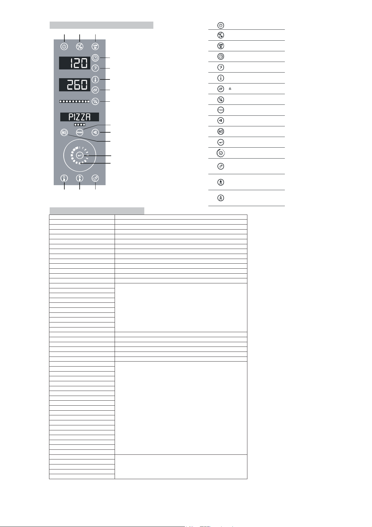
ON/OFF
START -STOP-TEMPORARY STOP
LOW SPEEDFANS
COOKINGTIME
CORE PROBE
COOKING CHAMBER TEMPERATURE
t° COOKING SYSTEM
HUMIDITY
COOKING PHASE
DELETE-BACK
MENU-SAVE RECIPE
CONFIRM
SELECTION
MANUAL INCREASE OF HUMIDITY
MANUAL DECREASE OF HUMIDITY
WASHING (OPTIONAL)
DELAYEDCOOKING
5. CONTROL PANEL AND LEGEND
-+
6. VISUALIZATION ON DISPLAY
DISPLAY
DESCRIPTION
PARAM
Menu service to enter in parameters
CLOCK
Menu service to set the clock
SERV_1
Menu service to test the card
SERV_2
Menu service to erase the user's program
VERS
Menu service to visualize firmware version
THERM
Thermic error safety-Error of the thermic protector
FAN
Fan error
BURNER
Burner error
CHAMPR
Chamber's probe error
COREPR
Core probe's error
SERCOM
Serial communication error
TPCARD
Power card temperature error
GENER
General error
MANUAL
Category of a program
POULTRY
MEAT
FISH
VEGETABLE
PASTRY
BREAD
PIZZA
VARIOUS
WASHING
FULL MEMO
Full memory when you try to safe a program
OVERWR
Request of overwriting for a program
USB
USB Menù
IMPORT
Recipe's importationda USB
EXPORT
Recipe's exportation da USB
HACCP
Exportation file log HACCP
DUCK
Recipe's name memorized by the producer
CHICKEN
TURKEY
PORK
BEEF
VEAL
BASS
TURBOT
TROUT
PRAWNS
CARROTS
POTATOES
PEAS
CHICORY
BRIOCHE
PANETTONE
BAGUETTE
MARGHERITA
RISING
NORMAL
Washing programs (OPTIONAL)
STRONG
EXTRSTRONG
RINSE
SETUP
1
4
5
6
7
8
10
11
9
12
13
23
16 15 14

31
7. DIAGNOSE OF ALARMS (ERRORS) AND RESTORE OF THEM
All the alarms are showed on display.
7.1. CHAMBER’S PROBE
With the card in READY, START or TEMPORARY STOP mode , if you see on display ‘’ CHAMPR’’ and you hear the sound of the
buzzer, there is a problem with the chamber’s probe. If a cooking is carrying out , it will stop immediately, and the card goes to
READY mode. The buzzer stops by pressing every key. There is an auto-restoring of the chamber’s probe.
7.2. CORE PROBE
If the core probe has a problem, with the card in READY, START or TEMPORARY STOP mode, and the current phase or one of the
following ones, includes a CORE PROBE COOKING or a DELTA T COOKING, the cooking stops and the card goes to
TEMPORARY STOP mode. On display you see ‘’COREPR’’ and the buzzer sounds. The card doesn’t go to ‘’ALARM’’ or ‘’ERROR’’ if
it is in READY, FALL IN VOLTAGE or STAND-BY. By pressing every key you stop the buzzer. The restoring is automatic when the
core probe is in function again (auto restoring).
7.3. SERIAL COMMUNICATION
If there is no communication between power card and keyboard for more than 10 sec., the keyboard goes to ‘’ALARM’’ or ‘’ERROR’’:
the buzzer sounds and you visualize ‘’COMSER’’. The card doesn’t go to ‘’ALARM’’ or ‘’ERROR’’ if it is in FALL IN VOLTAGE or
STAND-BY. The carrying out cooking is stopped and the card goes to READY mode. By pressing every key you stop the buzzer. The
restoring is automatic when there is communication again (auto restoring).
7.4. POWER CARD TEMPERATURE
If the temperature of the power card exceeds the value fixed by the producer, the power card goes to alarm mode: you see on display
‘’TPCARD’’ and buzzer starts to sound. The card doesn’t go to ‘’ALARM’’ or ‘’ERROR’’ if it is in FALL IN VOLTAGE or STAND-BY.
The carrying out cooking is stopped and the card goes to READY mode. By pressing every key you stop the buzzer. The restoring is
automatic when the temperature returns under the fixed safety limit (auto restoring).
7.5. OPEN DOOR
In START mode, if there is an open door the card goes to TEMPORARY STOP and START/STOP led begins to blink. Every carrying
out cooking is stopped until the closing of the door.
7.6. SAFETY ENTRANCES
The card has 3 safety entrances: chamber’s safety, burner’s safety, fan’s safety.
If the card in READY, START or TEMPORARY STOP mode, you can see on display the message (of its own error) and the buzzer
starts to sound.
On display you can see:
‘’THERM’’: Thermic error safety
‘’FAN’’: Fan error
‘’BURNER’’: Burner error
The card doesn’t go to ‘’ALARM’’ or ‘’ERROR’’ if it is in READY, START or TEMPORARY STOP mode.
Every carrying out cooking is stopped and the card goes to READY mode. To restore you have to press the key (10) ERASE.
7.7. FALL IN VOLTAGE
When you have a fall in voltage and the card is in START or TEMPORARY STOP, at the following power on the card goes to
TEMPORARY STOP and the eventual interrupted cooking re-starts. The temporary program is memorized after every 10 minutes and
kin changing of phase. If the card wasn’t in START or TEMPORARY STOP, it goes to STAND BY and supports the memorized
manual program. There are no alarms or errors or buzzer’s sounds
8. ORDINARY MAINTENANCE
This section is dedicated to the end user and is important for the appliance to work correctly in the long term. A few simple
operations conscientiously carried out at set periods can avoid the need of servicing by specialised personnel.
The operations to be made do not require any particular technical knowledge and can be summarised in simple controls of the
appliance components.
BEFORE BEGINNING ANY TYPE OF MAINTENANCE OR CLEANING WORK ON THE APPLIANCE DISCONNECT THE MAINS
POWER SUPPLY (gas, electric, water).
OVEN’S CLEANING
At the end of the working day, clean the oven inside and out:
1- use only warm water and soap or a neutral detergent
2- rinse with plenty of water dry thoroughly
3- dry thoroughly
All food residuals and grease must be removed from the oven each time it is used for cooking; follow the 1-2-3 indications below.
Do not use abrasive materials and other products which could be damaging for the inox surfaces.
Use only alkali based products suitable for the purpose.
Do not use high pressure water jets to clean the oven.
If the oven does not work properly, switch the oven off, disconnect the electricity and water supply and notify the technical assistance
service.
For an extended period of non use we recommend to:
1- switch off the appliance by long pressing the (1) ON/OFF key
2- disconnect from all powers supply electric, gas and water
3- leave the door ajar to avoid bad odors from forming
The appliance should be checked at least once a year by qualified and authorised personnel.
9. UNPACKING AND DISPOSAL OF IT
Keep the packing out of the reach of children, as it could be a danger hazard.
Discharge the packing products to the specialised collection or recycling points in respect of the existing regulations.
10. DISPOSAL OF UNIT
Before scrapping the appliance, keep it inoperative by removing the power cable, eliminating all parts of the appliance that could
constitute an hazard and invalidate locks, hinges and any other closing devices to avoid that children playing could be trapped inside
or injured.
COMPLY WITH LOCAL REGULATIONS IN FORCE CONCERNING THE FINAL DISPOSAL OF THIS TYPE OF EQUIPMENT.
This manual suits for next models
27
Table of contents
Other Primax Oven manuals

Popular Oven manuals by other brands


Elba
Elba C 96 DF Instruction for the use - installation advice

Bakers Pride
Bakers Pride BCO-G Installation and operating instructions

VOX electronics
VOX electronics HWRC7315B user manual

Smeg
Smeg CE6GPXU Instructions for installation and use

GE
GE JCK5000 owner's manual

Frigidaire
Frigidaire FEB27T6DCA parts catalog