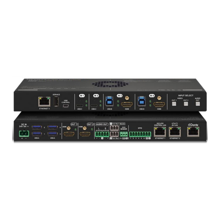
Primova GX-2 User manual

Reference Manual
Version 0.0
2021-01-20

TABLE OF CONTENTS
2
Table of Contents
Table of Contents ......................................................................................................................................... 2
Getting Ready ............................................................................................................................................... 3
Connecting the Equipment ....................................................................................................................... 3
Operating the device ................................................................................................................................ 4
Setting up the system for switching between two guitars....................................................................... 5
Menus (SYSTEM/PATCH) .......................................................................................................................... 6
How to edit menu parameters ................................................................................................................. 6
How to exit the settings menu ................................................................................................................. 6
Basic SYSTEM Menu settings .................................................................................................................... 7
Setting up Assigns ......................................................................................................................................... 9
GK Control Assigns .................................................................................................................................... 9
CTRL1 and CTRL 2 Assigns ...................................................................................................................... 11
ASSIGN1 – ASSIGN8 ................................................................................................................................ 13
MIDI ............................................................................................................................................................ 15
Patch settings menu ................................................................................................................................... 17
GENERAL PATCH SETTINGS .................................................................................................................... 17
SUSTAINER EFFECT ................................................................................................................................. 18
SLOW GEAR EFFECT ................................................................................................................................ 19
MODULATION EFFFECT (1 and 2) ........................................................................................................... 20
MODULATION Touch Control ............................................................................................................. 22
ARPEGGIATOR EFFFECT (1 and 2) ........................................................................................................... 23
ARPEGGIATOR Touch Control ............................................................................................................. 25
GK DIVIDER EFFFECT ............................................................................................................................... 26
Theory of operation.................................................................................................................................... 27
Technical data ............................................................................................................................................ 28

GETTING READY
3
Getting Ready
Connecting the Equipment
Never connect or disconnect while power is ON
GUITAR INPUTS
IN1
13
-
Pin
Di
vided pickup
GUITAR OR
BASS *
IN2
13
-
Pin
Divided pickup
GUITAR OR
BASS *
IN3
Normal
Electric Guitar or Bass
* NEVER CONNECT TO 13-PIN SYNTH INPUT
MAY CAUSE PERMANENT DAMAGE!
SYNTH OUTPUTS
GKA
13
-
Pin GUITAR SYNTH
GKB
13
-
Pin GUITAR SYNTH
EXTERNAL
CONTROLS
-
OPTIONAL
CTRL1
ROLAND EV
-
5 Expression Pedal or
FS-5U/FS-6/FS-7 Dual Footswitch
CTRL2
ROLAND EV
-
5 Expression Pedal or
FS-5U/FS-6/FS-7Dual Footswitch
MODE/POLARITY Switch
MIDI
-
OPTIONAL
IN
MIDI CLOCK
Device
or
MIDI
Controller
OUT1
Guit
ar Synth (1) MIDI IN
OUT2
Guitar Synth (2) MIDI IN
USB
-
OPTIONAL
USB
Connect to a PC using a Mini USB
2.0 cable
NOTE: Only connect to PC while
programming the device using a
dedicated software. A PC USB
connection may induce ground
loops/noise.
POWE
R
9VDC
Connect to a noise free 9V DC
Power supply >=500mA, 2.1mm,
Center pin negative.
Recommended:
Boss PSA or NUX ACD-006A
NOTE: Cheap “bulk” power supplies
may induce noise or even damage
your equipment.
MIDI SYNC
MIDI (SysEx)
MIDI (SysEx)
SY-1000, GR-55, VG/VB-99 or GP-10*
*MIDX
-
20 requir
ed for GKSET control via MIDI
1/4” STD 2 x GK(13-pin)

Operating the device
GK MODE
FOOT SWITCHES GKA STATE PATCH NUMBER PATCH NAME GKB STATE
D C
BPM DEPTH EFFECT STATE
PATCH MODE
A B
PATCH NUMBER BPM DEPTH EFFECT STATE
MODE CHANGE
B+C
Switch between
GK MODE
and
PATCH MODE
GK MODE
A
GKA
SYNTH
OUTPUT
ON/OFF
B
GKB
SYNTH
OUTPUT
ON/OFF
A+B
TOGGLE GKA AND GKB ON/OFF
PATCH MODE
A
PATCH DOWN (Previous Patch)
B
PATCH UP (Next Patch)
COMMON COMMANDS
C
PATCH
EFFECTS
ON/OFF
D
TAP TEMP
If you press TAP TEMPO only once, all effects using BPM will START a new phrase or
sequence. To set a new BPM you will have to TAP at least three times before the BPM
will change. If you TAP more than three times the aggregated average of all TAPS will be
used.
TAP TEMPO does not work if connected to a MIDI CLOCK source.
HOLD C
SETUP MODE
HOLD D
INPUT SELECT
A+S1/S2
S1/S2
buttons
to GKA
only
,
as long as
A is pressed.
B+S1/S2
S1/S2
buttons
to
GKB only
,
as long
as B is pressed
.
C+S1/S2
S1/S2
buttons
change
patch in GX
-
2
, as long as C is pressed.
The LED indicators show selected guitar, enabled synth outputs and BPM rate.

GETTING READY
5
Setting up the system for switching between two guitars
Each guitar is a unique individual with certain characteristics. This is why most guitar synths using a
divided pickup need to be calibrated using the synth GK SETTINGS. In some cases with two similar
guitars the main characteristics are the same but still the volume will differ if the distances between
each string and the divided pickup are different.
Simplified configuration
In the simplified configuration you do NOT connect MIDI cables between GX-2 and the synths and both
guitars will share the same synth GK SETTING.
Use the following steps to compensate for variation in string volumes between two guitars:
1. Keep all string volumes at 100 (DEFAULT) for the divided pickup connected to IN1.
2. Program the GK SETTINGS in your synth(s) so it works perfectly with this guitar.
3. Adjust the GX-2 string volumes for the divided pickup connected to IN2 so they correspond to
the same levels as with the guitar connected to IN1. Here you need to watch the synth volume
meters while the GX-2 string volumes are adjusted.
4. Now switch between the two guitars a number of times and verify the functionality of both
guitars. If necessary do further adjustments. If you are not satisfied with the ending result, you
may instead need to use the advanced configuration.
Advanced configuration
In the advanced configuration the synths will alternate between two different GK SETTINGS as you
switch guitar. This is achieved by GX-2 sending out SYSEX commands to reprogram the synth(s).
Use the following steps to setup the advanced configuration:
1. Keep all string volumes at 100 (DEFAULT) for the divided pickup connected to IN1
2. Keep all string volumes at 100 (DEFAULT) for the divided pickup connected to IN2
3. Select the guitar connected to IN1
4. Setup the GK SETTINGS #1 in synth A to perfect operation with this guitar (IN1)
5. Setup the GK SETTINGS #1 in synth B to perfect operation with this guitar (IN1)
6. Select guitar connected to IN2
7. Setup the GK SETTINGS #2 in synth A to perfect operation with this guitar (IN2)
8. Setup the GK SETTINGS #2 in synth B to perfect operation with this guitar (IN2)
9. Connect a MIDI cable between GX-2 OUT1 to MIDI IN of synth A
10. Connect a MIDI cable between GX-2 OUT2 to MIDI IN of synth B
11. Now when switching between the two guitars the synths should alternate between GK SET #1
(for IN1) and GK SET #2 (for IN2). If this is not working, make sure the system setting “GKSel
SysEx” is turned ON.

GETTING READY
6
Menus (SYSTEM/PATCH)
To get into the settings menu (SYSTEM or PATCH) hold down foot switch “D” for a couple of seconds. To
reach the SYSTEM menu you must be in GK MODE. To reach the PATCH settings you must be in PATCH
MODE.
ACTUAL
MODE
MENU
GK MODE
SYSTEM
SETTINGS
MENU
PATCH MODE
ACTUAL PATCH SETTINGS MENU
(
Patch
1
-
99)
How to edit menu parameters
Start parameter editing by pressing the “C” switch. In editing mode the parameter will appear
surrounded by brackets “[…]“. To exit parameter editing, HOLD down C for a couple of seconds (or
simply press C unless the parameters is a string or a target).
PARAMETER
TYPE
EXAMPLE
COMMAND
S
EXIT WITH
MENU
A
–
Menu Down
B – Menu Up
HOLD C
(
or C
)
NUMBER
A
–
Decrease
B – Increase
HOLD C
(
or C
)
CHARACTER
STRING
Character strings are
used for patch
names.
A
–
Flashing cursor left
B – Flashing cursor right
C – Next character
D – Previous character
HOLD C
TARGET
The “target”
parameter defines
which outputs and
signals the effect will
modify.
A
–
Flashing cursor left
B – Flashing cursor right
C – Turn target ON/OFF
D – Turn target ON/OFF
Note: ‘_’ indicates target is OFF
Targets: [A] GKA [B] GKB
[1]-[6] GK String 1 to 6
[G] Guitar pickup
HOLD C
How to exit the settings menu
To exit the menu, hold down “D” for a couple of seconds and this menu will appear:
SYSTEM SETTINGS MENU:
Set this parameter to NO if you wish to leave the SYSTEM settings without
modification.
PATCH SETTINGS MENU:
Set this parameter to NO if you wish to leave the patch settings without
modification. Scroll using “A” / “B” to get to the next option.
Use this option to write your patch data to another patch.
Use this option to reset the patch. All parameters will be set to default value
and the patch name will be named “Init Patch”.

GETTING READY
7
Basic SYSTEM Menu settings
SYS:BackLight
Intensity:[ ]
0
-
100
Set the display backlight sensitivity
SYS:Guitars
[ ]
2x
GK,1xSTD
Two GK guitars and one
NORMAL (DEFAULT)
1xGK,1xSTD
One GK Guitar and one NORMAL
2xGK(GK1+IN3)
Two GK guitars where GK1 guitar normal pickup is obtained from IN3.
This setting allow you to use the Two-Cable method (2CM), using a GK cable for
divided pickup combined with a separate regular guitar cable for normal pickup.
2xGK(GK2+IN3)
Two GK guitars where GK2 guitar normal pickup is obtained from IN3.
This setting allow you to use the Two-Cable method (2CM), using a GK cable for
divided pickup combined with a separate regular guitar cable for normal pickup.
IN1:GK Pickup
Orient:[ ]
NORMAL
The GK pickup is at normal position (DEFAULT)
REVERSED
The GK pickup is mounted upside
-
down.
String 1
-
6 s
ignals will be flipped
by the
device. As the device is reversing the up-side down mounting, the synth unit should
always be setup for NORMAL orientation.
IN1:GK String 1 (*)
Volume [ ]
0
-
400
Volume of string 1
(DEFAULT 100)
Example: 100 means gain=1.0, 400=means gain=4.0 (signal amplified four times)
(*) This setting is repeated for all strings 1-6
IN1:GTR Pickup
Volume
0
-
400
Volume of NORMAL guitar pickup (DEFAULT 100)
Example: 100 means gain=1.0, 400=means gain=4.0 (signal amplified four times)
Some effects like the SUSTAINER and the SLOW GEAR need to sense how you play the
strings. Since guitar type and mounting will affect the signal volumes you will have to
calibrate the GX-2 for each individual guitar used. This calibration procedure is
handled by the following settings.

GETTING READY
8
IN1:Sense Str 1 (*)
Sensitiv.[ ]
0
-
63
Sets the internal volume
for measuring how
hard
the string is played. Range 0
-
63
(DEFAULT 32)
While editing, play the string and visually watch the horizontal meter. Calibrate all
strings to a similar level and feel using normal playing force. The peak level should
not go much higher than area #3.
#1 #2 #3
(*) This setting is repeated for all strings 1-6
IN1:Sense GTR
Sensitiv.[ ]
0
-
63
Sets the in
ternal volume
for measuring how the NORMAL pickup is played on input
IN1. Range 0-63 (DEFAULT 25)
While editing, play the strings and visually watch the horizontal meter. The peak
level should not go much higher than area #3.
#1 #2 #3
GKA:Master VOL
Volume: [ ]
0
-
100
Set
s
the
MASTER
volume of GKA output
(DEFAULT
100
)
GKB:Master VOL
Volume: [ ]
0
-
100
Set
s
the
MASTER
volume of GKB output (DEFA
ULT 100)
NOTE: All settings related to IN2 will appear after the IN1 settings.
The options for IN2 is identical to IN1.
IN3 Sensitivity for NORMAL GTR will appear after IN2 settings.

SETTING UP ASSIGNS
9
Setting up Assigns
GK Control Assigns
Roland GK-3 divided pickup controller. Godin xtSA
S2 S1
GK VOL GK VOL
S1/S2
These following settings will appear in both the SYSTEM and the PATCH settings. The
PATCH settings (locally to one patch) have higher priority than SYSTEM settings. If a
parameter is not used in the PATCH setting, the SYSTEM setting will be used.
Table 1
GKVOL: Assign
to: [ ]
OFF
No function (
PATCH
DEFAULT
)
GKA VOL
GK VOL will only affect GKA
GKB VOL
GK VOL will only affect GKB
GKAB VOL
GK VOL will affect both GKA and GKB (SYSTEM
DEFAULT
)
FX DEPTH
The Patch Total Effect Depth will be affected by knob position.
FX BPM
The Patch Modulation/Arpeggiation B
PM Speed will be affected by knob
position.
GKVOL: Assign
Target Min:[ ]
0
-
100
Sets the value when GKVOL knob is in lowest position (DEFAULT 0)
GKVOL: Assign
Target Max:[ ]
0
-
100
Sets the value when GKVOL knob is in highest position (DEFAULT 10
0)

SETTING UP ASSIGNS
10
Table 2
Table 3
* This setting only applies to some of the targets.
GK S1: Assign
to:[ ]
OFF
No function (PATCH DEFAULT)
GKA S1
Only GKA S1 will be affected
GKA S2
Only GKA S2 will be affected
GKB S1
Only GKB S1 will be affected
GKB S2
Only GKB S2 will be affected
GKAB S1
Both GKA and GKB S1 w
ill be affected (SYSTEM DEFAULT)
GKAB S2
Both GKA and GKB S2 will be affected
PATCH NEXT
Next Patch
PATCH
PREV
Previous Patch
INPUT SEL
Advance to next guitar input
TAP TEMPO
Sets the BPM by tapping
GK BOTH
Forces both GKA and GKB to go silent/not si
lent
GK A/B
Alternate silence between GKA and GKB
G
KA EN
Mute GKA
Additional Mode setting:
MOMENTARY
REV MOMEN
TOGGLING
REV TOGGL
GBK EN
Mute GKB
GKAB EN
Mute both GKA and GKB
PATCH EN
Enable/disable all patch effects
ARPS EN
Enable /disable used
ARPS effects
MODS EN
Enable /disable used MODULATION effects
DIVIDER EN
Enable /disable DIVIDER effect
SLOW G. EN
Enable /disable SLOW GEAR effect
SUSTAIN EN
Enable /disable SUSTAINER effect
GK S1 Assign (*)
Mode:[ ]
MOMENTARY
T
he target is only activated while the button is pressed down
REV MOMEN
The target is only activated while the button is released
TOGGLING
The target is will toggle ON/OFF
REV TOGGL
The target is will toggle ON/OFF in reverse
GK S2 Assign
to: [ ]
Same options
as GK S1
(table 2)
SYSTEM DEFAULT
= “GKAB S2”
PATCH DEFAULT = “NONE”

SETTING UP ASSIGNS
11
CTRL1 and CTRL 2 Assigns
The device has two CONTROL INPUTS (CTRL1 and CTRL2) for additional control. Each of the control
inputs may be connected to a either a Roland EV-5 Expression pedal or a Dual Footswitch Pedal like FS-6
or FS-7.
For expression pedals and dual footswitches a STEREO cable with stereo connectors must be used.
Stereo connector Roland EV-5 FS-6 FS-7
MODE/POLARITY Switch:
These following settings will appear in both the SYSTEM and the PATCH settings. The
PATCH settings (locally to one patch) have higher priority than SYSTEM settings. If a
parameter is OFF in the PATCH setting, the SYSTEM setting will be used.
CTRL1: EXP Assign
to: [ ]
Same options
as GKVOL
(table 1)
SYSTEM DEFAULT = “DEPTH”
PATCH DEFAULT = “NONE”
CTRL1: Target Min
Value: [ ]
0
-
100
Sets
the
target value
when the heel of
the EXP Pedal is depressed
(DEFAULT 0)
CTRL1: Target Max
Value: [ ]
0
-
100
Selects the
target value
when the toe of
the EXP Pedal is depressed
(DEFAULT 100)

SETTING UP ASSIGNS
12
CTRL1: Exp curve
Type: [ ]
NORMAL
Linea
r curve
SYSTEM AND PATCH DEFAULT
You can select how the actual
target
value will relative to the amount the
pedal is pressed.
Target value
Heel position Toe down position
SLOW
Logarithmic
curve
FAST
Inverted
logarithmic
curve
CTRL1: SW1 Assign
to: [ ]
Same options
as GK S1
(table 2)
DEFAULT OFF
CTRL1: SW2 Assign
to: [ ]
Same options
as GK S1
(table 2)
DEFAULT OFF
The same list of settings for CTRL2 will appear after the CTRL1
settings.

SETTING UP ASSIGNS
13
ASSIGN1 – ASSIGN8
The eight general assigns allow you to control the device using MIDI or to assign multiple functionality to
a source.
These following settings will appear in both the SYSTEM and the PATCH settings. The
PATCH settings (locally to one patch) have higher priority than SYSTEM settings. If a
parameter is OFF in the PATCH setting, the SYSTEM setting will be used.
MIDI:ASSIGN 1
to: [ ]
This parameter defines the TARGET the SOURCE controller will modify.
If the SOURCE is MIDI you have the following target options:
OFF
DEFAULT OF
F
CC# Value Range
GKA VOL
The GKVOL on GKA will be modified
0
-
127
GKB VOL
The GKVOL on GKB will be modified
0
-
127
GKAB VOL
The GKVOL on GKA and GKB will be modified
0
-
127
FX DEPTH
The patch effect DEPTH will be modified
0
-
127
FX BPM
The BPM will be mo
dified
0
-
127
INPUT SEL
Input 1
-
3 will be selected directly
0
-
2
GKA S1
GKA S1 will be affected
0
-
63 OFF, 64
-
127 ON
GKA S2
GKA S2 will be affected
0
-
63 OFF, 64
-
127 ON
GKB S1
GKA S1 will be affected
0
-
63 OFF, 64
-
127 ON
GKB S2
GKB S2 will be affected
0
-
63
OFF, 64
-
127 ON
GKAB S1
Both GKA and GKB S1 will be affected
0
-
63 OFF, 64
-
127 ON
GKAB S2
Both GKA and GKB S2 will be affected
0
-
63 OFF, 64
-
127 ON
PATCH NEXT
The device will select the next patch
0
-
63 OFF, 64
-
127 ON
PATCH PREV
The device will select the
previous patch
0
-
63 OFF, 64
-
127 ON
INPUT NEXT
The device will advance to the next guitar input
0
-
63 OFF, 64
-
127 ON
TAP TEMPO
Tap tempo function
0
-
63 OFF, 64
-
127 ON
GK BOTH
Turns both GKA and GKB on/off
0
-
63 OFF, 64
-
127 ON
GK A/B
Toggles between GKA an
d GKB
0
-
63 OFF, 64
-
127 ON
GKA EN
Mute GKA
Additional
Mode
setting:
MOMENTARY
REV MOMEN
TOGGLING
REV TOGGL
0
-
63 OFF, 64
-
127 ON
GBK EN
Mute GKB
0
-
63 OFF, 64
-
127 ON
GKAB EN
Mute both GKA and GKB
0
-
63 OFF, 64
-
127 ON
PATCH EN
Enable/disable all patch effe
cts
0
-
63 OFF, 64
-
127 ON
ARPS EN
Enable /disable used ARPS effects
0
-
63 OFF, 64
-
127 ON
MODS EN
Enable /disable used MODULATION effects
0
-
63 OFF, 64
-
127 ON
DIVIDER EN
Enable /disable DIVIDER effect
0
-
63 OFF, 64
-
127 ON
SLOW G. EN
Enable /disable SLOW
GEAR effect
0
-
63 OFF, 64
-
127 ON
SUSTAIN EN
Enable /disable SUSTAINER effect
0
-
63 OFF, 64
-
127 ON

SETTING UP ASSIGNS
14
* This setting may only be available for some of the targets
* This setting may only be available for some of the targets
* This setting may only be available for some of the targets
MIDI:ASSIGN 1
CC#: [ ]
0
-
127
Use this setting to define the CC# that will cause the target to change.
DEFAULT 60-67 for ASSIGN 1-8
MIDI:ASSIGN 1 (*)
Target Min:[ ]
0
-
100
(40-250 when
BPM)
The target will receive this value when the CC message is at lowest value (0)
DEFAULT 0
(DEFAULT 40 when BPM)
MIDI:ASSIGN 1 (*)
Target Max:[ ]
0
-
100
(40-250 when
BPM)
The target will receive this value when the CC message is at highest value (127)
DEFAULT 100
MIDI:ASSIGN 1 (*)
Target Max:[ ]
MOMENTARY
The target is onl
y activated while the button is pressed down
REV MOMEN
The target is only activated while the button is released
TOGGLING
The target is will toggle ON/OFF
REV TOGGL
The target is will toggle ON/OFF in reverse
The same list of settings for ASSIGN 2 to 8 will appear after the
ASSIGN 1 settings.

MIDI
15
MIDI
MIDI IN
You may control the device using MIDI. The device will change patch according to PC commands (0-98)
and CC# may be used to control the device using MIDI Assigns described elsewhere in this manual.
MIDI OUT1 and MIDI OUT2
The device may send out specific SysEx commands to your Roland/Boss guitar synths to automatically
change GKSET when a guitar input is selected.
MIDI settings are found the in the SYSTEM menu.
MIDI:MERGE/THRU
Enable: [ ]
ON/OFF
Turn
s MIDI MERGE/THRU on or off. If enabled
,
all incoming MIDI traffic on MIDI IN
will be forwarded to MIDI OUT1 and MIDI OUT2.
DEFAULT ON
MIDI:CLOCK IN
Enable: [ ]
ON/OFF
If enabled the device will listen for MIDI CLOCK commands on MIDI IN to
synchronize the BPM rate.
DEFAULT ON
MIDI:START/STOP
Enable: [ ]
ON/OFF
If enabled the device will listen for MIDI START commands on MIDI IN to
synchronize the BPM start.
DEFAULT ON
MIDI:Input CH
Channel: [ ]
1
-
16
L
istening channel for MIDI PC (Progr
am Change) and CC (Continuous Controller)
MIDI commands.
DEFAULT 1
MIDI:Output CH
Channel: [ ]
1
-
16
T
ransmission channel for MIDI commands generated by the device
.
DEFAULT 16

MIDI
16
MIDI:INP Sel CC#
CC#: [ ]
0
-
127
Sets the CC# used when signal
ing a change of GUITAR INPUT has occurred
DEFAULT 1
To enable automatic GKSET change when switching guitars with a BOSS GP-10 is
only possible using an external Primova MIDX-20 device.
Hardware connections:
1. Connect a USB cable between the MIDX-20 USB LWR USB connector and the
GP10 USB connector.
2. Connect a MIDI cable between one of the GX-2 MIDI OUT connectors to the
MIDX-20 MIDI IN connector.
3. Make sure you have the GP-10 firmware flashed into the MIDX-20.
4. Make sure the MIDX-20 listening channel match the GX-2 MIDI Output CH.
As can be seen in the MIDX-20 documentation of the GP-10 MIDI Bridge CC#1 is
used to control the GK SET, hence the default value of CC# 1
MIDI:GKSel CC
GKSET startl: [ ]
0
-
9
This number will be added to the GX
-
2 G
uitar input select number when
transmitting the INP Sel CC#.
When using a MIDX-20 to control the GP-10 this number should be set to 1.
DEFAULT 1

PATCH SETTINGS MENU
17
Patch settings menu
GENERAL PATCH SETTINGS
Patch: Name
[Init Patch ]
String
12 character string
displayed when the patch is selected.
Editing a string is a little bit different using all four switches, see chapter “How to
edit menu parameters”.
DEFAULT “Init Patch”
Patch: Speed
BPM: [ ]
40
-
250
Starting
BPM rate when the patch is selected.
This parameter is showed on the display and may be controlled by external MIDI
CLOCK or by external controllers/MIDI Assigns.
DEFAULT 100
Patch: Depth
Depth: [ ]
0
-
100
M
aster patch
volume variation
DEPTH
parameter.
Examples:
If the value is 0 then volume modulation or arpeggiation changes cannot be heard.
If the value is 50 then volume modulation or arpeggiation changes is are at half of
full volume. If the value is 100 then volume modulation or arpeggiation changes are
brought down to the maximum silence.
This parameter is showed on the display and may be controlled by external
controllers or by MIDI when Target = “DEPTH”.
DEFAULT 100

PATCH SETTINGS MENU
18
SUSTAINER EFFECT
The SUSTAINER effect will increase the output volume as the input volume declines. The output volume
may be amplified up to +31.5dB. As soon as a new trigger occur the sequence will restart.
For this effect to operate optimal you should first calibrate the input sensitivity, see chapter “Basic
SYSTEM Menu settings”.
SUSTAINER
Enable: [ ]
ON/OFF
Enables
the SUSTAINER effect.
DEFAULT OFF
Sust:Sensitivity
Level: [ ]
0
-
50
Sensitivity of the Sustainer, i.e.
trigger level
.
DEFAULT 5
Sust:Sustain Vol
Level: [ ]
0
-
63
Sustainer max volume after Attack time has been reached.
DEFAULT 52
Sust:Attack
Time(s): [ ]
0.5
-
30s
D
uration of the volume
incrase
period, starting from the time when the trigger level
occurred.
DEFAULT 3s
Sust:Hold
Time(s): [ ]
0.5
-
30s
D
uration the volume will be maintained at maximum volume following the attack
time.
DEFAULT 10s
Sust:Release
Time(s): [ ]
0.5
-
30s
D
uration
while
the volume will be returning back to normal after the Hold period.
DEFAULT 1s
Sust:Target
Mods:[ ]
AB654321G
S
et which
GK
outputs
,
strings
or if normal pickup
to be
affected by t
he SUSTAINER
effect.
Editing a target is a little bit different using all four switches, see chapter “How to
edit menu parameters”.
DEFAULT “AB654321_”

PATCH SETTINGS MENU
19
SLOW GEAR EFFECT
The SLOW GEAR effect will try to remove the initial attack of the strings while played, giving a smooth
bow-like sound.
For this effect to operate optimal you should first calibrate the input sensitivity, see chapter “Basic
SYSTEM Menu settings”.
SLOW GEAR
Enable: [ ]
ON/OFF
Enables
the SLOW GEAR effect.
DEFAULT OFF
Slow:Sensitiv 1
Level: [ ]
0
-
5
0
P
lay sensitivity level
making
the
SLOW GEAR
s
tart the attack
after a mute period.
DEFAULT 5
Slow:Sensitiv 2
Level: [ ]
0
-
5
0
P
lay sensitivity level
making the
SLOW GEAR re
-
trigger while inside
attack or decay.
This value is normally set higher than “Sensitiv 1”.
DEFAULT 25
Slow:Sens. mute
Level: [ ]
0
-
50
P
lay sensitivity level mak
ing
the SLOW GEAR
start
mut
ing
the string.
DEFAULT 3
Slow:Attack
Time(s): [ ]
0.000
-
0.500s
V
olume rise time after a
ny
trigger has occurred.
DEFAULT 0.300
Slow:Retrigg
Time(s): [ ]
0.000
-
0.500s
T
ime required from trigger
before
a trigger may occur
again
.
This filter value helps
avoiding spurious re-triggers.
DEFAULT 0.020
Slow:Decay
Time(s): [ ]
0.000
-
0.500s
R
amp
-
down
time
from norm
al volume to mute, starting when
the string has
reached the mute level.
DEFAULT 0.000s
Slow:Target
Mods:[ ]

PATCH SETTINGS MENU
20
MODULATION EFFFECT (1 and 2)
The MODULATION effect will apply a periodical variation of volume to the target. The speed is relative
to the current BPM. There are two independent MODULATION effect sections (1 and 2).
AB654321G
S
et which GK outputs, strings or if normal pickup
to
be affected by the SLOW GEAR
effect.
Editing a target is a little bit different using all four switches, see chapter “How to
edit menu parameters”.
DEFAULT “AB654321_”
MODULATION1
Enable: [ ]
ON/OFF
Enables the
MODULATION effect.
DEFAULT OFF
MODULATION1
Speed: [ ]
M
odulation speed derived from patch BPM
DEFAULT “QUARTER”
WHOLE
1/1
Whole Note
DOT HALF
*1/2
Dotted Half Note
TRIP WHO
1/1T
Triplet of Whole Note
HALF
1/2
Half Note
DOTQUART
*1/4
Dotted Quarter Note
TRIPHALF
1/2T
Triplet of Half Note
QUARTER
1/4
Quarter Note
DOT 8TH
*1/8
Dotted 8th Note
TRIP QUA
1/4T
Triplet of Quarter Note
8TH
1/8
8th No
te
DOT 16TH
*1/16
Dotted 16th Note
TRIP 8TH
1/8T
Triplet of 8th Note
16TH
1/16
16th Note
DOT 32TH
*1/32
Dotted 32th Note
TRIP16TH
1/16T
Triplet of 16th Note
32TH
1/32
32th Note
MODULATION
Depth: [ ]
0
-
100
V
olume variation
DEPTH
of
this MODULATIO
N.
DEFAULT 100
Mod1:Wave
Wave:[ ]
Other manuals for GX-2
1
Table of contents
Other Primova Switch manuals
