Princeton Instruments HRS-300 User manual

1
Princeton Instruments
15 Discovery Way •Acton, MA 01720 USA
Operating
Instructions
HRS-300
300mm Triple
Grating
Imaging
Spectrograph
and Scanning Monochromator
HRS-300 MANUAL - PRELIMINARY

2
Thank you for your purchase of the
HRS-300
spectrograph and scanning monochromator
and for selecting Princeton Instruments as your provider of precision spectroscopic equipment.
PI strives to manufacture equipment of the highest quality and to design our monochromators
and spectrographs for easy installation and operation. If you have any questions during set up
or use of PI equipment, please do not hesitate to contact our experience technical staff.
This instruction manual will assist you in set-up and operation of your new HRS-300
monochromator/spectrograph. Even if you are an experienced user of spectroscopic equipment, we
suggest that you follow the manual (at least initially) to insure proper setup and operation. If you
have any questions about the information contained in this manual, please feel free to contact the
PI customer service department.
The HRS-300 requires a single 9/64th Allen wrench for virtually all access, mounting of
accessories and adjustments. PI provides the 9/64” wrench along with a 3/32nd box wrench (for
removal of the exit diverter mirror shipping screw).
What’s in the box?
1. HRS-300 spectrograph or monochromator
2. 6” USB cable
3. Memory stick with instruction manual, a complimentary copy of ResXtreme spectral
deconvolution software add-in (spectrographs only) and the HRS-300 brochure
4. 9/64” Allen wrench
5. 3/32” “T” Allen wrench
6. Copy of MONOCHROMATOR CONTROL software on CD-ROM
7. If selected at time of purchase, IntelliCal wavelength and Intensity calibration system

3
Princeton Instruments
HRS-300 Operating Instructions
CONTENTS: Page
Brief Introduction and HRS-300 Description --------------------------------------------------------------------- 4
Features -------------------------------------------------------------------------------------------------------------------- 5
Specifications ------------------------------------------------------------------------------------------------------------ 6
Configurations -----------------------------------------------------------------------------------------------------------7
HRS-300 Setup
A. Unpacking Note--------------------------------------------------------------------------------------8
B. Connecting the HRS-300 to a computer------------------------------------------------------- 8
4
C. Mounting Accessories ---------------------------------------------------------------------------- 8-9
5
D. Mounting Focal Plane Detectors---------------------------------------------------------------- 9-11
6
E. Slit Width Adjustment for 716 Bilateral Slits -------------------------------------------------12
7
IV. HRS-300 Operation
A Initialization ---------------------------------------------------------------------------------------13
B. Operating the HRS-300 Using a Computer ------------------------------------------------ 13-17
C. Focusing and Aligning CCD Array Detectors ----------------------------------------------- 18
V. Appendices and Schematic Drawings
A Alternate Start-Up Parameters --------------------------------------------------------------- 19
B HRS-300 Dimensions and Outline Drawings ---------------------------------------------- 20
C. Standard Slit Assembly Drawing --------------------------------------------------------------- 21
D Standard Gratings ------------------------------------------------------------------------------- 22
E Accessories --------------------------------------------------------------------------------------- 23-25
F Warranty Information -------------------------------------------------------------------------- 26
G CE Certification --------------------------------------------------------------------------------- 27
F Ordering Information ---------------------------------------------------------------------------28

4
Introducing the SpectraPro® HRS-300 Imaging Spectrograph and Scanning
Monochromator
For more than 25 years, SpectraPro spectrometers from Princeton Instruments have set new
standards for reliable high-performance spectroscopy. Day in and day out, researchers around
the world depend on these popular spectrographs and monochromators for a wide variety of
scientific and industrial applications. To date, more than 12,000 papers have been published
reporting results acquired utilizing SpectraPro spectrometers. Building upon the legacy of these
iconic research instruments, Princeton Instruments has now created an even more versatile,
higher-resolution spectroscopy solution. New SpectraPro HRS imaging spectrographs include the
latest optical, mechanical and software engineering and are capable of facilitating just about any
spectroscopy application imaginable.
The SpectraPro HRS-300 is a 300mm focal length imaging spectrograph and scanning
monochromator featuring the highest precision and performance for demanding light research
applications. HRS spectrographs feature the AccuDrive scanning system for superior accuracy and
repeatability. Toroidal mirrors correct for astigmatism to permit multichannel fiber applications.
Interchangeable triple grating turrets are standard, allowing the HRS-300 to be optimized for the
spectral region of interest. Two 30mm wide focal planes are available to accommodate virtually
any array detector and a wide selection of accessories, cameras and software are available to
meet the requirements of most spectroscopic applications.

5
HRS-300 Features:

6

7

8
Note: Report any damage
immediately
to the carrier and
to
Princeton Instruments and save all packing
material
.
HRS-300 Setup
A. Unpacking and
Inspection
Carefully unpack and examine the HRS-300 and any accessories purchased.
B.
Connecting
the
HRS-300 Monochromator/Spectrograph
to a
Computer
The HRS-300 is computer controlled using a standard USB or RS232 connection. Either
communication method will enable control of wavelength scanning at a pre-set linear scan rate,
change of scanning speeds, grating selection, rapid GOTO wavelength positioning, change of grating
turrets if available, and a “jog” function for convenient wavelength positioning.
A copy of MONOCHROMATOR CONTROL software is included with the HRS-300 spectrographs and
monochromators. This complimentary software allows you to communicate with the HRS-300
perform the functions listed above however please note that MONOCHROMATOR CONTROL is NOT
a data acquisition software package. For more detailed information and installation instructions for
MONOCHROMATOR CONTROL software, please refer the operating manual provided with this
software.
LightField Data Acquisition and Control Software: LightField is an optional data acquisition
software package that seamlessly integrates spectrometers and array detectors into a powerful data
acquisition system. LightField automatically detects the presence of the HRS-300 and PI camera
when connected using a USB cable and automatically sets up all the operating parameters for the
HRS-300 and the array detector. For more information on optional LightField software, please visit
the PI website.
C. Mounting
Accessories
to the
HRS-300
Slit
Assemblies
All PI accessories come with their own set of instructions for proper mounting and operation.
The instructions below are only general information. Please refer to the individual instructions
for detailed information.
Accessories:
The full range of PI SpectraPro accessories mount directly to the HRS-300 slit
assemblies. A drawing of the standard slit assembly is included in the Appendices Section to assist
you in mounting of accessories. To mount an accessory to the slit, the general procedure is as follows:
1. Place the accessory directly against the face of the slit body. Light sources normally mount
on the entrance slit, detectors on the exit slit. Other accessories such as fiber bundles
normally mount on the entrance slit, but are also compatible with the exit slit.
2. Using four (4) 8-32 screws normally provided with the accessory, secure the accessory to the
slit body.

9
Note: Certain light sources limit the access to
the
bottom mounting holes. In this instance,
PI provides special
slotted
holes in the light source housing to
facilitate
mounting of
the l i g h t
source
to the
slit.
NOTE: Check the focal plane b a c k f o c a l
distance
of the array
detector you plan to
install.
This is the distance from the front
mounting
surface of the array
detector
to
the actual CCD or diode
array
element. Because array
detector
focal distances vary, the
correct
distance is crucial in order to
determine
if a spacer is required
for
proper
focus. A spacer is provided with HRS-300 spectrographs. If
the detector back
focal plane
distance is 0.67” or less, then the spacer should be used.
If
the detector back
focal plane
distance falls between 0.67” and 1.00”, then
no
spacer is
required.
Light sources fitted with light collection/focusing optics are normally factory aligned to the standard
slit.
D. Mounting Focal Plane Detectors
to
the
HRS-300 Spectrograph
The standard mounting flange for CCDs and other array detectors accommodates detectors with a
standard PI spec-mount. As an option, PI can provide a C-Mount adapter. To mount an array detector
to the HRS-300, use the following procedure:
SPEC-MOUNT: The standard PI Spec-Mount includes three hex head bolts for securing the camera to
the HRS-300. The camera flange includes three keyhole slots that fit over the hex head bolts.
1. The HRS-300 includes a sliding tube detector that fits inside the front or side ports of the
HRS-300. A split clamp secures the sliding tube. Refer to the picture below and note the access
location for the 9/64th Allen wrench to loosen or tighten the split clamp.
a. Loosening or tightening the split clamp should only require ½-turn of the screw.
2. Using a 9/64th allen wrench, loosen split clamp screw approximately ½-turn. Gently slide
the array detector mounting flange all the way out of the HRS-300 housing. Make sure that
the sliding tube and O-ring are kept clean.
9/64th Allen wrench secures the split clamp

10
3. Remove the shipping cover from the sliding tube and the spacer if it is not required. Remove
the black plastic washers from the three hex head screws and reinsert the screws into the
sliding tube adapter.
4. Position the array detector mounting flange against the array detector, and match the hole
patterns. The hex head screws should fit through the rounded keyhole slots in the camera
flange.

11
5. Using a 5/16” wrench, fasten the array detector mounting flange to the detector by
tightening the three hex-head screws. Then carefully slide this assembly back into the HRS-
300 housing.
6. Tighten the split clamp to secure the detector.
Note: the detector is now mounted; however, it requires focusing and alignment to the
spectrograph for optimum performance (see Page 18).
12
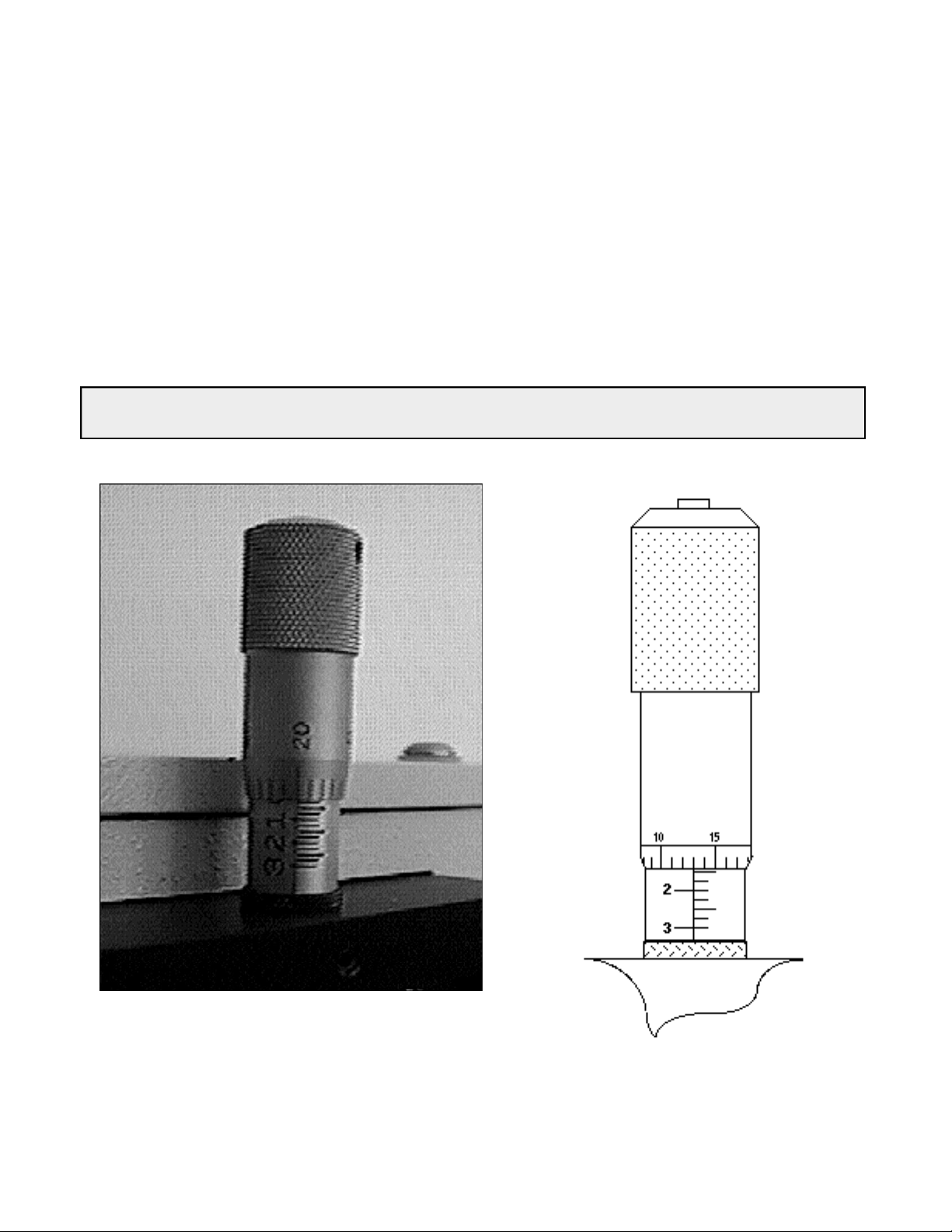
Note: Damage May Be Done If Slit Jaws Are Opened Wider Than
3.0mm.
Model 716 Bilateral
Slit:
Width Adjustments
The slit width of each bilateral slit assembly (716 type) is adjustable from 0.010 millimeters to 3
millimeters (10µm to 3,000µm) by a micrometer located on the top of the slit housing. The micrometer
knob is graduated in 0.010 millimeter (10µm) increments.
Each clockwise revolution of the micrometer knob increases the slit width 0.25 millimeters (250µm). For
maximum reproducibility, the slit width should be set in a clockwise direction (increasing slit widths)
each time it is changed. Refer to the drawing below.
The micrometer knob should not be rotated below a reading of 0.00 or above 3.00. A micrometer setting
of less than 0.010 millimeters (10µm) should not be used, because a stop is provided to prevent the slit
jaws from contacting each other.
Slit Width Setting: 200 Micrometers (0.200mm)
Slit Width
Setting:
1380
Micrometers
(1.38mm)

13
HRS-300 Operation
A.
Initialization
When power is turned ON to the HRS-300, it initializes to a wavelength of 0.0nm for grating number one.
If the power is switched OFF and then ON again to the HRS-300, it will re-initialize. Initialization gives the
system a reference, or starting position to keep track of wavelength position, grating location, and other
parameters. Alternative start-up parameters can be programmed if the factory defaults are not suitable (See
Appendix A). When the HRS-300 initializes, it also identifies the turret installed. This information is used by
optional LightField software to set up the correct operating parameters.
B.
Operating the
HRS-300
Using a
Computer
The HRS-300 can be controlled by terminal emulation or by computer using USB or RS232. The same
command set listed below can be used for both USB and RS232 connections.
Commands can be sent as single commands or grouped in strings of commands. All commands are single
words (contain no spaces) and all commands in a string are separated by at least one space. Parameters, if
needed, precede the command and are separated from the command by at least one space (e.g. 546.7
GOTO).
For RS232 operation, the port set-up is 9600 baud, 8 data bits, 1 stop bit and no parity. All commands or
strings of commands must be terminated with a carriage return (0D hex). The HRS-300 responds to a
command when the command has been completed by returning the characters OK followed by carriage
return and line feed (hex ASCII sequence 20 6F 6B 0D 0A). The default condition is to echo each character
that is sent to the HRS-300.
Monochromator
Wavelength
Movement Commands:
GOTO Goes to a destination wavelength at maximum motor speed. Accepts destination
wavelength in nm as a floating-point number with up to 3 digits after the decimal
point or whole number wavelength with no decimal point.
<GOTO> Same as GOTO (For compatibility with software written for previous SpectraPro
models.)
NM Goes to a destination wavelength at constant nm/min rate specified by last NM/MIN
command. Accepts destination wavelength in nm as a floating-point number with up
to 3 digits after the decimal point or whole number wavelength with no decimal point.
<NM> Same as NM (For compatibility with software written for previous SpectraPro models.)

14
Monochromator
Wavelength
Movement
Commands (continued)
:
>NM Similar to NM except it returns control to user immediately rather than waiting for
completion of monochromator wavelength move. Can be used with ?NM or
MONO-?DONE below. This command must be terminated with MONO-STOP listed
below. NOTE: Use the NM command when communication with the
monochromator during the scan is not required.
?NM Returns present wavelength in nm to 0.01nm resolution with units nm appended.
E.G. ?NM 300.00 nm
MONO-?DONE Used with >NM command to determine if monochromator has reached the destination.
Returns 0 if move is not complete, 1 if move is complete.
MONO-STOP Stops the monochromator wavelength move after use of the >NM command.
NM/MIN Returns present scan rate in nm/min to 0.01 nm/min resolution with units nm/min
appended.
E.G. ?NM/MIN 100.00 nm/min
Grating Control
Commands:
GRATING Places specified grating in position to the wavelength of the wavelength on the present
grating. Up to nine (9) gratings are allowed on three (3) turrets. This command takes
a grating number from 1 - 9. IMPORTANT NOTE: This command assumes that the
correct turret is specified by the TURRET command. For example, using grating
numbers 1, 4 and 7 will place the first grating on the installed turret into that
position and call up the parameters for the grating number specified.
?GRATING Returns the number of gratings presently being used numbered 1 - 9.
?GRATINGS Returns the list of installed gratings with position groove density and blaze.
The present grating is specified with an arrow.
TURRET Specifies the presently installed turret or the turret to be installed.
E.G. If installing the second turret, issue the command 2 TURRET to insure using
the correct parameters.
?TURRET Returns the correctly installed turret numbered 1 - 3.
Diverter Mirror Control
Commands:
EXIT-MIRROR Designates the exit diverter mirror to receive the diverter control commands. This
command is for HRS spectrographs that can accept two diverter mirrors (HRS-500
and HRS-750). HRS-300 spectrographs will accept this command but it is not
required.

15
ENT-MIRROR Designates the entrance diverter mirror to receive the diverter control commands.
This command is for HRS spectrographs that can accept two diverter mirrors.
The SP-300i monochromators will not accept this command.
FRONT Moves the designated diverter mirror to position the beam to the front port position.
SIDE Moves the designated diverter mirror to position the beam to the side port position.
?MIRROR Returns the position of the designated diverter mirror with the responses
“front”
and
“side”.
?MIR Returns the position of the designated diverter mirror with the responses 0 for front
and 1 for side.
Slit Width Control
Commands (motorized slits only):
FRONT-EXIT-SLIT
Designates front exit slit to receive slit control commands. NOTE: The designation
remains in effect until changed by another slit designator. This command does not
have to be repeated until the designated slit is changed.
SIDE-EXIT-SLIT Designates side exit slit to receive slit control commands.
FRONT-ENT-SLIT Designates front entrance slit to receive slit control commands.
SIDE-ENT-SLIT Designates side entrance slit to receive slit control commands.
MICRONS Sets the slit width for the designated slit in the range of 10 to 3000 microns to 1
micron resolution.
?MICRONS Returns the slit width setting in microns to the nearest 1 micron.

16
GRATING CALIBRATION COMMANDS:
INIT-OFFSET Sets the offset value for the designated grating. Default values are 0 for gratings 1, 4
and 7; 1536000 for gratings 2, 5 and 8; and 3072000 for gratings 3, 6, and 9. The
limits on the settings are +/- 2500 for a 1200 g/mm grating. This corresponds to an
error of greater than +/- 5nm for a 1200 g/mm grating. The limits are adjusted for
grating groove density, e.g. error for a 600 g/mm grating is +/- 5000. The grating
density designator used with this command is grating# - 1.
E.G. 3072056. 8 INIT-OFFSET for setting offset on grating #9 - 3rd grating on
turret #3.
NOTE: This command requires a decimal point after the offset value.
INIT-GADJUST Sets grating adjustment value for the designated grating. Default values are 10000 for
all gratings. The limits on the parameter for this command are +/- 1000 for all
gratings. The grating designator used with this command is the grating # - 1.
E.G. 9993 1 INIT-GADJUST for setting GADJUST on the second grating of turret #1.
NOTE: This command is to maintain compatibility with previous SpectraPro
applications. For new applications, use the INIT-SP300-GADJUST command below.
MONO-EESTATUS Returns setup and grating calibration parameters for all gratings.
RESTORE
FACTOR
Y
SETTINGS Returns all parameters including grating calibration parameters to the original factory
calibrated settings. NOTE: This command will overwrite any calibration parameters
set by the user.
MONO-RESET Initializes SpectraPro monochromator. Necessary after using INIT-OFFSET,
INIT-GADJUST or INIT-SP300-GADJUST.
HELLO Same as MONO-RESET. Used to maintain compatibility with existing applications.
MODEL Returns model number of the spectrograph/monochromator.
E.G. MODEL HRS-300-S
SERIAL Returns serial number of HRS spectrograph/monochromator. Format is 7 digits with
the first 3 digits being the model #. E.G. SERIAL 3060232
The following are the Start-Up parameters and their default values:
Default Values:
TURRET #1
GRATING #1
WAVELENGTH 0.0 nm
SCAN SPEED 100.0 nm/min

17
INIT-GRATING Selects which of the three gratings on the installed turret the SpectraPro will go
to after finding 0.0 nm on the first grating of the installed turret.
E.G. 2 INIT-GRATING selects the second grating as the default. Accepts values 1 -
9.
INIT-WAVELENGTH Sets an initial wavelength for the SpectraPro after initialization.
E.G. 435.84 INIT-WAVELENGTH
INIT-SRATE Sets an initial scan rate for the SpectraPro.
E.G. 500.0 INIT-SRATE

18
C.
Focusing and
Alignment
of Array
Detectors
With the array detector properly mounted to the HRS-300, use the following procedure to align and focus
the array detector to the HRS-300 optical system. It assumes that the array detector is mounted to the
HRS-300 and running for the following procedure.
1. Mount a light source such as a mercury pen-ray type to the entrance slit of the HRS-
300. PI offers a standard Mercury/Neon-Argon lamp, IntelliCal, designed for this
purpose. Any light source with line output can be used for focus. If there are no “line”
sources available, it is possible to use a broadband source such as tungsten for the
alignment. If this is the situation, use a wavelength setting of 0.0nm for alignment
purposes.
2. With the HRS-300 properly connected to the computer, turn the power ON and move the
spectrograph to a wavelength of 546.074nm if using a mercury lamp, or 0.0 nm for a
broadband source, or another wavelength corresponding to a known peak produced by
another “line” source.
3. With the array detector operating, check the image of the light source if running in
an imaging mode with a CCD. Otherwise check the line intensity and shape.
4. Using a 9/64th Allen wrench, loosen the split clamp screw approximately ½-turn and
slowly slide the array detector IN or OUT until the sharpest image is achieved, or the
sharpest line is achieved. There is a focus stop thumb wheel screw included at each exit
port to assist in fine focus adjustments as well as rotational alignment of the camera to
the HRS-300.
5. Move the thumb wheel until it just makes contact with the array detector mounting flange.
This enables you to rotate the detector without changing the focus position. Rotate the
detector for correct alignment of the slit image to the CCD. Optional LightField software
includes an “align spectrometer” function for this purpose. The thumb wheel
adjustments may be used to precisely position the detector - one eighth of a turn of the
thumb wheel changes the detector position by approximately 1/10th of a millimeter.
6. After each adjustment, ensure the array detector mounting flange is in contact with the
thumb wheel. Tighten the split clamp to secure the detector in position when sharpest
focus has been achieved.
7. The light source can be removed if desired and replaced by fiber optics or other light sources.
8. If fibers or other imaging optics are used to bring light into the HRS-300, they may
require adjustment along the optical axis to achieve best vertical image qualit

19
Appendices and Schematic
Drawings
Appendix 1:
Selecting
Alternate Start-Up
Parameters
The following are the Start-Up parameters and their default values:
GRATING #1
WAVELENGTH 0.0 nm
SCAN SPEED 100.0 nm/min
Each of the above may be changed through the RS232 port or IEEE488 port using the following
commands. These values are stored in non-volatile memory and will be in effect after the next power-up.
INIT-GRATING Selects which of the two gratings on the installed turret the HRS-300 will go to after
finding 0.0 nm on the first grating.
E.G. 2 INIT-GRATING selects the second grating as the default
INIT-WAVELENGTH Sets an initial wavelength for the HRS-300 after initialization.
E.G. 435.84 INIT-WAVELENGTH Notice that two digits after the decimal point are
required
INIT-SRATE Sets an initial scan rate for the HRS-300.
E.G. 500.00 INIT-SRATE Notice that two digits after the decimal point are required
The following command is used to return all grating parameters and start-up parameters to the original
factory settings.
Note that any gratings installed at a later date (after initially receiving the HRS-300) will be erased from
memory using this “restore command”.
RESTORE-FACTORY-SETTINGS Returns all parameters, including grating calibration parameters, to the
original factory calibrated settings. NOTE: This command will overwrite
any calibration parameters set by the user.

20
Appendix 2: HRS Outline Drawing
Table of contents
Other Princeton Instruments Measuring Instrument manuals

Popular Measuring Instrument manuals by other brands


Analytical Technology
Analytical Technology Q46H/62-63 manual

National Instruments
National Instruments MON-10467 user guide

ARAG
ARAG alfa 310S Installation

Sokkia
Sokkia X-1000 series Operator's manual

GROCO
GROCO SSA-3 Series Installation and operating instructions

Fluke
Fluke PG7607 Operation and maintenance manual