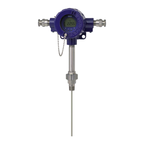
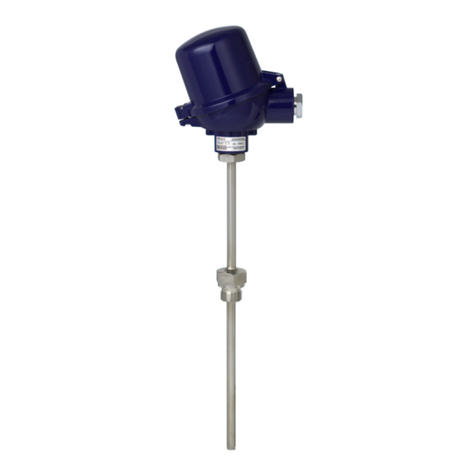
WIKA TC82 Operating instructions

EN
DE
Additional operating instructions
Zusatz-Betriebsanleitung
Additional operating instructions
for hazardous areas (Ex i)
Models TC82, TC83
Zusatz-Betriebsanleitung für explosionsgefährdete Bereiche (Ex i)
Typen TC82, TC83
BVS 20 ATEX E 044 X
IECEx BVS 20.0033X
Models TC82-F Models TC83-F

EN
DE
2
14302224.01 01/2023 EN/DE
Additional operating instructions TC82, TC83, intrinsically safe designs (Ex i)
© 01/2023 WIKA Alexander Wiegand SE & Co. KG
All rights reserved. / Alle Rechte vorbehalten.
WIKA®is a registered trademark in various countries.
WIKA®ist eine geschützte Marke in verschiedenen Ländern.
Prior to starting any work, read the operating instructions!
Keep for later use!
Vor Beginn aller Arbeiten Betriebsanleitung lesen!
Zum späteren Gebrauch aufbewahren!
Additional operating instructions
models TC82,
TC83 (Ex i) Page 3 - 20
Zusatz-Betriebsanleitung Typen TC82, TC83 (Ex i) Seite 21 - 38

EN
14302224.01 01/2023 EN/DE
Additional operating instructions TC82, TC83, intrinsically safe designs (Ex i) 3
Contents
Contents
Declarations of conformity can be found online at www.wika.com.
1. Ex marking 4
2. Safety 6
3. Commissioning, operation 8
4. Special conditions for use (X conditions) 15
5. Measures to reduce the risk of ignition 18
Annex: EU declaration of conformity 20

EN
14302224.01 01/2023 EN/DE
Additional operating instructions TC82, TC83, intrinsically safe designs (Ex i)4
1. Ex marking
DANGER!
Danger to life due to loss of explosion protection
Non-observance of these instructions and their contents may result in the loss
of explosion protection.
▶Observe the safety instructions in this chapter and further explosion
instructions in these operating instructions.
▶Follow the requirements of the ATEX directive.
▶Observe the information given in the applicable type examination certificate
and the relevant regulations for installation and use in hazardous areas (e.g.
IEC 60079-11, IEC 60079-10 and IEC 60079-14).
Check whether the classification is suitable for the application. Observe the relevant
national regulations.
Models series TC82-F-*IL or TC83-F-*IL (gas application)
Variant Electrical
data
Temperatures Marking
Ambient 1) Temperature
class
Variant 1:
Empty
enclosure
Ui= DC 30 V
Ii= 110 mA
Pi= 500 mW
Li, Ci= negligible
-40 … +85 °C
-60 … +85 °C
T5 ...T1 II 2/-G Ex ia IIC T*(2) Gb/-
-40 … +80 °C
-60 … +80 °C
T6 II 2/-G Ex ia IIC T6 Gb/-
Variant 2:
Empty
enclosure +
electronic
See electronics 3) See electronics 3) See electronics 3) II 2/-G Ex ia IIC T*(2) Gb/-
Variant 3:
Field
transmitter
See transmitter 3) See transmitter 3) See transmitter 3) II 2/-G Ex ia IIC T*(3) Gb/-
1) For variant 1 and 2:The low ambient temperature -40 °C applies to models with Limatherm or Rosemount cases.The low ambient
temperature of either -40 °C or -60 °C applies to models with WIKA connection head series 1/4000, 5/6000, 7/8000. For explanation
of symbols for low temperature range see chapter 2.5 “Labelling, safety marks”
2) The temperature class depends on the ambient temperature.
3) The parameters for variant 2 and variant 3 Transmitters have to be taken out of the related operating instructions.
1. Ex marking
Supplementary documentation:
▶This additional information for hazardous areas applies in conjunction with the
operating instructions “High-temperature thermocouples, models TC80, TC82, TC83
Calitum®, TC84“ (article number 14486177).

EN
14302224.01 01/2023 EN/DE
Additional operating instructions TC82, TC83, intrinsically safe designs (Ex i) 5
Models series TC82-F-*IO or TC83-F-*IO (gas and dust application)
Variant Electrical
data
Temperatures Marking
Ambient 1) Temperature
class
Variant 1:
Empty
enclosure
Ui= DC 30 V
Ii= 110 mA
Pi= 500 mW
Li, Ci= negligible
-40 … +85 °C
-60 … +85 °C
N/A II 2/-G Ex ia IIC T*(2) Gb/-
II 2/-D Ex ia IIIC T135 °C Db/-
Variant 2:
Empty
enclosure +
electronic
See electronics 3) See electronics 3) See electronics 3) II 2/-G Ex ia IIC T*(2) Gb/-
II 2/-D Ex ia IIIC T* Db/-
Variant 3:
Field
transmitter
See transmitter 3) See transmitter 3) See transmitter 3) II 2/-G Ex ia IIC T*(3) Gb/-
II 2/-D Ex ia IIIC T*(3) Db/-
1) For variant 1 and 2:The low ambient temperature -40 °C applies to models with Limatherm or Rosemount cases.The low ambient
temperature of either -40 °C or -60 °C applies to models with WIKA connection head series 1/4000, 5/6000, 7/8000. For explanation
of symbols for low temperature range see chapter 2.5 “Labelling, safety marks”
2) The temperature class depends on the ambient temperature.
3) The parameters for variant 2 and variant 3 Transmitters have to be taken out of the related operating instructions.
When there is a built-in transmitter and/or a digital display, the special conditions from the
type examination certificate (see chapter 4 “Special conditions for use (X conditions)”)
apply.
1. Ex marking

EN
14302224.01 01/2023 EN/DE
Additional operating instructions TC82, TC83, intrinsically safe designs (Ex i)6
2. Safety
2.1 Explanation of symbols
WARNING!
... indicates a potentially dangerous situation that can result in serious injury or
death, if not avoided.
DANGER!
... indicates a potentially dangerous situation in the hazardous area that can
result in serious injury or death, if not avoided.
2.2 Intended use
The thermometers described here are suitable for temperature measurement in hazardous
areas like e.g. sulphur recovery units (SRU).
The electrical thermometer model TC82-F-*I* or TC83-F-*I* is made of a module (model
TC8x-M), which is fitted to an suitable case.
The cases shall either come along with their own IECEx/ATEX certification or they shall
comply to the minimum requirements.
IP protection:
At least IP20 for gas hazardous environments and at least IP6X for dust hazardous
environments. For types with a transmitter installed, the specification in the transmitters
certificate shall be followed. Light metal enclosures, however, shall be suitable in
accordance with EN/IEC 60079-0 clause 8. Non-metal enclosures or powder-coated
enclosures shall additionally comply with the electrostatic requirements of EN/IEC 60079-0
or have a corresponding warning marking. Refer to the section „Specific conditions for safe
use“ for Ex i models (no. 1 and no. 2).
The module TC82-M, TC83-M consists of the flange assembly with ceramic tubes, all
parts of electrical insulation of the thermocouple wires and a gas-tight bushing to limit the
flameproof area and the intrinsically safe area.
The sensing part of the module is made of ceramic insulated thermocouple wires.
3 different variants of thermometers TC82-F-*I* or TC83-F-*I* are available:
■Variant 1:The thermometer (module) model TC82-M or TC83-M is fitted to a suitable
case.Terminals are mounted inside the case.
■Variant 2:The thermometer (module) model TC82-M or TC83-M is fitted to a suitable
case. Electronic equipment is mounted inside the case.
■Variant 3:The thermometer (module) model TC82-M or TC83-M is fitted to a certified
apparatus (transmitter) in the type of protection “Intrinsically safe”.
The module TC82-M, TC83-M is designed to fit to a suitable enclosure by the end user.
2. Safety

EN
14302224.01 01/2023 EN/DE
Additional operating instructions TC82, TC83, intrinsically safe designs (Ex i) 7
The module is marked without temperature class, either with II 2/-G Ex ia IIC Gb/- or
additionally with II 2/-D Ex ia IIIC Db/-. All conditions and limitations described for the
variants 1 to 3 apply to this combined equipment.The responsibility rests to the operator.
The non-observance of the instructions for use in hazardous areas can lead to the loss
of the explosion protection. Adhere to the following limit values and instructions (see data
sheet).
War
2.3 Responsibility of the operator
The responsibility for classification of zones lies with the plant operator and not the
manufacturer/supplier of the equipment.
2.4 Personnel qualification
The skilled electrical personnel must have knowledge of ignition protection types,
regulations and provisions for equipment in hazardous areas.
2.5 Labelling, safety marks
Additional product label (example)
Approval-related data
Symbol for the usability of the instrument in ambient temperatures down to
-60 °C [-76 °F].
TÜV 10 ATEX 555793 X
IECEx TUN 10.0002X
II 2 G Ex ib IIC T1 ... T6 Gb
Tamb see manual
********ATEX ******
IECEx ************
II 2/-G Ex db IIC T6 ... T1 Gb/-
Tamb see manual
WARNING! DO NOT OPEN WHILE ENERGIZED!
Ex d
Ex i
2. Safety

EN
14302224.01 01/2023 EN/DE
Additional operating instructions TC82, TC83, intrinsically safe designs (Ex i)8
3. Commissioning, operation
DANGER!
Danger to life from explosion
Through working in flammable atmospheres, there is a risk of explosion which
can cause death.
▶Only carry out set-up work in non-hazardous environments!
▶Do not open the instrument while under voltage.
DANGER!
Danger to life from explosion
By using a measuring insert without a suitable connection head (case), an
explosion risk occurs which can cause fatalities.
▶Only use the measuring insert in the connection head designed for it.
DANGER!
Danger to life due to loss of explosion protection
If the corresponding tightening torques are not observed, this can lead to a
loss of the explosion protection.
▶Ensure the tightening torques in accordance with chapter 3.2.
WARNING!
Damage to the measuring instrument by operation outside the upper or
lower limits of the operating temperature
Failure to observe the permissible operating temperature, also taking into
account convection and radiation, can even cause damage to the thermometer
during mounting.
▶The upper and lower limits of the specified operating temperature range
must not be exceeded.
WARNING!
Potential electrostatic charging hazard
There is a risk of electrostatic discharges for group IIIC EPL Db.
▶For application in areas requiring EPL Db equipment and in areas with
high or repeated charging processes, special protective measures must be
taken.
Observe the special conditions (see chapter 4 “Special conditions for use (X conditions)”).
3. Commissioning, operation

EN
14302224.01 01/2023 EN/DE
Additional operating instructions TC82, TC83, intrinsically safe designs (Ex i) 9
3. Commissioning, operation
3.1 Mechanical mounting
3.1.1 Parallel threads
If the thermometer connection head, neck tube, protection tube or process connection are
connected with parallel threads (e.g. G ½, M20 x 1.5 ...), these threads must be secured
using seals which prevent liquids from penetrating into the thermometer.
As standard, WIKA uses copper seals for the connection between the neck tube and the
protection tube, and a paper flat gasket for the connection of the connection head and the
neck tube or protection tube.
If the thermometer and the protection tube are already connected, the seals will already be
mounted (if ordered).The plant operator must check whether the seals are suitable for the
operating conditions and must replace them, if necessary, with suitable seals (see chapter
11 “Accessories” in the operating instructions “High-temperature thermocouples, models
TC80, TC82, TC83 Calitum®, TC84“ (article number 14486177)).
Seals must be replaced after dismounting!
3.1.2 Tapered threads
With NPT or other tapered threads, it should be checked whether it may be necessary
to seal them additionally with PTFE tape or hemp.The threads must be lubricated with a
suitable lubricant before fitting.

EN
14302224.01 01/2023 EN/DE
Additional operating instructions TC82, TC83, intrinsically safe designs (Ex i)10
3. Commissioning, operation
3.2 Tightening torques
■Only ever screw in, or unscrew, the instrument via the spanner flats and to the
prescribed torque using an appropriate tool.
■The correct torque depends on the dimensions of the connection thread and the sealing
used (form/material).
■When screwing in or unscrewing the instrument, do not use the connection head as
contact surface.
■When screwing in the instrument, please observe that the threads are not skewed.
■Assure that the purge gas connection is tighten and no gas can escape, so that there is
no carry-through between zones.
Connection head, selectable (example)
Thread Tightening torques in Nm
Connection head material
Aluminium Stainless steel
½ NPT T.F.F.T 2 - 3 1) T.F.F.T 2 - 3 1)
¾ NPT T.F.F.T 2 - 3 1) T.F.F.T 2 - 3 1)
M20 x 1.5 with counter nut 23 25
M24 x 1.5 with counter nut 27 30
Thread Tightening torques in Nm
Connection head material
Aluminium Stainless steel
¼ NPT T.F.F.T 2 - 3 1) T.F.F.T 2 - 3 1)
Tightening torques between connection head and neck tube
Tightening torques between purge connection and purge piping
1) Turns from finger tight (T.F.F.T)

EN
14302224.01 01/2023 EN/DE
Additional operating instructions TC82, TC83, intrinsically safe designs (Ex i) 11
3.3 Locking screw
Always tighten the locking screw to prevent unintended opening
of the head with flameproof enclosure.
Before opening the head, always loosen the locking screw
sufficiently.
3.4 Electrical mounting
Using a transmitter/digital display (option):
Observe the contents of the operating instructions for the transmitter/digital display (see
scope of delivery).
Built-in transmitters/digital displays have own certificates. For instruments with built-in
transmitter or digital display, the permissible ambient temperature ranges specified in their
certificates also apply to the entire instrument.
Cable glands
Requirements for meeting ingress protection:
■Only use cable glands within their indicated clamping area (cable diameter suitable for
the cable gland).
■Do not use the lower clamping area with very soft cable types.
■Only use round cables (if necessary, slightly oval in cross-section).
■Do not twist the cable.
■Repeated opening/closing is possible; however only if necessary, as it might have a
detrimental effect on the ingress protection
■For cable with a pronounced cold-flow behaviour the gland must be fully tightened.
Cable glands affects the permissible ambient temperature. Refer to the related
table “Cable entry”
3. Commissioning, operation

EN
14302224.01 01/2023 EN/DE
Additional operating instructions TC82, TC83, intrinsically safe designs (Ex i)12
3.5 Cable entry
Cable entry Colour Ingress
protection
(max.) IEC/
EN 60529 1)
Cable
entry
thread
size
Min./max.
ambient
temperature
Standard cable entry 2) Natural
finish
IP65 ■M20 x 1.5
■½ NPT
-40 ... +80 °C
Plastic cable gland
(cable Ø 6 ... 10 mm) 2) Black
Grey
IP66 3) ■M20 x 1.5
■½ NPT
-40 ... +80 °C
Plastic cable gland
(cable Ø 6 ... 10 mm),
Ex e 2)
Light blue
Black
IP66 3) ■M20 x 1.5
■½ NPT
■-20 ... +80 °C
■-40 ... +70 °C
Nickel-plated
brass cable gland
(cable Ø 6 ... 12 mm)
Natural
finish
IP66 3) ■M20 x 1.5
■½ NPT
-60 4) / -40 ... +80 °C
Nickel-plated
brass cable gland
(cable Ø 6 ... 12 mm),
Ex e
Natural
finish
IP66 3) ■M20 x 1.5
■½ NPT
-60 4) / -40 ... +80 °C
Stainless steel cable
gland
(cable Ø 7 ... 12 mm)
Natural
finish
IP66 3) ■M20 x 1.5
■½ NPT
-60 4) / -40 ... +80 °C
Stainless steel cable
gland
(cable Ø 7 ... 12 mm),
Ex e
Natural
finish
IP66 3) ■M20 x 1.5
■½ NPT
-60 4) / -40 ... +80 °C
1) IP ingress protection of the cable gland.
2) Not available for BVS connection head
3) Ingress protections, describing temporary or permanent immersion, on request
4) Special version on request (explosion-protected versions only available with specific approvals)
3.6 Electrical connection
CAUTION!
Danger of short-circuit
Damage to cables, wires and connection points can lead to malfunction of the
instrument.
▶Avoid damaging the cables and wires. Fine-stranded leads with bare ends
must be finished with end splices.
3. Commissioning, operation

EN
14302224.01 01/2023 EN/DE
Additional operating instructions TC82, TC83, intrinsically safe designs (Ex i) 13
3.6.1 Thermocouples with B-type terminal terminal block (ceramic)
Only 1xTC permitted
3.6.2 Thermocouples with 7/8000-type terminal terminal block (1210G6GNCX)
+
-
>3
>3
1xTC
+
-+
-
+
-
>6
1xTC 2xTC
>3
>3
>3
>3
3. Commissioning, operation

EN
14302224.01 01/2023 EN/DE
Additional operating instructions TC82, TC83, intrinsically safe designs (Ex i)14
3.6.3 Thermocouples with 1/4000-type terminal terminal block (1210G6GNCX)
3.6.4 Colour code of cable strands
Type of sensor IEC 60584-1 ASTM E230
Positive Negative Positive Negative
KGreen White Yellow Red
JBlack White White Red
EViolet White Violet Red
NPink White Orange Red
TBrown White Blue Red
3.7 Temperature carry-over from the process
A heat backflow from the process that exceeds the operating temperature of the transmitter
(digital display) or case is not permitted and must be prevented by installing suitable heat
suitable heat insulation or a respectively long neck tube.
+
-+
-
+
-
>3
>3
>3
>6
1xTC 2xTC
3. Commissioning, operation

EN
14302224.01 01/2023 EN/DE
Additional operating instructions TC82, TC83, intrinsically safe designs (Ex i) 15
4. Special conditions for use (X conditions)
1) For the use of enclosures they shall either come along with their own IECEx/ATEX
certification or they shall comply to the minimum requirements.
IP protection: at least IP20 for gas hazardous environments and at least IP6X for dust
hazardous environments.
For types with a transmitter installed, the specification in the transmitters certificate
shall be followed. Light metal enclosures, however, shall be suitable in accordance with
EN/IEC 60079-0 clause 8. Non-metal enclosures or powder-coated enclosures shall
additionally comply with the electrostatic requirements of EN/IEC 60079-0 or have a
corresponding warning marking.
2) The used transmitters/digital displays shall be provided with their own IECEx/ATEX
certification in accordance to EN/IEC 60079-0 and EN/IEC 60079-11. It shall have
at least type of protection “ia” and shall be appropriate for EPL Gb or EPL Db.The
installation conditions or specific conditions of use, the electrical connection values, the
temperature class respectively the maximum surface temperatures of devices for the
use in explosive dust atmospheres and the permissible ambient temperature shall be
taken from the corresponding certification and shall be considered.
3) For devices that do not comply with the electrostatic requirements of IEC 60079-0
electrostatic charging shall be avoided.
4) A prohibited heat reflux from the process has to be prevented for instance by heat
insulation or using an extended neck tube. A prohibited heat reflow occurs if the heat
out of the process exceeds the service temperature of the enclosure or the temperature
class.
5) Accessible parts of metal enclosures which are not connected to ground and accessible
parts of metal enclosures which are connected to ground but do not comply to clause
6.5 of IEC/EN 60079-11, shall comply with clause 7.5 of IEC/EN 60079-0 or have a
corresponding warning marking.
6) In case it is impracticable to include the ambient temperature range within the
marking of the instrument, because the instrument is a small instrument according
to 29.11 of IEC/EN 60079-0, the ambient temperature range shall be specified in the
supplied manual. If the instrument is not a small instrument according to 29.11 of
IEC/EN 60079-0 and the ambient temperature range is not included within the marking,
the marking shall additionally include an advisory marking referring to the supplied
manual.

EN
14302224.01 01/2023 EN/DE
Additional operating instructions TC82, TC83, intrinsically safe designs (Ex i)16
14294554.01
U: Insertion length / Einbaulänge
X: Support tube length below process connection /
Halterohrlänge unterhalb Prozessanschluss
Legend / Legende:
1. Connection head / Anschlusskopf
2. Neck tube / Halsrohr
3. Metal support tube / Metallisches Halterohr
4. Ceramic thermowell / Schutzrohr
5. Terminal block / Klemmsockel
6. Transmitter (option) / Transmitter (optional)
7. Field transmitter / Feldtransmitter
A (NL): Nominal length / Nennlänge
X
U
ØF4
ØF
A (NL)
2
10
2
10
10
10
4
3
9
8
2
4
3
9
8
11
4
3
9
2
8
4
3
9
8
X
U
ØF4
ØF
A (NL)
X
U
ØF4
ØF
A (NL)
X
U
ØF4
ØF
A (NL)
1
1
6
5
7
14294554.01
Basic module
Model TC83-M
Following specific conditions for safe use (x-conditions) applies
No. of
x-conditions
1
No. 1 Connection head
2
No. 4 Neck tube
3
N/A Metal support tube
4
N/A Ceramic protection tube
5
N/A Terminal block
6
No. 2 Transmitter (option)
7
No. 2 Field transmitter
8
N/A Process connection
9
N/A Purge (option) only TC82
10
N/A Marking per drawing 14343616
11
N/A Marking: Part of TC83-F; Serial number
- No. 3, no. 5, no. 6 Entire device respectively complete
assembly
Legend:
A (NL) Nominal length
U Insertion length
X Support tube length below process connection
14294554.01
U: Insertion length / Einbaulänge
X: Support tube length below process connection /
Halterohrlänge unterhalb Prozessanschluss
Legend / Legende:
1. Connection head / Anschlusskopf
2. Neck tube / Halsrohr
3. Metal support tube / Metallisches Halterohr
4. Ceramic thermowell / Schutzrohr
5. Terminal block / Klemmsockel
6. Transmitter (option) / Transmitter (optional)
7. Field transmitter / Feldtransmitter
A (NL): Nominal length / Nennlänge
X
U
ØF4
ØF
A (NL)
2
10
2
10
10
10
4
3
9
8
2
4
3
9
8
11
4
3
9
2
8
4
3
9
8
X
U
ØF4
ØF
A (NL)
X
U
ØF4
ØF
A (NL)
X
U
ØF4
ØF
A (NL)
1
1
6
5
7
14294554.01
Variant 1 without transmitter
Model TC83-F
Variant 2 with transmitter
Model TC83-F
Variant 3 with field transmitter
Model TC83-F
4. Special conditions for use (X conditions)

EN
14302224.01 01/2023 EN/DE
Additional operating instructions TC82, TC83, intrinsically safe designs (Ex i) 17
4.1 Overview of temperature zones and safety-related instructions for the different
variants
4.1.1 Variant 1
The thermometer (module) model TC82-M or TC83-M is fitted to a suitable enclosure.
Terminals are mounted inside the enclosure.
Marking: II 2/-G Ex ia IIC T* Gb/- or additionally with II 2/-D Ex ia IIIC T135 °C Db/-
The enclosure is in zone 1 (zone 21) or zone 2 (zone 22).The sensor is located in a non Ex
zone.
A heating in the enclosure does not occur with variant 1. However, an impermissible heat
backflow from the process which can exceed the operating temperature of the enclosure
or the temperature class, must be prevented through suitable heat insulation or a suitably
long neck tube.
4.1.2 Variant 2
The thermometer (module) model TC82-M or TC83-M is fitted to a suitable enclosure.
Electronic equipment is mounted inside the enclosure.
Marking: II 2/-G Ex ia IIC T* Gb/- or additionally with II 2/-D Ex ia IIIC T* Db/-
The enclosure is in zone 1 (zone 21) or zone 2 (zone 22).The sensor is located in a non Ex
zone.
14387940.01
TC82 TC83
Zone 1
Model TC82 Model TC83
Zone 1
T > 400 °C:
Non-Ex area
T > 400 °C:
Non-Ex area
4. Special conditions for use (X conditions)

EN
14302224.01 01/2023 EN/DE
Additional operating instructions TC82, TC83, intrinsically safe designs (Ex i)18
4.1.3 Variant 3
The thermometer (module) model TC82-M or TC83-M is fitted to a certified equipment
(field transmitter) in the type of protection “Intrinsically Safety”.
The position of the marking label for the complete assembly TC82-F or TC83-F is on the
neck tube.The original marking of the field transmitter remains unchanged.
4.1.4 Modules
The module TC82-M, TC83-M is designed to fit to a suitable enclosure by the end user. The
module is marked without temperature class on the neck tube. All conditions and limitations
described for the variants 1 to 3 apply to this combined equipment. The responsibility rests
to the operator. An operation without a suitable enclosure is not permitted.
4. Special conditions ... (X conditions) / 5. Measures to reduce ...
5. Measures to reduce the risk of ignition
Variant 1:
These variants are simple electrical apparatus in the definition of EN/IEC 60079-11 and
have no internal ignition source of their own. A heating in the enclosure cannot happen,
therefore a thermal ignition is avoided.
The relevant clearances and creepage distances for the terminals, 6 mm between separate
intrinsically safe circuits, 3 mm to grounded conductive parts, are ensured by using suitable
terminal blocks.The requirements for the enclosures are described in the section „Special
conditions for safe use“. Likewise the distance to hot surfaces. The resistive spark ignition
is avoided by the limitation of the input parameters (Ui, li and Pi).
The maximum current that can occur is less than 50 % of the maximum permissible short-
circuit-current, even for a factor of safety of 1.5.
■Inductive spark ignition:The internal inductance is negligibly small.
■Capacitive spark ignition: The internal capacitance is negligibly small.
Variant 2 and variant 3:
These variants are „assemblies“ (combined equipment) in the scope of the ATEX directive
respectively intrinsically safe electrical systems according to IEC60079-25.
Variant 2:
In this case, electronic equipment such as head-mounted temperature transmitters and/or
digital displays are installed in the enclosures.

EN
14302224.01 01/2023 EN/DE
Additional operating instructions TC82, TC83, intrinsically safe designs (Ex i) 19
Variant 3:
In this case, the thermometers (modules) are attached to field temperature transmitters.
These devices must have their own corresponding IECEx/ATEX certificate.
The used transmitters/digital displays shall be provided with their own IECEx/ATEX
certification in accordance to EN/IEC 60079-0 and EN/IEC 60079-11. It shall have at least
type of protection “ia” and shall be appropriate for EPL Gb or EPL Db.
The installation conditions or specific conditions of use, the electrical connection values,
the temperature class respectively the maximum surface temperatures of devices for the
use in explosive dust atmospheres and the permissible ambient temperature shall be taken
from the corresponding certification and shall be considered. Refer to the section „Specific
conditions for safe use“.
5. Measures to reduce the risk of ignition

EN
14302224.01 01/2023 EN/DE
Additional operating instructions TC82, TC83, intrinsically safe designs (Ex i)20
Annex: EU declaration of conformity
Other manuals for TC82
1
This manual suits for next models
3
Table of contents
Languages:
Other WIKA Measuring Instrument manuals

WIKA
WIKA TC52-M User manual

WIKA
WIKA DPT-10 User manual

WIKA
WIKA NS 63 User manual

WIKA
WIKA 821 User manual

WIKA
WIKA PG43SA-S User manual

WIKA
WIKA SENSeOR AMS01 User manual

WIKA
WIKA TR12 Series Operating instructions

WIKA
WIKA CPH6400 User manual

WIKA
WIKA FLC-2300 User manual

WIKA
WIKA 116.18.02 Series User manual

WIKA
WIKA 232.30.100 Operating instructions

WIKA
WIKA 1500 Series User manual

WIKA
WIKA mensor 9476 User manual

WIKA
WIKA 700.01 User manual

WIKA
WIKA Delta-plus User manual

WIKA
WIKA PG81 User manual

WIKA
WIKA 232.50.100 User manual

WIKA
WIKA TC82 Operating instructions

WIKA
WIKA FLC-608 User manual

WIKA
WIKA FLC-UFL Series User manual