Princeton PIGGY BACK EASY HITCH User manual

PIGGY BACK®Delivery System
EASY HITCH™ Truck/Trailer
3-Position Mounting Installation
Instruction Manual


PIGGY BACK®Delivery System
EASY HITCH™ Truck/Trailer
3-Position Mounting Installation
Instruction Manual
Manual Part No.: 625-253
Rev. 12/2004
Notice: The information in this manual was in effect at the time of printing. Princeton Delivery
Systems reserves the right to make improvements and changes in specifications or design, without
notice and without incurring obligation. Please check with your Princeton dealer for possible updates
or revisions.
955 West Walnut Street
Canal Winchester, OH 43110
(614) 834-5000
FAX: (614) 834-5001


IMPORTANT INFORMATION
The attached information provides suggested methods of mounting a Princeton PIGGY BACK®Delivery
System to a truck or trailer.
The truck manufacturer, truck body manufacturer, and/or the trailer manufacturer should be contacted for
information concerning load requirements and safe installation on their products.
The mounting methods described herein supersede any previous information.
This mounting assembly is covered by one or more of the following patents: 5,575,604 5,813,820 6,024,535.
While installing the Princeton PIGGY BACK®Delivery System mounting, the truck or trailer brakes must be
applied and wheels must be chocked so that no movement occurs.
The complete mounting system must be installed to provide proper mounting and to retain full PIGGY BACK®
Delivery System warranty.
Contact your State Highway Patrol for information concerning local load limits, width limits, and other limita-
tions.
All welding must be done by certified welders with qualification in accordance with AWS D1.1.
Disconnect battery cables on the PIGGY BACK®Material Handler and the truck/trailer before welding or bat-
tery explosion may occur.
Contact Princeton for information concerning any special applications that are outside the scope of this proce-
dure.
Contact Princeton if you have any questions about the mounting or operation of the PIGGY BACK®Delivery
System.
LIMITED WARRANTY
PRINCETON DELIVERY SYSTEMS WARRANTS THAT FOR INITIAL USE THIS VEHICLE IS FREE FROM
DEFECTS IN MATERIAL OR WORKMANSHIP. IF THIS VEHICLE IS DEFECTIVE UPON INITIAL USE,
CONTACT YOUR AUTHORIZED PRINCETON DEALER FROM WHOM IT WAS PURCHASED AND THE
VEHICLE WILL BE REPAIRED OF EXCHANGED FOR A NEW ONE. THIS WARRANTY EXCLUDES
DEFECTS OR DAMAGE DUE TO MISUSE OR NEGLECT.
THIS LIMITED WARRANTY GIVES YOU SPECIFIC LEGAL RIGHTS AND YOU MAY ALSO HAVE OTHER
RIGHTS THAT VARY FROM STATE TO STATE. THE FOREGOING WARRANTY IS IN LIEU OF ALL OTHER
WARRANTIES, EXPRESS OR IMPLIED, INCLUDING BUT NOT LIMITED TO THE IMPLIED WARRANTIES
OF MERCHANTABILITY AND FITNESS FOR A PARTICULAR PURPOSE. IN NO EVENT SHALL
PRINCETON DELIVERY SYSTEMS BE LIABLE FOR SPECIAL, INDIRECT, INCIDENTAL OR
CONSEQUENTIAL DAMAGES WHETHER CONTRACT, TORT OR NEGLIGENCE. AS WITH ALL HEAVY
MACHINERY, THE USE OF THIS VEHICLE IS POTENTIALLY DANGEROUS IF THE OPERATOR DOES
NOT EXERCISE PROPER OPERATOR PROCEDURES PROVIDED FOR YOU IN THE OPERATOR
MANUAL AND HAVE READ AND BEEN INSTRUCTED ON THE PROPER LOADING AND UNLOADING
PROCEDURE FOR THE PRINCETON PIGGY BACK®.


Contents
1 General Information 5
2 Installation Kits 7
3 Major Component Photos 8
4 Fork Supports 9
5 Main Installation 10
6 Safety Chains 13
7 Tire Pad Installation 14
8 Truck/Trailer 7-Pin Wiring 16
9 Safety Signs 18
10 Detail Drawing 19
11 Mount Installation Check 20
ADDENDUM
A Dump Bed 21

Dimensions
Axle Location Axles as far to rear as possible while leaving clearance for the PIGGY
BACK®front tires. A minimum dimension of 27" for D45 and PB50 (33” for
PB65, Z-Series and E-Series units) is recommended from the rear of the
tire to the rear of the bed, with a maximum dimension of 48".
Height The PIGGY BACK®be installed as high as possible to avoid contact with
the ground when driving the onto steep inclines, ramps, etc. The
minimum distance from the ground to the bottom of the truck or
trailer crossmember is 48”. Minimum recommended distance between the
front tires and the ground is 11" and between the rear tire and the ground
is 18".
Structural Bed side and rear members-minimum C6 x 10.5 pounds per foot.
Bed cross members-minimum C4 x 7.7 pounds per foot, 10-12"
center to center.
1
General Information
These illustrations describe the factory-approved methods of mounting a Princeton
PIGGY BACK®Delivery System to an owner's truck or trailer.
This section covers the general setup information on the PIGGY BACK®and truck or trailer.
NOTE: This information is necessarily general and is based on similar applications. Contact
Princeton and fill out a Mounting Application Form to assure your specific truck or trailer
application meets the requirements for installation of a Princeton PIGGY BACK®Delivery
System.
Figure 1
Dimensions (cont.)
ICC Bumper On trailers manufactured after 1-26-98, the ICC bumper may need to be
replaced with a certified bumper, similar to Sun Underride PN 103-114.
Electrical On most trucks or trailers, tail light buckets will need to be relocated.
Tail, clearance and identification lights should be mounted as high as
possible to allow the PIGGY BACK®to be raised as close to the bed
bottom as possible to meet minimum ground clearance requirements.
Lights should be no wider than 54” (outside edge to outside edge).
Always check to insure proper light operation before and after tail light
relocation.
License Plate The license plate bracket and light must be mounted such that they are
clearly visible when the unit is and is not on the truck.
Suspension Air-ride suspension system is recommended.
Overhang All overhang dimensions are with the rear wheel of the PIGGY BACK®
turned sideways.
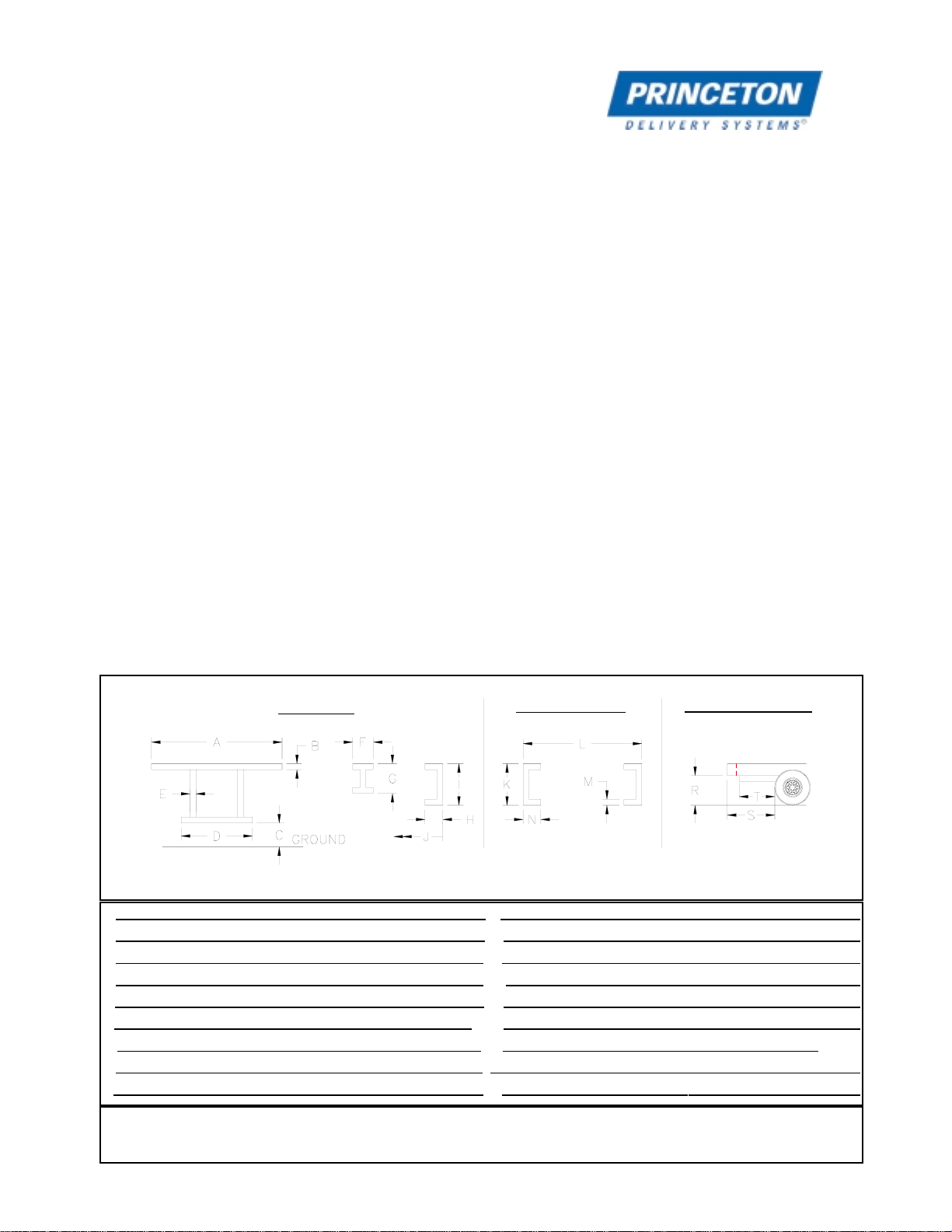
Truck/Trailer Bed and Chassis Specifications
Standard Dimensions For Straight Truck
A92’ min.-102” max.
B5” min.
C16” min.-22” max.
D53” max.
E3” min.
F2” min.
G4” min.-6” max.
H2.25” min.
I 6” min.-8” max.
J20’ min.
K10” min.
L34” min.
M3/8” min.
N3” min.
R48” min.
S_27” min. (D45 & PB50)_____ ____
33” min. - 48” max. (PB65, Z & E Series)
TFLUSH AT REAR
THE INFORMATION CONTAINED HEREIN IS PROPRIETARY TO PRINCETON DELIVERY SYSTEMS OR ONE OF ITS CUSTOMERS AND SHALL NOT BE
USED, DUPLICATED OR FURTHER DISSEMINATED FOR ANY PURPOSE OTHER THAN THAT FOR WHICH IT IS FURNISHED WITHOUT THE WRITTEN
CONSENT OF PRINCETON DELIVERY SYSTEMS.
Bed DataChassis DataClearance Data
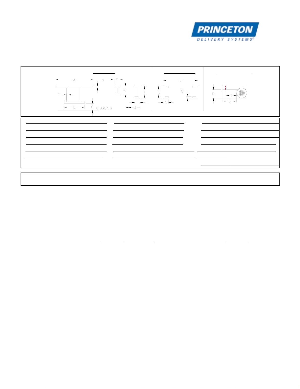
Dimensions (cont.)
Standard Dimensions For Trailer
A92’ min.-102” max.
B6” min.-8” max.
C16” min.-22” max.
D53” max.
E3” min.
F2” min.
G4” min.-6” max.
H
I
J
K10” min.
L38” min.-44” max.
M3/8” min.
N4” min.
R48” min.
S27” min.(D45 & PB50) ____
_33” min.-48” max. (PB65, &
__E-Series)
TFLUSH AT REAR
Bed DataChassis DataClearance Data
THE INFORMATION CONTAINED HEREIN IS PROPRIETARY TO PRINCETON DELIVERY SYSTEMS OR ONE OF ITS CUSTOMERS AND SHALL NOT BE USED,
DUPLICATED OR FURTHER DISSEMINATED FOR ANY PURPOSE OTHER THAN THAT FOR WHICH IT IS FURNISHED WITHOUT THE WRITTEN CONSENT OF
PRINCETON DELIVERY SYSTEMS.
2
Installation Kit A complete mounting kit as described below is available from Princeton
Delivery Systems.
P90.1070Easy Hitch, 3 Position, Mounting Kit
Parts List Item Description Quantity
P80.07B Kit, 7 Pin Trailer Receptacle 1
P90.321A Tubing, Mount Kit 2
P10.376C Chain Loop 2
P90.291B Chain Assembly 2
P90.1073 Kit, Front Tire Pad Mtg. 1
P90.1067C Weldment, Hanger Plate 2
P90.292A Gusset, Hanger Plate 6
P90.269B Gusset 8
P90.1069B Bed Strengthener 2
P90.303B Shaft, Hook Mtg. 2
118-115 Snap Ring, 2" Dia. 4
402-108 Hitch Pin 2
604-190 Decal, Patent in Process 3
604-127 Decal, PIGGY BACK® Transport 1
604-143 Safety Sign Warning 1
604-152 Safety Sign, Warning Mounting 1
604-125 Safety Sign, Pinch Point 4
Optional items that can be purchased
103-114 Sun Underride Protection Asm. 1
P10.970B Hook Right (Weld To Older, D5000 & Dump Units) 1
P10.969B Hook Left (Weld To Older, D5000 & Dump Units) 1

Tire Pad Kit P/N P90.1073 (1) Gusset P/N P90.269B (8) Wire Harness P/N P80.07B (1)
Weldment, Hanger Plate P/N P90.1067C (2) Shaft P/N P90.303B (2) Chain Loop P/N P90.376C (2)
Safety Chain P/N P90.291B (2) Retaining Ring P/N 118-115 (4) Hitch Pin P/N 402-108 (2)
3
Major Component Photos
Bed Strengthener P/N P90.1069B (2)

4
Fork Supports
EASY HITCH™ Only one method of fork supports is approved with the Easy
Hitch™ mounting system. The Transverse Mount uses two 2” x 4”
rectangular tubes parallel to the truck axle. This method can be
used on PIGGY BACK®Delivery Systems with block forks or
pallet forks.
Material Required Quantity Description Part No.
2 Steel Rectangular Tubing P90.321A
2” x 4” x 1/4” wall x 48” long
ASTM A-500, Gr. B
Installation The 48” tubing can be cut down to fit between the truck rails.
However, it must be long enough to support all of the forks.
If the forks on the PIGGY BACK®Delivery Systems are 36” or
longer, space the tubes at a 30” centerline with the bottom of the
front tube level with the top of the rear tube. The distance between
the bottom of the rear truck or trailer sill and the top of the rear
transverse tube should be 3” min. Make sure both tubes are
square and weld the tubing to the frame rails.
Figure 2
NOTE:
The bottom of (front transverse tube) must be in the same
plane or lower than the top of (rear transverse tube). IF the
bottom of Bis higher than the top of A, the PIGGY BACK®
will not have enough tilt to angle the front tires away from the
tire pads when mounting and the PIGGY BACK's mounting
hooks will NOT reach the mounting pins.
IF the PIGGY BACK's hooks will not reach the mounting
pins, check the Tire Pad’s location.
A
B
A
B
5
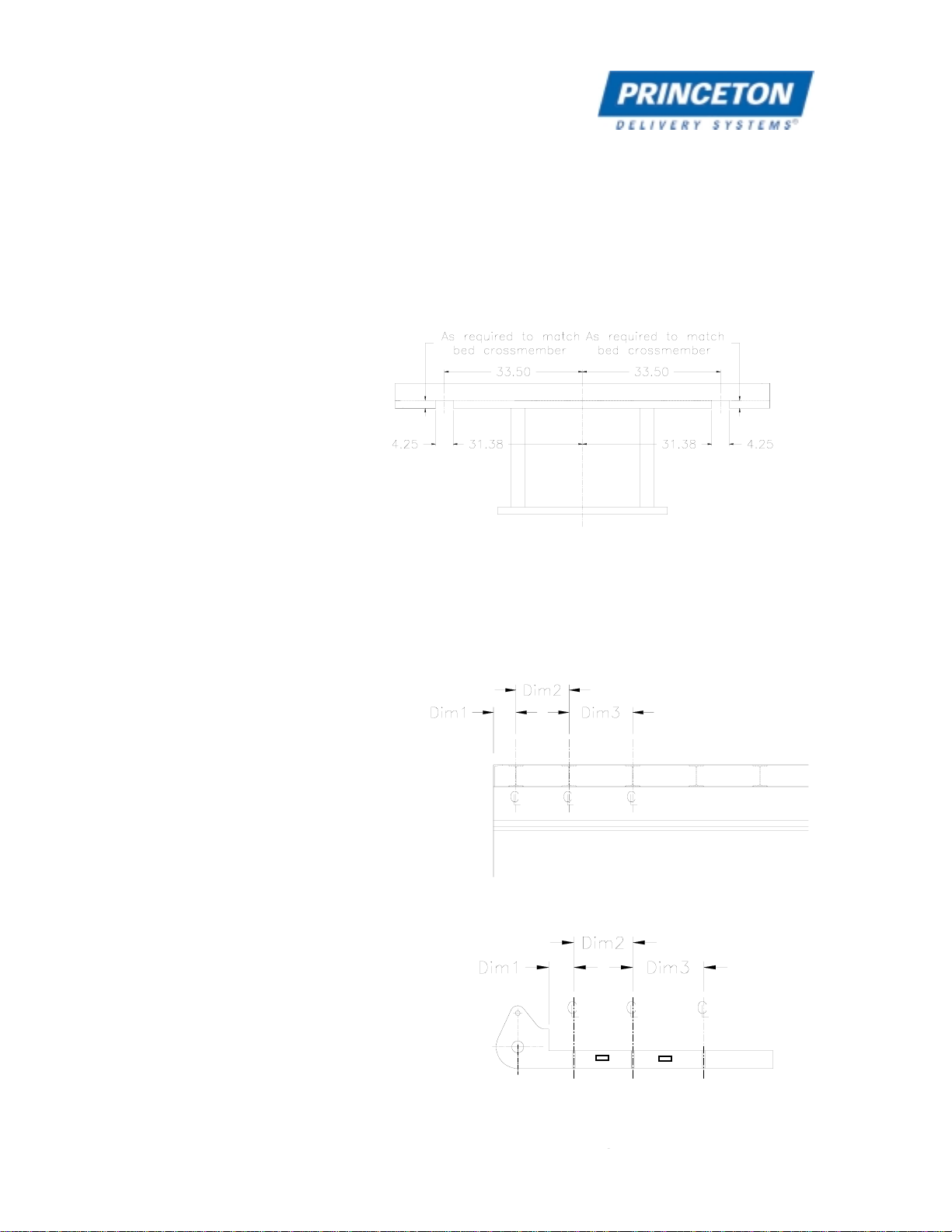
Main Installation
Hanger Plate
Installation Procedure Cut notches in c-channel at rear of bed as shown in Figure 3.
Clean weld area.
Measure centerlines of the truck or trailer bed crossmembers.
Install P90.292A (1/2 “ x 3” x 3”) Plates in the P90.1067C Hanger
Plate Weldments at each crossmember dimensional centerline as
shown in Figure 4 and Figure 5. Tack weld in place.
Figure 3
Figure 4
Figure 5

5
Main Installation (Cont.)
Hanger Plate
Installation Procedure Install Hanger Plate Assemblies (P90.1067C with P90.292A
Gussets) at 67” centerlines as shown in Figure 6 and Figure
7. Square the assemblies and clamp them in place.
Install the gussets connecting the Hanger Plate Assemblies and
the main c-channel as shown in Figure 8, and tack weld into place.
If gussets are too long, trim to fit. Do not move Cradle Plate
Assemblies.
Check to insure the Hanger Plate Assemblies are still square and
at 67” centerline.
Figure 6
Figure 7
Figure 8

5
Main Installation (Cont.)
Hanger Plate
Installation Procedure Weld Hanger Plate Assembly to the rear c-channel as shown.
Prepare the Bed Strengtheners for installation as shown in Figure
10 (right shown, left opposite). Chamfer the notch to allow the Bed
Strengtheners to fit over the Cradle Plate Assemblies. Also,
chamfer the strengtheners to allow them to be welded together.
Locate Bed Strengthener, clean notches, and tack weld into place.
Complete finish welding as shown in Figure 9 and Figure 11.
Install Shafts with Snap Rings in each Hanger Plate Assembly.
Install Hitch Pins.
Figure 9
Figure 10
Figure 11
6
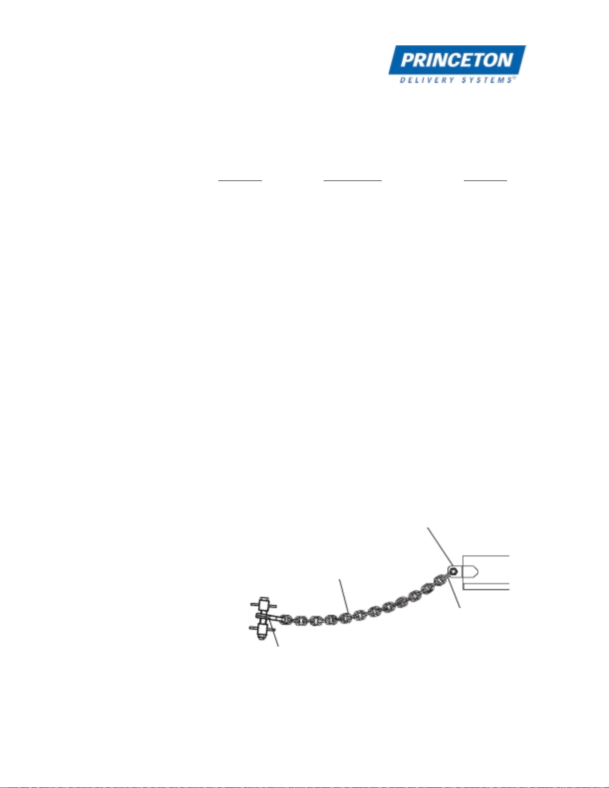
Safety Chains The safety chains are designed to provide a compact, easy to use
method of securing the PIGGY BACK®Delivery System.
Material Required Quantity Description Part No.
2 Chain Assembly P90.291B
2 Chain Loop P10.376C
One P90.291B consists of the following:
1 Chain 1/2" high test Gr. 43 606-108
working load rating 9,200 lb.
1 5/8" shackle w/ bolt and nut 606-106
working load rating 10,000 lb.
1 7/16" clevis slip hook w/ latch 606-107
working load rating 7,200 lb.
NOTE: Standard chains may NOT be substituted.
Installation Procedure Position the chain loops on the truck/trailer as shown in Figure 12.
Weld the chain loops securely to the truck/trailer.
Ensure that the Swing Latch Hook reaches the Mounting Bolt
when the PIGGY BACK®Delivery System is mounted.
Figure 12
Swing Latch Hook
Coupler
Chain
Chain Loop
PIGGY BACK®
Truck/Trailer

7
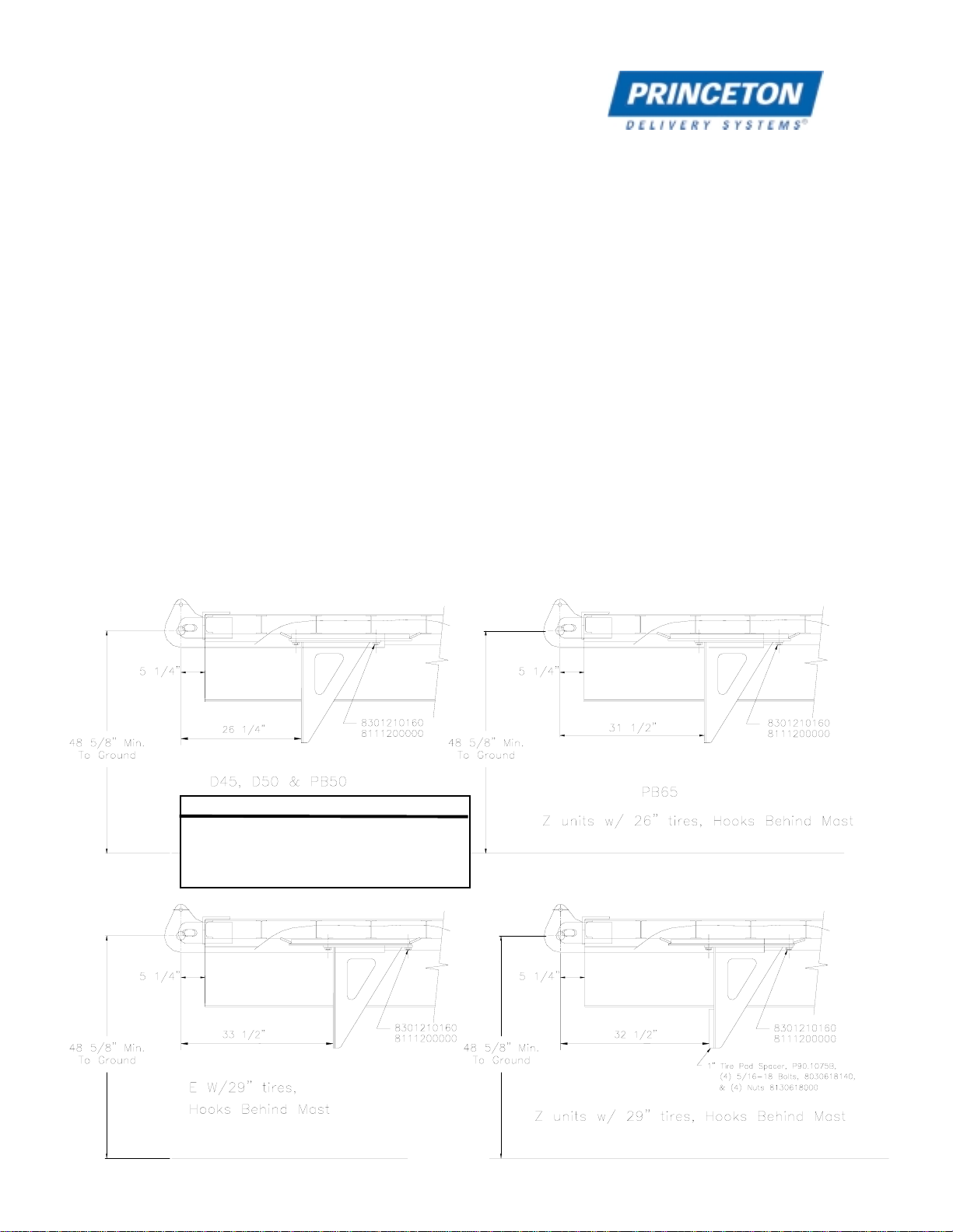
Front Tire Pads Front Tire Pads as shown in Figure 14 reduce the loading on the mast
structure and bearings. The pads should be installed so that they contact
evenly and on the centerline of the tires.
Material Required Part No. P90.1073 Kit contains the following:
Quantity Description Part No.
2 Upper Base Plate P90.1107B
1 Tire Pad Weldment, Left P90.971C
1 Tire Pad Weldment, Right P90.976C
8 Bolt, 3/4”-10 x 2” Long, Grade 8 8301210160
8 Lockwasher, 3/4” 8111200000
6 Gusset Plate P90.1074B
For Standard Models The horizontal distance from the center of the Cradle Plate Shaft to the
Tire Pad is 26 1/4" thru 33 1/2” (See Fig. 14). The vertical distance from
the center of the Cradle Plate Shaft to the Ground should be 48 5/8”
minimum.
IMPORTANT NOTE:
If the PIGGY BACK®has front tires other than 31" diameter, fork positioner attachment, or was pro-
duced for Home Depot, these dimensions may not be correct. Contact Princeton for information on
these applications.
Figure 13
Welding Base Plates P90.1107B
7
Front Tire Pads (Cont.)
Installation Install the Upper Base Plates (P90.1107B) by inserting the one inch tabs into the
Hanger Plate Weldment slots. Clamp and tack weld the Base Plates in position. Weld
inside of upper Base Plates to Crossmembers. To support the front edge of Base Plate
P90.1107B, use a Gusset Plate (P90.1074B). Weld one Gusset Plate to the end of the
Hanger plate as shown in Figure 13 to provide a surface to continue the weld on the
edge of the Base Plate. Also tack weld a Gusset Plate (P90.1074B) between the
Hanger Plate and the truck bed side member. Clamp and tack weld a Base Plate to
rear edge of base plate as shown in Figure 13. When setting Gusset Plates front and
rear, set the plates at an angle to Base Plate for increased strength. If material was
removed from the frame to weld the Upper Base Plate in place, replace material to
retain the beds structural integrity.
Install Tire Pad Weldments with 3/4”-10 x 2” Lg. Grade 8 Bolts and lockwashers. Refer
to Figure 14 for proper location of Tire Pad Weldments. If a PIGGY BACK®is available,
check tire pad placement by mounting the unit. Remove Tire Pads and finish welding
Base Plates.
Figure 14
NOTE:
The distance from the centerline of the mounting pin to face
of tire pad is critical! IF the dimension is greater than the
distances listed, the lifts will "sag" when the pressure is
released from the tilt. IF the lift's hooks will not reach the
mounting pins, check the transverse tubes.

8
Truck/Trailer 7-Pin Wiring Kit
Material Required Quantity Description Part No.
1 Truck/Trailer Receptacle Kit P80.07B
Installation To determine the location of the receptacle, mount the PIGGY BACK®to the
truck/trailer. Since the PIGGY BACK®receptacle is located in its left side, locate
receptacle to the left side of the truck/trailer. The coil plug provided with the PIGGY
BACK®is approximately 12 feet long at full extension for mounting location flexibility.
With the unit mounted, insert the coil plug into the receptacle on the left side.
Stretch the cable to the truck/trailer to determine a convenient and protected
location for the truck/trailer receptacle.
With the receptacle location determined, lay out the mounting holes.
Drill or torch out a 2" diameter through hole for the receptacle body.
Feed the receptacle harness through the hole and mark the location of the mounting
holes. Drill 2 holes, 3/16" diameter for self-tapping mounting screws. Secure the
receptacle to the truck/trailer with the screws.
Wiring - Trailer With the seven tap-in connectors provided, splice into the trailer wiring. In the package,
there will be six blue and one yellow wire taps. The yellow tap is for the white wire or
ground.
All wiring is required to be color coded to S.A.E. Standards. Use Table 1 to locate
the proper wire for trailers that have separate turn lamps & stop lamps.
If you have taken the unit off the trailer, reload to check electrical installation. Install
coil plug from your trailer to the receptacle on the left side of the forklift. The plug can
go in only one way to ensure proper alignment of wires.
Wiring - Truck With the seven tap-in connectors provided, splice into the truck wiring. In the package,
there will be six blue and one yellow wire taps. The yellow tap is for the white wire or
the ground.
All wiring is required to be color coded to S.A.E. Standards. Use Table 2 in to locate
the proper wire for trucks which have combined turn lamps & stop lamps.
To use both lights on each side of the PIGGY BACK®, cut the red wires to the out
side lamps and at the connector. On the left pair, install a jumper wire to connect to the
yellow wire on the inside lamp to the red wire on the outside lamp. On the right pair,
install a jumper wire to connect to the green wire on the inside lamp to the red wire on
the outside lamp.
8
Truck/Trailer 7-Pin Wiring Kit (cont.)
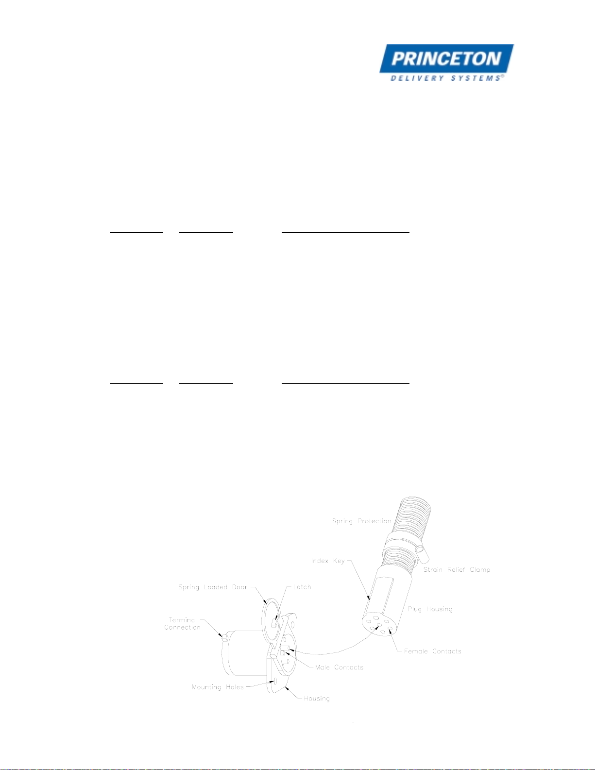
If you have taken the unit off the truck/trailer, reload to check electrical installation.
Install coil plug from your truck/trailer to the receptacle on the left side of the forklift.
The plug can go in only one way to insure proper alignment of the wires (Figure 15).
Table 1 - Wiring Circuits - Trailer with Separate Stop and Turn Lamps
Conductor Wire Color Lamp and Signal Circuits
Wht White Ground return to towing vehicle
Blk Black Clearance, side marker, and identification lamps
Yel Yellow Left-hand turn signal and hazard signal
Red Red Stop lamps and anti wheel lock devices
Grn Green Right-hand turn signal and hazard signal
Brn Brown Tail and license plate lamps
Blu Blue Back-up lamps
Table 2 - Wiring Circuits - Truck with Single Stop and Turn Lamps
Conductor Wire Color Lamp and Signal Circuits
Wht White Ground return to towing vehicle
Blk Black Clearance, side marker, and identification lamps
Yel Yellow Left-hand turn signal, hazard signal, and stop lamp.
Red - Not Used.
Grn Green Right-hand turn signal, hazard signal, and stop lamp.
Brn Brown Tail and license plate lamps
Blu Blue Back-up lamps
Figure 15
Table of contents
Other Princeton Forklift manuals

Popular Forklift manuals by other brands


Pegasolift
Pegasolift TPL 16-20-30 user manual

Presto Lifts
Presto Lifts PPS2200-62NFO-21 owner's manual

logitrans
logitrans Level Control LC4 manual

Engcon
Engcon GH1000L user manual

Presto Lifts
Presto Lifts Power Stak PPS2200-150AS Installation, operation and service manual

Doosan
Doosan D110S-5 with OCDB Specifications, Systems Operation, Disassembly & Assembly


