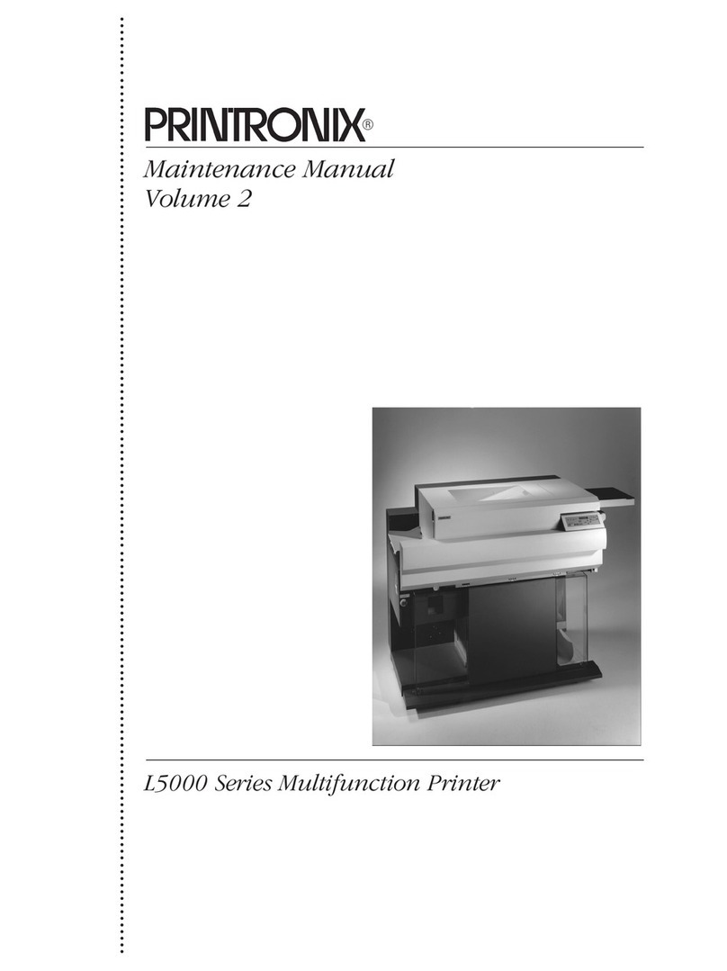
Printronix L5535 User manual

Maintenance Manual
Volume I of II
L5535 Multifunction Printer


Maintenance Manual
L5535 Multifunction Printer
Volume I of II

Trademark Acknowledgements
3M is a registered trademark of Minnesota Mining and Manufacturing
Company.
Postscript is a registered trademark of Adobe Systems, Inc.
Hitachi is a registered trademark of Kabushiki Kaisha Hitachi Seisakusho
DBA Hitachi, Ltd.
IBM is a registered trademark of International Business Machines
Corporation.
HP and PCL are registered trademarks of Hewlett-Packard Company.
Centronics is a registered trademark of Genicom Corporation.
Dataproducts is a registered trademark of Dataproducts Corporation.
Epson is a registered trademark of Seiko Epson Corporation.
DuraFusion, IGP, LaserLine, LinePrinter Plus, PGL, PrintNet, PSA, and
Printronix are registered trademarks, and Ribbon Minder is a trademark of
Printronix, Inc.
Magnum and QMS are registered trademarks, and Code V is a trademark of
Quality Micro Systems, Inc.
Microsoft, MS, MS-DOS, and Windows are registered trademarks of Microsoft
Corporation.
Toray is a registered trademark, and Toraysee is a trademark of Toray
Industries, Inc.
SELFOC is a registered trademark of Nippon Sheet Glass Co., Ltd.
PKUNZIP is a registered trademark of PKWARE, Inc.
This product uses Intellifont Scalable typefaces and Intellifont technology.
Intellifont is a registered trademark of Agfa Division, Miles Incorporated
(Agfa).
CG, Garth Graphic, Intellifont, and Type Director are registered trademarks,
and Shannon and CG Triumvirate are trademarks of Agfa Division, Miles
Incorporated (Agfa). CG Bodoni, CG Century Schoolbook, CG Goudy Old
Style, CG Melliza, Microstyle, CG Omega, and CG Palacio are products of
Agfa Corporation. CG Times, based on Times New Roman under license
from The Monotype Corporation Plc is a product of Agfa.
Univers is a registered trademark of Linotype AG and/or its subsidiaries.
Letraset is a registered trademark, and Aachen, Revue and University Roman
are trademarks of Esselte Pendaflex Corporation.
Futura is a registered trademark of Fundición Tipográfica Neufville, S.A.
ITC Avant Garde Gothic, ITC Benguiat, ITC Bookman, ITC Century, ITC
Cheltenham, ITC Clearface, ITC Galliard, ITC Korinna, ITC Lubalin Graph,
ITC Souvenir, ITC Tiepolo, ITC Zapf Chancery, and ITC Zapf Dingbats are
registered trademarks of International Typeface Corporation.
Albertus, Gill Sans, and Times New Roman are registered trademarks, and
Monotype Baskerville is a trademark of The Monotype Corporation Plc,
registered in the U.S. Pat. and TM office and elsewhere.

Hiroshige and Marigold are trademarks of AlphaOmega Typography, Inc.
Printronix, Inc. makes no representations or warranties of any kind regarding
this material, including, but not limited to, implied warranties of
merchantability and fitness for a particular purpose. Printronix, Inc. shall not
be held responsible for errors contained herein or any omissions from this
material or for any damages, whether direct, indirect, incidental or
consequential, in connection with the furnishing, distribution, performance or
use of this material. The information in this manual is subject to change
without notice.
This document contains proprietary information protected by copyright. No
part of this document may be reproduced, copied, translated or incorporated
in any other material in any form or by any means, whether manual, graphic,
electronic, mechanical or otherwise, without the prior written consent of
Printronix, Inc.
Copyright
1998, 2004, Printronix, Inc. All rights reserved.


1 Introduction ...................................................... I–19
About This Manual............................................................................ I–19
How To Locate Information ........................................................ I–19
Safety Notices And Special Information ..................................... I–19
Switches And Display Messages ............................................... I–20
Related Documents.................................................................... I–20
General Safety Precautions.............................................................. I–20
Setup Safety Precautions ................................................................. I–22
Printer......................................................................................... I–22
Safety Label Locations And Printer Views........................................ I–23
Printer Features ................................................................................ I–28
Tools, Test Equipment, And Supplies............................................... I–29
2 Setup................................................................ I–31
Power Requirements ........................................................................ I–31
Site Selection.................................................................................... I–32
Unpacking And Leveling ................................................................... I–35
Cable Connections ........................................................................... I–37
Power Cord ................................................................................ I–37
Interface Cable ........................................................................... I–40
Installing The First Photoreceptor Drum ........................................... I–41
Adding The Developer ...................................................................... I–47
Installing The Developing Unit .......................................................... I–49
Installing The Toner Cartridge And Waste Toner Bottle ................... I–52
Loading Fanfold Paper ..................................................................... I–55
Loading Cut Sheet Paper ................................................................. I–57
Setting Cassette Paper Size (Optional Procedure) .......................... I–59
Setting The Power Supply Voltage ................................................... I–60
3 Scheduled Maintenance .................................. I–67
Maintaining Print Quality................................................................... I–67
Service Level Page Counts .............................................................. I–68
Clearing Service Level Messages.............................................. I–69
About Page Counter Software ................................................... I–69
Volume I
Table of Contents

Table of Contents
Maintenance Schedules ................................................................... I–69
User’s Cleaning Schedule.......................................................... I–69
User’s Replacement Schedule................................................... I–70
Tech Service Replacement Schedule ........................................ I–71
Maintenance Kits .............................................................................. I–72
General Cleaning.............................................................................. I–76
Cleaning The Chargers..................................................................... I–82
Cleaning The Fuser Unit Cover Glass And Lamp Filter.................... I–86
Cleaning The Cut Sheet Option Rollers............................................ I–89
Major Cleaning.................................................................................. I–93
Cleaning The Flash Power Supply Filter .......................................... I–99
4 Troubleshooting ............................................. I–101
Overview......................................................................................... I–101
Jam Detection Sensors ............................................................ I–101
System Block Diagram ................................................................... I–102
Hidden Control Menus .................................................................... I–103
Global Memory Adjust Menu .................................................... I–104
Printer Control Menu ................................................................ I–105
Fanfold Paper Jams........................................................................ I–107
Paper Jam Near The Tractor ................................................... I–107
Paper Jam Near The Paper Output Section ............................ I–108
Cut Sheet Paper Jams.................................................................... I–111
Paper Jam At The Back Of The Paper Cassette ..................... I–111
Paper Jam In The Transport Input Section .............................. I–112
Paper Jam In The Transport Output Section ........................... I–114
Paper Jam In The Face Up Or Face Down Paper Path........... I–115
Status Messages And Error Messages .......................................... I–116
Error Message Table................................................................ I–116
Error Message Troubleshooting Procedures ........................... I–128
Error Code 01 — Front Cover Open ........................................ I–128
Error Code 02 — Fan-fold Paper Empty: Upon Power-on ....... I–130
Error Code 02 — Fan-fold Paper Empty: When
Loading/Beginning Print ........................................................... I–131
Error Code 03 — Paper Jam at Fuser (C) ............................... I–131
Error Code 04 — Paper Jam at Exit (D) (transport section)..... I–132
Error Code 05 — Paper Jam at Exit (D)
(paper output section) .............................................................. I–133
Error Code 07 — Scuff Lever Open (knob "C")........................ I–134
Error Code 08 — Cut-sheet Path Open ................................... I–134
Error Code 09 — Transport Motor Fail (complete stop) ........... I–135
Error Code 0A — Cutter Fail (front) ......................................... I–136

Table of Contents
Error Code 0B — Cutter Fail (rear) .......................................... I–136
Error Code 0C — Transfer Platform Fail (upper) ..................... I–138
Error Code 0D — Transfer Platform Fail (lower) ...................... I–138
Error Code 11 — Paper Jam at Drum (B) ................................ I–140
Error Code 12 — Paper Jam at Fuser (C)................................ I–140
Error Code 13 — Paper Jam at Exit (D): Straight Output
(faceup) .................................................................................... I–141
Error Code 13 — Paper Jam at Exit (D) (Cut-sheet
Facedown Output).................................................................... I–141
Error Code 14 — Tractor Speed Too High............................... I–142
Error Code 15 — Tractor Speed Too Low................................ I–142
Error Code 16 — Paper Jam at Entrance (A)........................... I–144
Error Code 17 — High Voltage Fail.......................................... I–144
Error Code 18 — Drum Motor Fail (complete stop).................. I–146
Error Code 19 — Surface Voltage Too High............................ I–147
Error Code 1A — Surface Voltage Too Low ............................ I–149
Error Code 1B — Tractor Detent Fail....................................... I–150
Error Code 1E — Fuser Supply Fail......................................... I–151
Error Code 1F — Fuser Failure................................................ I–151
Error Code 20 — Fuser Lamp Overheat .................................. I–152
Error Code 26 — No Cleaning Unit .......................................... I–153
Error Code 28 — Waste Toner Full.......................................... I–153
Error Code 29 — No Waste Toner Box.................................... I–154
Error Code 2A — Toner Low.................................................... I–154
Error Code 2D — Toner Empty ................................................ I–154
Error Code 2B — Toner Density Too High............................... I–155
Error Code 2C — Toner Density Too Low ............................... I–155
Error Code 32 — LED Head Overheat..................................... I–155
Error Codes 38 through 47 — MC Board CPU Internal Error .. I–156
Error Codes 48 through 4D — Controller Comm. Fail.............. I–156
Error Codes 50 through 53 and 5B — Stacker Fail.................. I–157
Error Code 5D — Stacker Comm. Fail ..................................... I–157
Error Code 54 — Stacker Interlock Fail.................................... I–158
Error Code 55 — Stacker Fail .................................................. I–158
Error Code 56 — Stacker Full .................................................. I–159
Error Code 57 — Stacker Not Ready ....................................... I–159
Error Code 58 — Stacker Not Auto Mode ................................ I–159
Error Code 59 — Stacker Fail .................................................. I–160
Error Code 5A — Stacker Fail.................................................. I–161
Error Code 5C — Stacker Fail.................................................. I–162
Error Codes 60 through 62, 6E, and 70 — Cut-sheet
Comm. Fail ............................................................................... I–162

Table of Contents
Error Code 63 — Cut-sheet Feeder Fail .................................. I–162
Error Code 64 — Cut-sheet Paper Skew ................................. I–163
Error Code 65 — Cut-sheet Pick Miss ..................................... I–163
Error Code 66 — No Paper Cassette....................................... I–164
Error Codes 67, 69, and 6B — Paper Jam at Entrance (A) ..... I–164
Error Codes 68 and 6A — Paper Jam at Entrance (A) ............ I–165
Error Code 6C — Cut-sheet Cover Open ................................ I–165
Error Code 6D — Cut-sheet Motor Fail.................................... I–166
Error Code 6F — Cut-sheet Paper Empty ............................... I–167
Error Code 78 — Main Charger High Voltage Error................. I–167
Error Code 79 — Transfer Charger High Voltage Error ........... I–168
Error Code 7A — Precharger High Voltage Error .................... I–168
Error Code 7B — Cleaning Bias High Voltage Error ................ I–169
Error Code 7C — Developing Bias High Voltage Error............ I–170
Error Code 7D — Separator Charger High Voltage Error ........ I–170
Troubleshooting Other Symptoms .................................................. I–171
Smell Of Toner ......................................................................... I–172
Broken Fuser Unit Cover Glass ............................................... I–173
Incomplete Fusing .................................................................... I–174
Paper Jam ................................................................................ I–177
Print Quality.............................................................................. I–179
Transfer (Elevator) Motor Abnormal Error................................ I–184
Abnormal Noises ...................................................................... I–184
Developer Overflows ................................................................ I–184
Toner Is Discharged................................................................. I–185
Power Stacker.......................................................................... I–185
5 Adjustment Procedures.................................. I–189
MC Board Adjustments................................................................... I–189
MC Board Switches.................................................................. I–191
MC Board Test Points .............................................................. I–195
MC Board Variable Resistors................................................... I–200
MC Board LEDs ....................................................................... I–202
MC Board Fuses ...................................................................... I–204
Setting NVRAM Values ............................................................ I–206
Adjusting Feed Motor Speed.................................................... I–207
Adjusting Drum Motor Speed ................................................... I–207
Adjusting Tractor Motor Gain ................................................... I–207
Adjusting Eraser Lamp Voltage................................................ I–208
Adjusting Toner Density Sensor............................................... I–208
Confirming MC Board Operation .................................................... I–210
Confirming the Developing Bias Voltage Control Circuit .......... I–210

Table of Contents
Confirming The Main Charger Current Control Circuit ............. I–211
Confirming The Sleeve Motor Operation.................................. I–212
Confirming The Magroll Motor Operation ................................. I–212
Confirming The Toner Supply Clutch Operation ...................... I–212
Confirming The Head Cooling Fan Operation .......................... I–212
Confirming The Head Blower Fan Operation ........................... I–212
Confirming The Vacuum Fan Operation................................... I–212
Confirming The Preheat Lamp Operation ................................ I–213
Confirming The Drum Counter Operation ................................ I–213
Confirming The Drum Surface Potential Sensor Operation ..... I–213
Other Print Engine Adjustments ..................................................... I–215
Adjusting The Drum Surface Potential Sensor......................... I–215
Adjusting The Tractors ............................................................. I–215
Adjusting The Top of Form....................................................... I–219
DC Power Supply Board Adjustments ............................................ I–223
DC Power Supply Board Switches ........................................... I–223
DC Power Supply Board Variable Resistors ............................ I–223
DC Power Supply Board Fuses................................................ I–225
Flash Power Supply Adjustments ................................................... I–227
Loading Flash Memory ................................................................... I–228
The lasr2fls Utility Program ...................................................... I–228
Downloading Into Flash Memory.............................................. I–231
6 Replacement Procedures .............................. I–237
Overview......................................................................................... I–237
Front Cover .............................................................................. I–238
Left Rear Cover........................................................................ I–239
Right Rear Cover ..................................................................... I–240
Top Cover ................................................................................ I–243
Stand Cover ............................................................................. I–246
Inside The Front Cover ................................................................... I–247
Waste Toner Recovery Unit ..................................................... I–248
Developing Unit........................................................................ I–252
Toner Cartridge ........................................................................ I–252
Photoreceptor Drum ................................................................. I–253
Proper Disposal Of A Drum Unit .............................................. I–259
Drum Peripheral Equipment ..................................................... I–260
Fuser Unit................................................................................. I–266
Transfer Assembly ................................................................... I–271
Inside The Rear Cover.................................................................... I–280
MC Board ................................................................................. I–281
DC Power Supply Board .......................................................... I–282

Table of Contents
Motors ...................................................................................... I–284
Fans ......................................................................................... I–297
Solenoids ................................................................................. I–301
Miscellaneous .......................................................................... I–303
Under The Top Cover ..................................................................... I–314
LED Print Head ........................................................................ I–315
High-Voltage (Corona) Power Supply ...................................... I–319
Cutter Unit ................................................................................ I–320
Sensors And Switches ............................................................. I–323
Gates........................................................................................ I–331
Behind The Stand Cover ................................................................ I–332
Smoke Filter ............................................................................. I–332
Flash Power Supply ................................................................. I–333
Capacitor.................................................................................. I–340
Other............................................................................................... I–344
Tractor Removal....................................................................... I–344
Paper Back-Feed Sensor (PBFS) (Top Of Form Sensor) ........ I–346
Paper Near-End Sensor (PNES).............................................. I–347
Control Panel ........................................................................... I–349
Controller Module ........................................................................... I–350
Controller Board ....................................................................... I–350
Terminating Resistors .............................................................. I–354
Power Supply (In Controller Module) ....................................... I–356
Cooling Fan .............................................................................. I–358

7 Illustrated Parts Breakdown ............................ II–19
Overview.......................................................................................... II–19
Illustrated Parts Breakdown............................................................. II–20
8 Principles of Operation.................................. II–111
Printing System Descriptions......................................................... II–111
General ................................................................................... II–111
The Printing Process............................................................... II–111
How Images Are Processed .......................................................... II–112
Bit Mapping ............................................................................. II–112
Job Recovery .......................................................................... II–112
The Printing Mechanisms .............................................................. II–113
Photoconductive Section ............................................................... II–114
Discharge ................................................................................ II–114
Main Charging ......................................................................... II–114
Exposure ................................................................................. II–116
Developing Section........................................................................ II–117
Developing Unit....................................................................... II–117
Principles Of Developing ......................................................... II–118
Image Transfer/Separation Section ............................................... II–120
Transfer ................................................................................... II–120
Separation ............................................................................... II–120
Fixing Section (Fuser Unit) ............................................................ II–122
Preheating ............................................................................... II–122
Flash Fusing............................................................................ II–122
Cleaning Section............................................................................ II–123
Precharging (Precleaning Charging) ....................................... II–123
Drum Cleaning ........................................................................ II–123
Paper Feed, Transport, And Output Sections................................ II–124
Paper Detection ...................................................................... II–124
Paper Loading ......................................................................... II–126
Paper Transport ...................................................................... II–128
Paper Output........................................................................... II–129
Paper Parking ......................................................................... II–130
Volume II
Table of Contents

Table of Contents
Drive System Descriptions............................................................. II–132
Drum Drive .............................................................................. II–133
Developing Roller Drive .......................................................... II–134
Main Unit Feed Roller Drive .................................................... II–135
Gate Drive ............................................................................... II–136
Transfer Unit Drive .................................................................. II–137
Tractor Drive ........................................................................... II–137
Perforation Cutter Drive .......................................................... II–138
Separator Claw Drive .............................................................. II–139
Cut Sheet Paper Feed Section Drive ...................................... II–140
Control System Descriptions ......................................................... II–141
Paper Transport System Monitoring ....................................... II–142
Motor Rotation Control ............................................................ II–145
Drum Surface Potential Control .............................................. II–151
Toner Density Control ............................................................. II–152
Remaining Toner Level Monitoring ......................................... II–154
Waste Toner Monitoring.......................................................... II–155
Head Temperature Monitoring ................................................ II–156
Fuser Temperature Monitoring................................................ II–157
Developing Bias Adjustment ................................................... II–158
Operational Sequences ................................................................. II–159
Electronics Initialization ........................................................... II–160
Mechanical Initialization .......................................................... II–161
Printing Operations ................................................................. II–162
Command Operations ............................................................. II–167
A Electrical and Wire Data................................ II–171
Block Diagram ............................................................................... II–171
Printer Interconnection Diagram .................................................... II–172
Print Engine Interconnection Diagram ........................................... II–173
Acronyms For Print Engine Interconnection Diagram.................... II–176
Explanation Of Circuits According To Function ............................. II–179
Drum Surface Potential Control Circuit ................................... II–179
Developing Bias Control Circuit .............................................. II–181
Toner Density And Toner Empty Circuits ................................ II–183
Drum Motor Control Circuit ..................................................... II–185
Drum Counter Circuit .............................................................. II–186
Tractor Motor Control Circuit................................................... II–187
Main Unit Feed Motor Control Circuit...................................... II–190
Transfer Elevator Motor Control Circuit................................... II–191
Cutter Motor Control Circuit .................................................... II–193

Table of Contents
Input / Output Signals .................................................................... II–194
LVX040 Controller Board Input/Output Signals....................... II–194
MC Board (MC-PCBA) Input/Output Signals........................... II–203
DC Power Supply Board (PS-PCBA) Input/Output Signals..... II–216
Unit Interface ................................................................................. II–221
LED Array................................................................................ II–221
Flash Power Supply ................................................................ II–225
Developing Unit....................................................................... II–228
High-Voltage (Corona) Power Supply ..................................... II–231
B Optional Cut Sheet Feeder ........................... II–235
Physical Description ...................................................................... II–235
Front Side................................................................................ II–235
Back Side ................................................................................ II–236
Rear Side (Board Side) ........................................................... II–237
Paper Feed Cassette..................................................................... II–238
Setup And Connections ................................................................. II–239
Setup....................................................................................... II–239
Connections ............................................................................ II–241
Basic Principles ............................................................................. II–242
Drive Principles ....................................................................... II–243
Cassette Principles ................................................................. II–243
Control Principles........................................................................... II–244
Upper Level / Lower Level Paper Size Sensor........................ II–244
Paper Feed Cassettes ............................................................ II–245
Upper Level / Lower Level Paper Empty Sensor
(PES1 / PES2) ........................................................................ II–246
Cut Sheet Feed Sensor (PFS),
Paper Register Sensor (PRS) ................................................. II–246
Paper Timing Sensor (PTS) .................................................... II–247
Cut Sheet Pickup Motor Encoder (PME)................................. II–248
Cut Sheet Feed Motor Encoder (FME).................................... II–249
Paper Guide Interlock Switch (ICIL) ........................................ II–250
Detection Errors............................................................................. II–251
Upper Level Cassette Section Error........................................ II–251
Lower Level Cassette Section Error........................................ II–251
Transfer Unit Error................................................................... II–252
Unit Sequencer Section Errors................................................ II–253
Basic Operation ............................................................................. II–254
Mechanism Initialization .......................................................... II–255
Analog Input Processing ......................................................... II–255
Chattering Absorption Processing........................................... II–255

Table of Contents
Status Confirmation Processing.............................................. II–255
Confirmation Processing Of Unit Of Error Occurrence ........... II–255
Communication Processing .................................................... II–255
Driving Actuators ..................................................................... II–255
Cut Sheet Output Unit.................................................................... II–256
Physical Description ................................................................ II–256
Setup and Connections........................................................... II–258
Basic Principles ....................................................................... II–261
C Optional Power Paper Stacker...................... II–263
Physical Description ...................................................................... II–263
Front (Output Side) ................................................................. II–263
Rear (Input Side)..................................................................... II–264
Front (Interior) ......................................................................... II–265
Setup And Connections ................................................................. II–266
Setup....................................................................................... II–266
Connections ............................................................................ II–269
Removal......................................................................................... II–270
Operation ....................................................................................... II–271
Sensors And Actuators .................................................................. II–274
Drive Principles.............................................................................. II–275
Feed Roller And Transfer Belt................................................. II–275
Swinger ................................................................................... II–277
Assisting Arms ........................................................................ II–278
Elevator Table ......................................................................... II–279
Control Principles........................................................................... II–280
Transfer Unit Paper Sensor (Paper Moving Sensor) (PMS) ... II–280
Jam Sensor (PPS) .................................................................. II–281
Paper Surface Sensor 1 (PSS1),
Paper Surface Sensor 2 (PSS2) ............................................. II–282
Stacker Full Sensor (SFS), Elevator Down Sensor (EDS) ...... II–283
Stacker Motor Encoder (SME),
Elevator Motor Encoder (EME) ............................................... II–284
Swinger Position Sensor (SPS),
Assisting Arm Position Sensor (APS1) ................................... II–285
Elevator Upper Limit Switch (LIMT1),
Elevator Lower Limit Switch (LIMT2) ...................................... II–286
Safety Sensor 1 (SS1), Safety Sensor 2 (SS2)....................... II–287
Elevator Keys (ESWA / ESWS / ESWD / ESWH)................... II–287
Detection Errors............................................................................. II–288
Operator Call Status Errors..................................................... II–288
Service Call Status Errors ....................................................... II–288

Table of Contents
Basic Operation ............................................................................. II–289
Status Confirmation Processing .............................................. II–290
Communication Processing..................................................... II–290
Driving The Stacker................................................................. II–290
Driving The Elevator Motor...................................................... II–290
Driving The Swinger Motor...................................................... II–290
Driving The Assisting Arm Drive Motor ................................... II–290
Switch Monitoring.................................................................... II–290
Belt Removal Procedures .............................................................. II–291
Power Stacker Cover .............................................................. II–292
Inside The Left Frame ............................................................. II–293
Inside The Right Frame........................................................... II–299
Swinger Belts .......................................................................... II–303
Elevator Belt............................................................................ II–310
Stacker Motor.......................................................................... II–315
D Engine Checker ............................................ II–319
Overview........................................................................................ II–319
Connecting The Engine Checker................................................... II–320
Disconnecting The Engine Checker .............................................. II–323
Using The Control Panel................................................................ II–323
Operation ................................................................................ II–324
Basic Menu .................................................................................... II–325
Device Check Menu....................................................................... II–326
Selecting A Mode/Item/Device ................................................ II–334
Reading Device Status (Input Device Check) ......................... II–335
Driving/Stopping A Device (Output Device Check) ................. II–335
Volume Adjustment Menu.............................................................. II–337
Surface Potential..................................................................... II–338
Eraser Lamp............................................................................ II–338
Drum Motor ............................................................................. II–338
Feed Motor .............................................................................. II–339
Tractor Motor........................................................................... II–339
Toner Density.......................................................................... II–339
Basic Operation Menu ................................................................... II–340
Fanfold Paper.......................................................................... II–340
Cut Sheet Paper...................................................................... II–341
Memory Operation Menu ............................................................... II–342
Reading And Changing Data .................................................. II–343

Table of Contents

I–19
1Introduction
About This Manual
This manual explains how to maintain and repair the L5535 printer at the field
service level of maintenance. It covers alignments and adjustments,
preventive and corrective maintenance, basic troubleshooting, and principles
of operation.
This manual does not explain how to configure or operate the printer. That
information is in the
User’s Manual,
which supplements this manual.
How To Locate Information
This manual consists of two volumes which are designed so that you can find
the information you need to maintain and repair the printer. You can locate
maintenance information in two ways:
•Use the Table of Contents at the front of Volume 1 and Volume 2.
•Use the Index at the end of Volume 1 and Volume 2.
Read the entire procedure before beginning any maintenance task. Gather all
required tools and make sure you understand all warnings, cautions, and
notes before you begin working on the printer.
Safety Notices And Special Information
For your safety and to protect valuable equipment, it is very important that you
read and comply with all information highlighted under the following special
headings: WARNING, CAUTION, IMPORTANT, and NOTE. Safety notices
which include conditions that could harm you are written in English and
German. (See also the safety topics in English and German that follow this
topic.)
WARNING
A warning notice calls attention to a condition that could harm you or
damage the printer.
CAUTION
A caution notice calls attention to a condition that could damage the
printer.
IMPORTANT
An important notice provides information that is vital to proper
operation of the printer.
NOTE: A note provides information concerning printer maintenance
considered important enough to emphasize.

I–20
Chapter 1 General Safety Precautions
Switches And Display Messages
In this manual, switches and indicators that are labeled on the printer appear
in uppercase letters.
Control panel display messages also appear in uppercase letters.
Example: “Press the CLEAR switch to take the printer to the OFFLINE
READY state.”
Related Documents
For additional information about printer configuration and operation, and
optional interfaces, refer to the following documents:
•
L5535 Multifunction Printer User’s Manual
(P/N 171516-001)
•
LinePrinter Plus®Emulation for LaserLine®Printers Programmer’s
Reference Manual
(P/N 705867-001)
•
IGP®/PGL®Emulation for LaserLine®Printers Programmer’s Reference
Manual
(P/N 702610-001)
•
IGP®/VGL Emulation for LaserLine®Printers Programmer’s
Reference Manual
(P/N 148802-001)
General Safety Precautions
This section provides safety information for technicians who are installing and
maintaining L5535 printers.
Installation, initial setup, testing and
maintenance should be performed only by a factory-trained service
representative.
WARNING
The printer relies on protective devices in the building installation for
protection. The printer must be connected to a 30 Amp, 200, 220, or 240
VAC outlet.
The operator-accessible power switch does not shut off all power to the
printer.
You must unplug the power cord to shut off all power to the printer.
VORSICHT
Der Drucker nutzt die elektrischen Schutzeinrichtungen der
Gebäudeinstallation. Der Drucker muß an einen mit 30 A abgesicherten
Stromkreis mit 200, 220 oder 240 V Wechselspannung angeschlossen
werden.
Der für den Bediener zugängliche Netzschalter macht den Drucker nicht
vollständig stromlos. Ziehen Sie das Netzkabel heraus, um die
Stromzufuhr zum Drucker vollständig zu unterbrechen.
WARNING
Be aware of components in the printer that are potentially hazardous or
easily damaged. For example, the fuser unit becomes very hot under
normal operating conditions, and several components use high voltage.
Other manuals for L5535
3
Table of contents
Other Printronix All In One Printer manuals
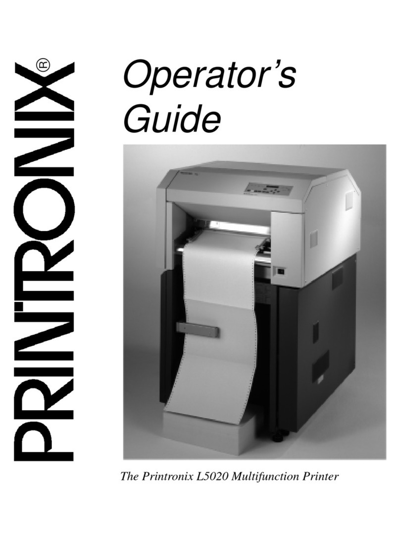
Printronix
Printronix L5020 Manual

Printronix
Printronix L5020 User manual

Printronix
Printronix P9012 User manual

Printronix
Printronix P3000 Series Assembly instructions
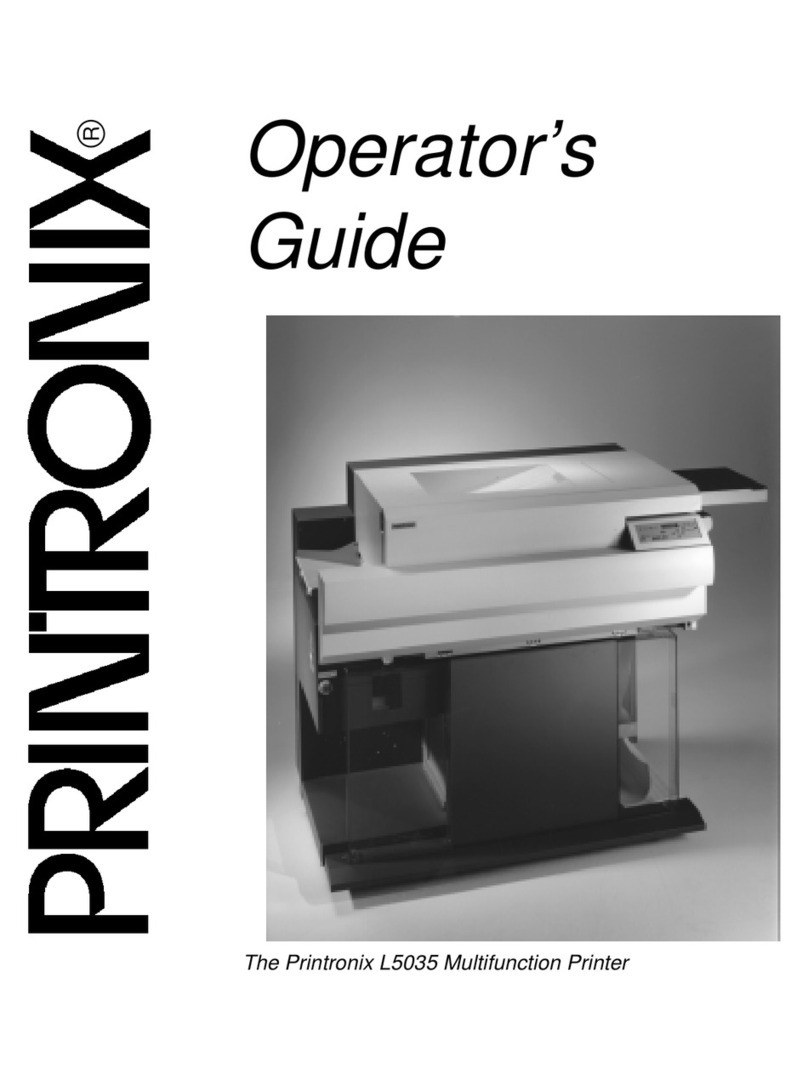
Printronix
Printronix L5035 Manual
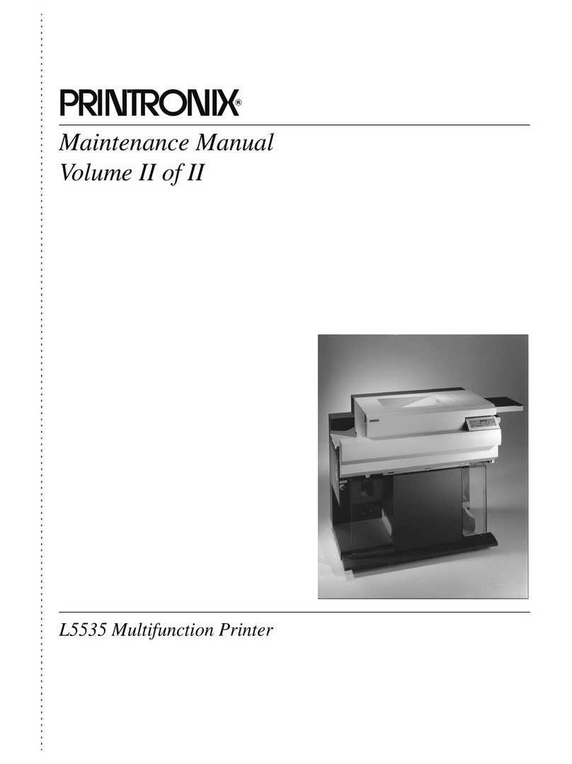
Printronix
Printronix L5535 User manual

Printronix
Printronix P9000 Series Assembly instructions

Printronix
Printronix L5535 User manual

Printronix
Printronix L5020 User manual

Printronix
Printronix L5535 Manual

