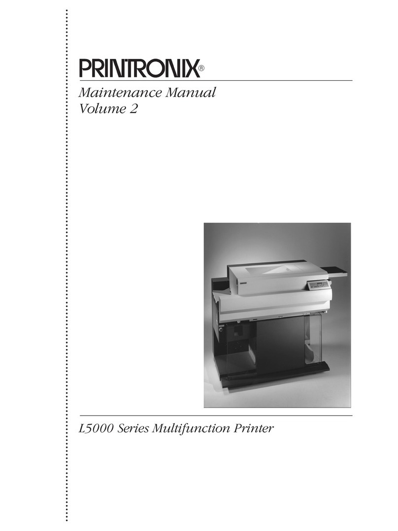
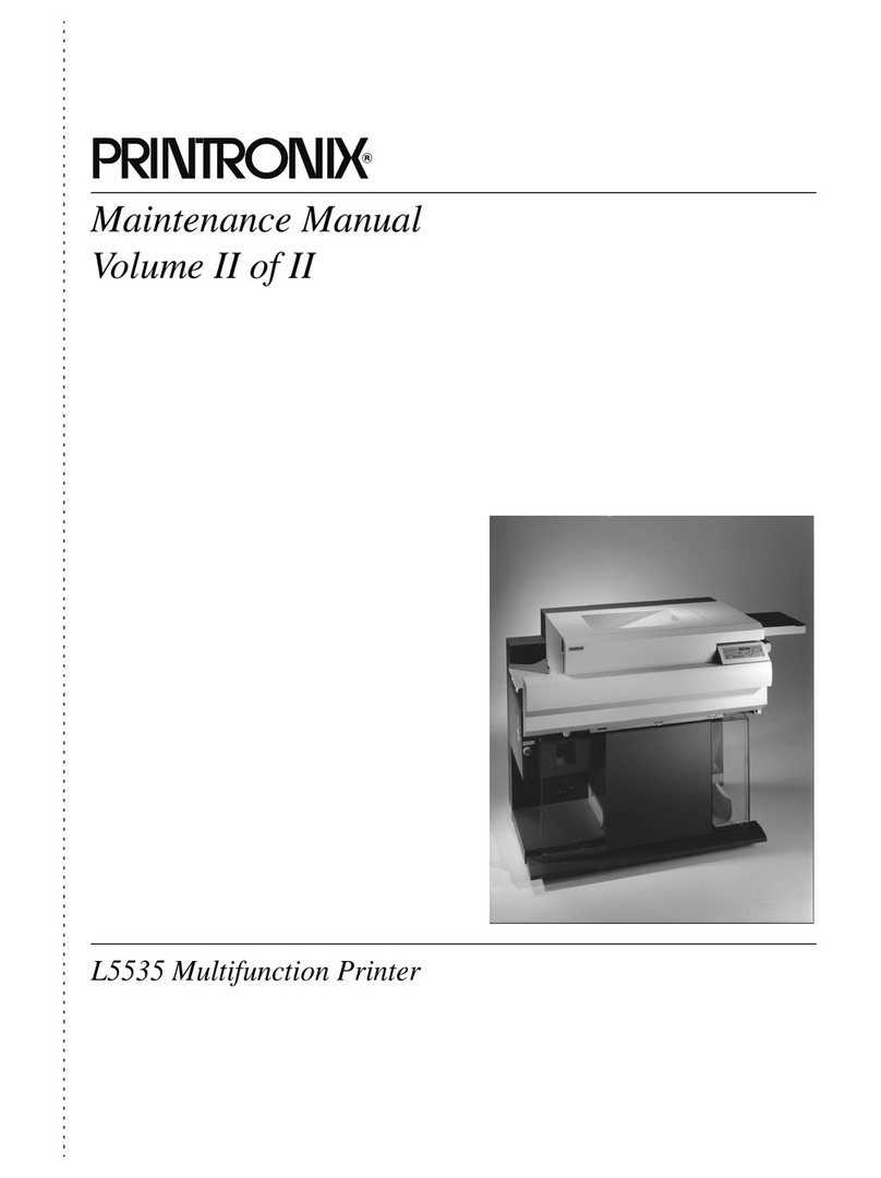
Printronix L5035 User manual

Maintenance Manual
Volume 2
®
L5035 Multifunction Printer


705648-001C
Maintenance Manual
L5035 Multifunction Printer
®
Volume 2

Trademark Acknowledgements
Postscript is a registered trademark of Adobe Systems, Inc.
IBM is a registered trademark of International Business Machines
Corporation.
HP and PCL are registered trademarks of Hewlett-Packard Company.
Centronics is a registered trademark of Genicom Corporation.
Dataproducts is a registered trademark of Dataproducts Corporation.
Epson is a registered trademark of Seiko Epson Corporation.
DuraFusion, IGP, LaserLine, LinePrinter Plus, PGL, PSA, and Printronix are
registered trademarks, and Ribbon Minder is a trademark of Printronix, Inc.
Magnum and QMS are registered trademarks, and Code V is a trademark of
Quality Micro Systems, Inc.
Microsoft, MS, MS-DOS, and Windows are registered trademarks of Microsoft
Corporation.
This product uses Intellifont Scalable typefaces and Intellifont technology.
Intellifont is a registered trademark of Agfa Division, Miles Incorporated
(Agfa).
CG, Garth Graphic, Intellifont, and Type Director are registered trademarks,
and Shannon and CG Triumvirate are trademarks of Agfa Division, Miles
Incorporated (Agfa). CG Bodoni, CG Century Schoolbook, CG Goudy Old
Style, CG Melliza, Microstyle, CG Omega, and CG Palacio are products of
Agfa Corporation. CG Times, based on Times New Roman under license
from The Monotype Corporation Plc is a product of Agfa.
Univers is a registered trademark of Linotype AG and/or its subsidiaries.
Letraset is a registered trademark, and Aachen, Revue and University Roman
are trademarks of Esselte Pendaflex Corporation.
Futura is a registered trademark of Fundición Tipográfica Neufville, S.A.
ITC Avant Garde Gothic, ITC Benguiat, ITC Bookman, ITC Century, ITC
Cheltenham, ITC Clearface, ITC Galliard, ITC Korinna, ITC Lubalin Graph,
ITC Souvenir, ITC Tiepolo, ITC Zapf Chancery, and ITC Zapf Dingbats are
registered trademarks of International Typeface Corporation.
Albertus, Gill Sans, and Times New Roman are registered trademarks, and
Monotype Baskerville is a trademark of The Monotype Corporation Plc,
registered in the U.S. Pat. and TM office and elsewhere.
Hiroshige and Marigold are trademarks of AlphaOmega Typography, Inc.
Printronix, Inc. makes no representations or warranties of any kind regarding
this material, including, but not limited to, implied warranties of
merchantability and fitness for a particular purpose. Printronix, Inc. shall not
be held responsible for errors contained herein or any omissions from this
material or for any damages, whether direct, indirect, incidental or
consequential, in connection with the furnishing, distribution, performance or
use of this material. The information in this manual is subject to change
without notice.

This document contains proprietary information protected by copyright. No
part of this document may be reproduced, copied, translated or incorporated
in any other material in any form or by any means, whether manual, graphic,
electronic, mechanical or otherwise, without the prior written consent of
Printronix, Inc.
Copyright 1998, 2001, Printronix, Inc. All rights reserved.


Volume 1
Table of Contents
1 Introduction........................................................ 21
About This Manual............................................................................21
How to Locate Information .........................................................21
Safety Notices and Special Information .....................................21
Switches and Display Messages................................................22
Related Documents....................................................................22
General Safety Precautions..............................................................23
Setup Safety Precautions.................................................................25
Printer.........................................................................................25
Consumables .............................................................................25
Safety Label Locations and Printer Views.......................................26
Allgemeine Sicherheitsvorkehrungen...............................................30
Sicherheitsvorkehrungen bei der ersten Inbetriebnahme.................32
Drucker.......................................................................................32
Verbrauchsmaterial....................................................................32
Befestigungsorte der Sicherheitsetiketten und Druckeransichten..33
Printer Features................................................................................37
Tools, Test Equipment, and Supplies...............................................38
2 Setup................................................................. 41
Power Requirements........................................................................41
Site Selection....................................................................................42
Unpacking and Leveling ...................................................................45
Cable Connections ...........................................................................47
Power Cord ................................................................................ 47
Interface Cable...........................................................................50
Consumables Installation..................................................................52
3 Installing Consumables ..................................... 53
Installing the First Photoreceptor Drum ............................................53
Adding the Developer.......................................................................59
Installing the Developing Unit ...........................................................61
Installing the Toner Cartridge and Waste Toner Bottle.....................65
Loading Fanfold Paper .....................................................................68
Loading Cut Sheet Paper .................................................................71
Setting Cassette Paper Size (Optional Procedure) ..........................73

Table of Contents
Installing the Diskettes (If Applicable)...............................................74
Setting the Power Supply Voltage....................................................75
4 Scheduled Maintenance ....................................81
Maintaining Print Quality...................................................................81
Maintenance Tools ...........................................................................82
Service Level Page Counts ..............................................................82
Clearing Service Level Messages.............................................. 83
About Page Counter Software ...................................................83
Maintenance Schedules ................................................................... 85
User Cleaning Schedule ............................................................85
User Replacement Schedule .....................................................86
Tech Service Replacement Schedule........................................87
Maintenance Kits.............................................................................. 89
General Cleaning.............................................................................. 92
Cleaning the Chargers......................................................................99
Cleaning the Fuser Unit Cover Glass and Lamp Filter.....................103
Cleaning the Cut Sheet Option Rollers.............................................106
Major Cleaning..................................................................................110
Cleaning Unit..............................................................................110
Discharge LED...........................................................................112
Photoreceptor Drum...................................................................113
SELFOC® Lens (LED Print Head).............................................114
Cleaning the Flash Power Supply Filter............................................116
5 Principles of Operation ......................................119
Printing System Descriptions............................................................119
General ......................................................................................119
The Printing Process..................................................................119
How Images are Processed.............................................................. 120
Bit Mapping ................................................................................ 120
Job Recovery ............................................................................. 120
The Printing Mechanisms.................................................................121
Photoconductive Section.................................................................. 122
Discharge...................................................................................122
Main Charging............................................................................122
Exposure.................................................................................... 123
Developing Section...........................................................................125
Developing Unit..........................................................................125
Principles of Developing.............................................................126
Image Transfer/Separation Section..................................................128
Transfer......................................................................................128
Separation..................................................................................128

Table of Contents
Fixing Section (Fuser Unit)...............................................................130
Preheating..................................................................................130
Flash Fusing...............................................................................130
Cleaning Section...............................................................................131
Precharging (Precleaning Charging)..........................................131
Drum Cleaning ...........................................................................131
Paper Feed, Transport, and Output Sections...................................132
Paper Detection .........................................................................133
Paper Loading............................................................................134
Paper Transport ......................................................................... 136
Paper Output..............................................................................137
Paper Parking ............................................................................138
Drive System Descriptions................................................................140
Drum Drive.................................................................................141
Developing Roller Drive..............................................................142
Main Unit Feed Roller Drive.......................................................143
Gate Drive..................................................................................144
Transfer Unit Drive.....................................................................145
Tractor Drive ..............................................................................146
Perforation Cutter Drive..............................................................147
Separator Claw Drive.................................................................148
Cut Sheet Paper Feed Section Drive.........................................149
Control System Descriptions ............................................................150
Paper Transport System Monitoring...........................................151
Motor Rotation Control...............................................................154
Drum Surface Potential Control..................................................160
Toner Density Control ................................................................161
Remaining Toner Level Monitoring ............................................163
Waste Toner Monitoring.............................................................163
Head Temperature Monitoring ................................................... 164
Fuser Temperature Monitoring...................................................166
Developing Bias Adjustment ......................................................167
Operational Sequences....................................................................168
Electronics Initialization..............................................................169
Mechanical Initialization .............................................................170
Printing Operations ....................................................................171
Command Operations................................................................176
6 Electrical and Wire Data.................................... 179
Block Diagram ..................................................................................180
Printer Interconnection Diagram.......................................................181
Print Engine Interconnection Diagram..............................................182

Table of Contents
Acronyms for Print Engine Interconnection Diagram........................185
Explanation of Circuits According to Function..................................188
Drum Surface Potential Control Circuit ......................................188
Developing Bias Control Circuit ................................................. 190
Toner Density and Toner Empty Circuits ...................................192
Drum Motor Control Circuit ........................................................194
Drum Counter Circuit .................................................................196
Tractor Motor Control Circuit......................................................197
Main Body Feed Motor Control Circuit.......................................199
Transfer Elevator Motor Control Circuit......................................201
Cutter Motor Control Circuit .......................................................204
Input / Output Signals.......................................................................206
EDO-040 Controller Board Input/Output Signals .......................206
MC Board (MC-PCBA) Input/Output Signals .............................208
DC Power Supply Board (PS-PCBA) Input/Output Signals .......220
Unit Interface .................................................................................... 225
LED Array...................................................................................225
Flash Power Supply ................................................................... 230
Developing Unit..........................................................................234
High-voltage (Corona) Power Supply.........................................237
7 Troubleshooting.................................................243
Overview........................................................................................... 243
Jam Detection Sensors..............................................................243
System Block Diagram .....................................................................244
Hidden Control Menus......................................................................245
Global Memory Adjust Menu......................................................246
Printer Control Menu..................................................................248
Service Setup—Print All Cfg. Menu ........................................... 250
Fanfold Paper Jams.......................................................................... 251
Paper Jam near the Tractor ....................................................... 251
Paper Jam near the Paper Output Section ................................252
Cut Sheet Paper Jams......................................................................256
Paper Jam at the Back of the Paper Cassette...........................256
Paper Jam in the Transport Input Section..................................258
Paper Jam in the Transport Output Section...............................260
Paper Jam in the Face Up or Face Down Paper Path...............261
Status Messages and Error Messages............................................. 262
Error Message Table..................................................................262
Error Message Troubleshooting Procedures .............................270
Error Code 01 — Front Cover Open ..........................................270
Error Code 02 — Fan-fold Paper Empty: Upon Power-on.........272

Table of Contents
ErrorCode02—Fan-foldPaperEmpty:WhenLoading/BeginningPrint
273
Error Code 03 — Paper Jam at Fuser (C)..................................273
Error Code 04 — Paper Jam at Exit (D) (transport section).......274
Error Code 05 — Paper Jam at Exit (D) (paper output section).275
Error Code 07 — Scuff Lever Open (knob "C")..........................276
Error Code 08 — Cut-sheet Path Open .....................................277
Error Code 09 — Transport Motor Fail (complete stop).............277
Error Code 0A — Cutter Fail (front)............................................278
Error Code 0B — Cutter Fail (rear) ............................................278
Error Code 0C — Transfer Platform Fail (upper) .......................280
Error Code 0D — Transfer Platform Fail (lower)........................280
Error Code 11 — Paper Jam at Drum (B)..................................282
Error Code 12 — Paper Jam at Fuser (C)..................................283
Error Code 13 — Paper Jam at Exit (D): Straight Output (face-up)
283
Error Code 13 — Paper Jam at Exit (D): Cut-sheet Face-down Output
284
Error Code 14 — Tractor Speed Too High.................................285
Error Code 15 — Tractor Speed Too Low..................................285
Error Code 16 — Paper Jam at Entrance (A).............................287
Error Code 17 — High Voltage Fail............................................287
Error Code 18 — Drum Motor Fail (complete stop)....................289
Error Code 19 — Surface Voltage Too High..............................290
Error Code 1A — Surface Voltage Too Low ..............................291
Error Code 1B — Tractor Detent Fail.........................................292
Error Code 1E — Fuser Supply Fail...........................................293
Error Code 1F — Fuser Failure..................................................294
Error Code 20 — Fuser Lamp Overheat....................................294
Error Code 26 — No Cleaning Unit............................................295
Error Code 28 — Waste Toner Full............................................296
Error Code 29 — No Waste Toner Box......................................296
Error Code 2A — Toner Low......................................................297
Error Code 2D — Toner Empty..................................................297
Error Code 2B — Toner Density Too High.................................298
Error Code 2C — Toner Density Too Low .................................298
Error Code 32 — LED Head Overheat.......................................299
Error Codes 38 through 47 — MC Board CPU Internal Error ....300
Error Code 78 — Main Charger High Voltage Error...................300
Error Code 79 — Transfer Charger High Voltage Error.............301
Error Code 7A — Precharger High Voltage Error ......................301
Error Code 7B — Cleaning Bias High Voltage Error..................302

Table of Contents
Error Code 7C — Developing Bias High Voltage Error..............303
Error Code 7D — Separator Charger High Voltage Error..........303
Troubleshooting Other Symptoms....................................................304
Smell of Toner............................................................................304
Broken Fuser Unit Cover Glass .................................................305
Incomplete Fusing......................................................................306
Paper Jam..................................................................................308
Print Quality................................................................................309
Transfer (Elevator) Motor Abnormal Error.................................. 314
Abnormal Noises........................................................................314
Developer Overflows..................................................................314
Toner is Discharged...................................................................314
Power Stacker............................................................................315
8 Engine Checker .................................................317
Overview........................................................................................... 317
Connecting the Engine Checker.......................................................318
Disconnecting the Engine Checker...................................................321
Using the Control Panel.................................................................... 321
Operation ...................................................................................322
Basic Menu.......................................................................................323
Device Check Menu..........................................................................324
Selecting a Mode/Item/Device ................................................... 332
Reading Device Status (input device check).............................. 333
Driving/Stopping a Device (output device check).......................333
Volume Adjustment Menu.................................................................335
Surface Potential........................................................................336
Eraser Lamp...............................................................................336
Drum Motor ................................................................................ 336
Feed Motor.................................................................................337
Tractor Motor..............................................................................337
Toner Density.............................................................................337
Basic Operation Menu......................................................................338
Fanfold Paper.............................................................................338
Cut Sheet Paper.........................................................................339
Memory Operation Menu.................................................................. 339
Reading and changing data .......................................................340
9 Adjustment Procedures .....................................343
MC Board Adjustments.....................................................................343
MC Board Switches.................................................................... 344
MC Board Test Points................................................................348
MC Board Variable Resistors.....................................................353

Table of Contents
MC Board LEDs ......................................................................... 355
MC Board Fuses ........................................................................357
Setting NVRAM Values..............................................................359
Adjusting Feed Motor Speed......................................................360
Checking the Vacuum Fan.........................................................360
Checking the Preheat Lamp.......................................................360
Adjusting Drum Motor Speed.....................................................360
Adjusting Tractor Motor Gain .....................................................361
Adjusting the Drum Surface Potential Sensor............................362
Adjusting Eraser Lamp Voltage..................................................362
Adjusting Toner Density Sensor.................................................363
Confirming MC Board Operation ......................................................364
Confirming the Developing Bias Voltage Control Circuit............364
Confirming the Main Charger Current Control Circuit ................365
Confirming the Sleeve Motor Operation.....................................366
Confirming the Magroll Motor Operation....................................366
Confirming the Toner Supply Clutch Operation..........................366
Confirming the Head Cooling Fan Operation.............................366
Confirming the Head Blower Fan Operation ..............................366
Confirming the Drum Counter Operation....................................367
Confirming the Drum Surface Potential Sensor Operation.........367
DC Power Supply Board Adjustments..............................................368
DC Power Supply Board Switches.............................................368
DC Power Supply Board Variable Resistors..............................369
DC Power Supply Board Fuses..................................................371
Flash Power Supply Adjustments.....................................................373
Loading Flash Memory (If Equipped)................................................374
The lasr2fls Utility Program........................................................375
Downloading into Flash Memory................................................377

Table of Contents

Volume 2
Table of Contents
10 Replacement Procedures................................ 399
Overview...........................................................................................399
Front Cover ................................................................................400
Left rear cover............................................................................401
Right rear cover..........................................................................402
Top Cover ..................................................................................405
Stand Cover ...............................................................................408
Inside the Front Cover ......................................................................409
Waste Toner Recovery Unit.......................................................410
Developing Unit..........................................................................415
Toner Cartridge..........................................................................415
Photoreceptor Drum...................................................................415
Proper Disposal of a Drum Unit..................................................422
Drum Peripheral Equipment.......................................................422
Fuser Unit...................................................................................429
Transfer Assembly .....................................................................434
Inside the Rear Cover.......................................................................445
MC Board...................................................................................446
DC Power Supply Board ............................................................448
Motors ........................................................................................450
Fans ...........................................................................................463
Solenoids ...................................................................................467
Miscellaneous ............................................................................468
Under The Top Cover.......................................................................477
LED Print Head ..........................................................................478
High-voltage (Corona) Power Supply.........................................483
Cutter Unit..................................................................................484
Sensors and Switches................................................................487
Gates..........................................................................................492
Behind the Stand Cover....................................................................493
Smoke Filter...............................................................................493
Flash Power Supply ...................................................................494
Capacitor....................................................................................501
Other.................................................................................................505
Tractor Removal.........................................................................505

Table of Contents
Tractor Adjustment Procedure ................................................... 508
Paper Back-Feed Sensor (PBFS) (Top of Form Sensor)...........511
Paper Near-End Sensor (PNES)................................................512
Control Panel .............................................................................514
Controller Module ............................................................................. 515
Controller Board.........................................................................516
Terminating Resistors ................................................................ 519
Power Supply (in Controller Module) ......................................... 521
Cooling Fan................................................................................523
Floppy Disk Drives (Not Used on Printers with Flash Memory) . 524
A Paper Specifications..........................................527
B Illustrated Parts List...........................................529
Overview........................................................................................... 529
Parts List by Description...................................................................530
. Front View of Printer 538
. Printer Front Cover Assembly Open 540
. Developing Unit 542
. Miscellaneous Details 544
. Cleaning Unit and Photoreceptor Drum 546
. Transfer Assembly 548
. Fuser Unit 552
. Base, WT (Waste Toner) Assembly 558
. Back View of Printer 560
. Back View of Printer, Close-up 562
. Cut Sheet Output Assembly 566
. LED Print Head (LED Array) 568
. Cut Sheet Feeder Assembly 570
. Front View, Left Side 576
. MC PCBA 580
. PNE (Paper Near–End) Sensor Assembly 582
. Controller Module 584
. Head Blower Fan Assembly 590
. Developing Unit Drive Assembly 592
. General Details 594
. Smoke Filter Box 598
. Lamp Cooling Blower Fan (AC Blower Assembly) 600
. Flash Power Supply 602
. Miscellaneous Details 604
. DC (Main) Power Supply 606
. Back View, Left Side 608
. Drum Shaft Assembly and Belts 614
. Flash Duct Assembly 616
. Bracket Assembly, FU (Fuser Unit) Connector 618
. Back of Printer, Left Side 620
C Optional Cut Sheet Feeder ...............................629
Physical Description ......................................................................... 629

Table of Contents
Front Side...................................................................................629
Back Side...................................................................................630
Rear Side (Board Side)..............................................................631
Paper Feed Cassette........................................................................632
Setup and Connections ....................................................................633
Setup..........................................................................................633
Connections ...............................................................................635
Basic Principles ................................................................................636
Drive Principles .......................................................................... 637
Cassette Principles ....................................................................637
Control Principles..............................................................................638
Upper Level / Lower Level Paper Size Detector Sensor............638
Paper Feed Cassettes ...............................................................639
Upper Level / Lower Level Paper Empty Sensor (PES1 / PES2)640
Cut Sheet Feed Sensor (PFS), Paper Register Sensor.............640
Paper Timing Sensor (PTS).......................................................641
Cut Sheet Pickup Motor Encoder (PME)....................................642
Cut Sheet Feed Motor Encoder (FME).......................................643
Paper Guide Interlock Switch (ICIL)...........................................644
Detection Errors................................................................................645
Upper Level Cassette Section Error...........................................645
Lower Level Cassette Section Error...........................................645
Transfer Unit Error......................................................................646
Unit Sequencer Section Errors...................................................647
Basic Operation................................................................................648
Mechanism Initialization.............................................................649
Analog Input Processing ............................................................649
Chattering Absorption Processing..............................................649
Status Confirmation Processing.................................................649
Confirmation Processing Of Unit Of Error Occurrence...............649
Communication Processing........................................................649
Driving Actuators........................................................................649
Cut Sheet Output Unit.......................................................................650
Physical Description...................................................................650
Setup and Connections..............................................................652
Basic Principles..........................................................................655
D Optional Power Paper Stacker.......................... 657
Physical Description .........................................................................657
Front (Output side).....................................................................657
Rear (Input side) ........................................................................658
Front (Interior) ............................................................................659

Table of Contents
Setup and Connections .................................................................... 660
Setup..........................................................................................660
Connections ............................................................................... 663
Removal............................................................................................ 664
Operation..........................................................................................665
Sensors and Actuators ..................................................................... 668
Drive Principles.................................................................................669
Feed Roller and Transfer Belt....................................................669
Swinger ......................................................................................671
Assisting Arms ...........................................................................672
Elevator Table............................................................................673
Control Principles..............................................................................674
Transfer Unit Paper Sensor (Paper Moving Sensor) (PMS) ......674
Jam Sensor (PPS) .....................................................................675
Paper Surface Sensor 1 (PSS1),
Paper Surface Sensor 2 (PSS2) ................................................ 676
Stacker Full Sensor (SFS), Elevator Down Sensor (EDS)......... 677
Stacker Motor Encoder (SME),
Elevator Motor Encoder (EME) .................................................. 678
Swinger Position Sensor (SPS),
Assisting Arm Position Sensor (APS1) ...................................... 679
Elevator Upper Limit Switch (LIMT1),
Elevator Lower Limit Switch (LIMT2) ......................................... 680
Safety Sensor 1 (SS1), Safety Sensor 2 (SS2)..........................681
Elevator Keys (ESWA / ESWS / ESWD / ESWH)......................681
Detection Errors................................................................................682
Operator Call Status Errors........................................................682
Service Call Status Errors..........................................................682
Basic Operation................................................................................683
Status Confirmation Processing................................................. 684
Communication Processing .......................................................684
Driving the Stacker..................................................................... 684
Driving the Elevator Motor.......................................................... 684
Driving the Swinger Motor..........................................................684
Driving the Assisting Arm Drive Motor .......................................684
Switch Monitoring.......................................................................684
Belt Removal Procedures.................................................................685
Power Stacker Cover .................................................................686
Inside the Left Frame .................................................................687
Inside the Right Frame...............................................................693
Swinger Belts ............................................................................. 697
Elevator Belt............................................................................... 704

Table of Contents
Stacker Motor.............................................................................709

Table of Contents
Other manuals for L5035
2
Table of contents
Other Printronix All In One Printer manuals
Printronix
Printronix L5535 User manual

Printronix
Printronix L5035 User manual

Printronix
Printronix P9000 Series Assembly instructions

Printronix
Printronix L5535 Manual

Printronix
Printronix L5035 Manual

Printronix
Printronix L5535 User manual
Printronix
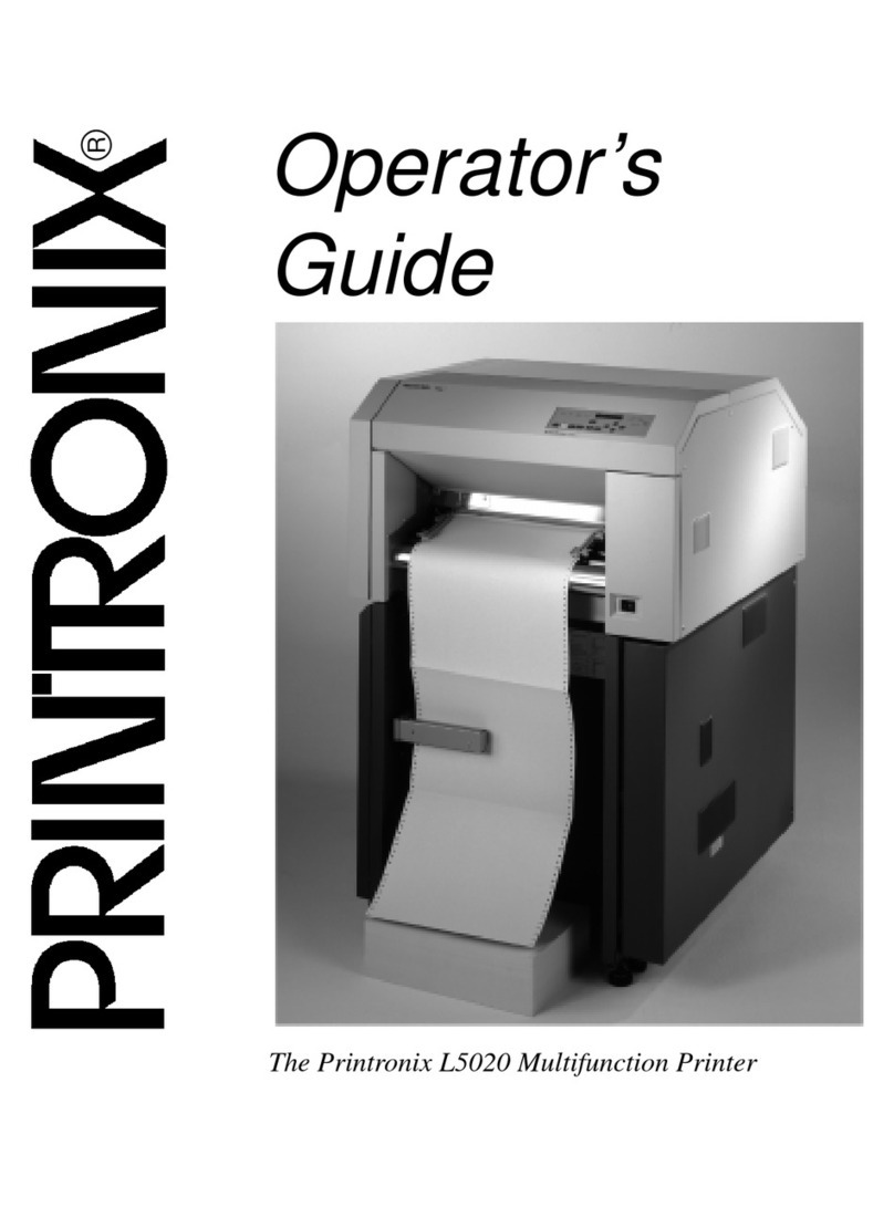
Printronix L5020 Manual

Printronix
Printronix L5535 User manual

Printronix
Printronix L5020 User manual

Printronix
Printronix P9012 User manual

