manuals.online logo
Brands
  1. Home
  2. •
  3. Brands
  4. •
  5. Wilo
  6. •
  7. Water Pump
  8. •
  9. Wilo NPG Series User manual

Wilo NPG Series User manual

This manual suits for next models

22

Other Wilo Water Pump manuals

Wilo Wilo-Economy CO-1/T-1 /CE+ /ER Series User manual

Wilo

Wilo Wilo-Economy CO-1/T-1 /CE+ /ER Series User manual

Wilo Drain TP 65 Series User manual

Wilo

Wilo Drain TP 65 Series User manual

Wilo Wilo-Rexa MINI3-V05-AU Series User manual

Wilo

Wilo Wilo-Rexa MINI3-V05-AU Series User manual

Wilo Drain LP 40 User manual

Wilo

Wilo Drain LP 40 User manual

Wilo Wilo-Star-Z 20/1 User manual

Wilo

Wilo Wilo-Star-Z 20/1 User manual

Wilo Rexa CUT GI Series User manual

Wilo

Wilo Rexa CUT GI Series User manual

Wilo COE-2 MHIL User manual

Wilo

Wilo COE-2 MHIL User manual

Wilo Star-Z 20/5 EM User manual

Wilo

Wilo Star-Z 20/5 EM User manual

Wilo Rexa MINI3-V-A Series User manual

Wilo

Wilo Rexa MINI3-V-A Series User manual

Wilo Drain LPC Series User manual

Wilo

Wilo Drain LPC Series User manual

Wilo Drain MTS 40 Series User manual

Wilo

Wilo Drain MTS 40 Series User manual

Wilo Wilo-DrainLift Con User manual

Wilo

Wilo Wilo-DrainLift Con User manual

Wilo EMU KS Series User manual

Wilo

Wilo EMU KS Series User manual

Wilo Yonos PICO-Z User manual

Wilo

Wilo Yonos PICO-Z User manual

Wilo SCPV User manual

Wilo

Wilo SCPV User manual

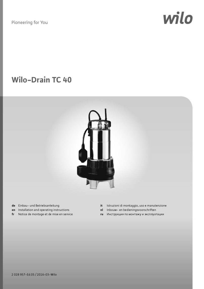
Wilo Drain TC 40 User manual

Wilo

Wilo Drain TC 40 User manual

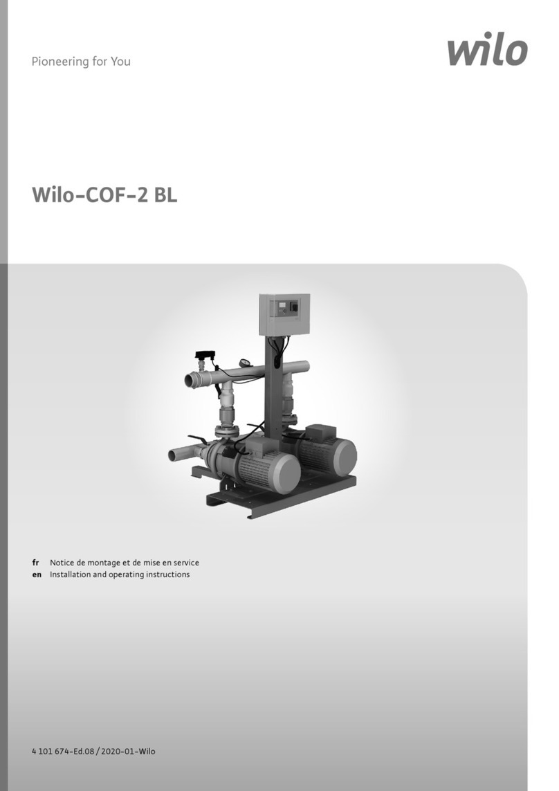
Wilo COF-2 BL User manual

Wilo

Wilo COF-2 BL User manual

Wilo Rexa FIT User manual

Wilo

Wilo Rexa FIT User manual

Wilo Jet WJ Series User manual

Wilo

Wilo Jet WJ Series User manual

Wilo HiDrainlift 3 Series User manual

Wilo

Wilo HiDrainlift 3 Series User manual

Wilo ISAR MODH1 Series User manual

Wilo

Wilo ISAR MODH1 Series User manual

Wilo Wilo-Star-Z NOVA User manual

Wilo

Wilo Wilo-Star-Z NOVA User manual

Wilo Wilo-Star RSD User manual

Wilo

Wilo Wilo-Star RSD User manual

Wilo Atmos GIGA-N User manual

Wilo

Wilo Atmos GIGA-N User manual

Popular Water Pump manuals by other brands

Watershed Innovations HYDRAPUMP SMART FLEX Instructional manual

Watershed Innovations

Watershed Innovations HYDRAPUMP SMART FLEX Instructional manual

Graco Modu-Flo AL-5M instructions

Graco

Graco Modu-Flo AL-5M instructions

Messner MultiSystem MPF 3000 operating instructions

Messner

Messner MultiSystem MPF 3000 operating instructions

Xylem Bell & Gossett WEHT0311M Installation, operation and maintenance instructions

Xylem

Xylem Bell & Gossett WEHT0311M Installation, operation and maintenance instructions

WilTec 50739 Operation manual

WilTec

WilTec 50739 Operation manual

Franklin Electric Little Giant 555702 HRK-360S instruction sheet

Franklin Electric

Franklin Electric Little Giant 555702 HRK-360S instruction sheet

Ingersoll-Rand PD02P Series Operator's manual

Ingersoll-Rand

Ingersoll-Rand PD02P Series Operator's manual

VS ZJ Series Operating	 instruction

VS

VS ZJ Series Operating instruction

Flotec FPZS50RP owner's manual

Flotec

Flotec FPZS50RP owner's manual

SKF Lincoln FlowMaster II User and maintenance instructions

SKF

SKF Lincoln FlowMaster II User and maintenance instructions

Xylem Lowara LSB Series Installation, operation and maintenance instructions

Xylem

Xylem Lowara LSB Series Installation, operation and maintenance instructions

Water Duro Pumps DCJ500 Operating & installation instructions

Water

Water Duro Pumps DCJ500 Operating & installation instructions

Action P490 Operating instructions & parts manual

Action

Action P490 Operating instructions & parts manual

Flo King Permacore Reusable Carbon Bag Disassembly. & Cleaning Instructions

Flo King

Flo King Permacore Reusable Carbon Bag Disassembly. & Cleaning Instructions

ARO ARO PD15P-X Operator's manual

ARO

ARO ARO PD15P-X Operator's manual

Pumptec 112V Series Operating instructions and parts manual

Pumptec

Pumptec 112V Series Operating instructions and parts manual

Virax 262070 user manual

Virax

Virax 262070 user manual

Neptun NPHW 5500 operating instructions

Neptun

Neptun NPHW 5500 operating instructions

manuals.online logo
manuals.online logoBrands
  • About & Mission
  • Contact us
  • Privacy Policy
  • Terms and Conditions

Copyright 2025 Manuals.Online. All Rights Reserved.

GBInstallation and operating instructions
Wilo-NPG
4095556/Ed_01_gb_0610_Wilo
ООО "ПромХимТех" - официальный поставщик насосов NL / NLG / NPG вРоссии иСНГ
www.promhimtech.ru / [email protected]
English
Installation and maintenance instructions Wilo-Horizontal pumps NPG
1 Introduction and Safety
1.1 General
These instructions must always be kept close to
the product's operating location or directly with
the product.
These instructions are intended to facilitate fami-
liarization with the product and its permitted use.
Operating the product in compliance with these
instructions is important to help ensure reliability
in service and avoid risks. The instructions may not
take into account local regulations; ensure such
regulations are observed by all, including those
installing the product. Always coordinate repair
activity with operations personnel, and follow all
plant safety requirements and applicable safety
and health laws and regulations.
These instructions should be read prior to
installing, operating, using and maintaining the
equipment in any region worldwide. The equip-
ment must not be put into service until all the
conditions relating to safety noted in the
instructions, have been met.
1.2 CE marking and approvals
It is a legal requirement that machinery and equip-
ment put into service within certain regions of the
world shall conform with the applicable
CE Marking Directives covering Machinery and,
where applicable, Low Voltage Equipment, Elec-
tromagnetic Compatibility (EMC), Pressure Equip-
ment Directive (PED).
Where applicable the Directives and any additional
Approvals cover important safety aspects relating
to machinery and equipment and the satisfactory
provision of technical documents and safety
instructions. Where applicable this document
incorporates information relevant to these Direc-
tives and Approvals.
To confirm the Approvals applying and if the pro-
duct is CE marked, check the serial number plate
markings and the Certification. (See section 9,
Certification.)
1.3 Disclaimer
Information in these User Instructions is belie-
ved to be reliable. In spite of all the efforts to
provide sound and all necessary information the
content of this manual may appear insufficient
and we don’t guarantee as to its completeness
or accuracy.
We manufacture products to exacting Internatio-
nal Quality Management System Standards as cer-
tified and audited by external Quality Assurance
organizations. Genuine parts and accessories have
been designed, tested and incorporated into the
products to help ensure their continued product
quality and performance in use.
Damage or failure caused by misuse is not covered
by the warranty. In addition, any modification of
products or removal of original components may
impair the safety of these products in their use.
1.4 Copyright
All rights reserved. No part of these instructions
may be reproduced, stored in a retrieval system or
transmitted in any form or by any means without
prior permission.
1.5 Duty conditions
The product must not be operated beyond the
parameters specified for the application. If there
is any doubt as to the suitability of the product
for the application intended, contact us for
advice, quoting the serial number.
If the conditions of service on your purchase order
are going to be changed (for example liquid pum-
ped, temperature or duty) it is requested that the
user seeks the written agreement of the company
before start up.
1.6 Safety
1.6.1 Summary of safety markings
These User Instructions contain specific safety
markings where non-observance of an instruction
would cause hazards. The specific safety markings
are:
This symbol indicates electrical safety instructions
where non-compliance will involve a high risk to
personal safety or the loss of life.
This symbol indicates safety instructions where
non-compliance would affect personal safety and
could result in loss of life.
This symbol indicates “hazardous and toxic fluid”
safety instructions where non-compliance would
affect personal safety and could result in loss of
life.
1.6.2 Personnel qualification and training
All personnel involved in the operation, installa-
tion, inspection and maintenance of the unit must
be qualified to carry out the work involved. If the
personnel in question do not already possess the
necessary knowledge and skill, appropriate trai-
ning and instruction must be provided.
This symbol indicates safety instructions
where non-compliance will involve some
risk to safe operation and personal safety
and would damage the equipment or pro-
perty.
This sign is not a safety symbol but indica-
tes an important instruction in the assem-
bly process.
CAUTION!
NOTE:
English
6Wilo AG 09/2005
1.6.3 Safety action
This is a summary of conditions and actions to
prevent injury to personnel and damage to the
environment and to equipment.
NEVER DO MAINTENANCE WORK WHEN THE
UNIT IS CONNECTED TO POWER
GUARDS MUST NOT BE REMOVED WHILE THE
PUMP IS OPERATIONAL
DRAIN THE PUMP AND ISOLATE PIPEWORK
BEFORE DISMANTLING THE PUMP
The appropriate safety precautions should be
taken where the pumped liquids are hazardous.
HANDLING COMPONENTS
Many precision parts have sharp corners and the
wearing of appropriate safety gloves and equip-
ment is required when handling these compon-
ents. To lift heavy pieces above 25 kg (55 lb) use
a crane appropriate for the mass and in accor-
dance with current local regulations.
THERMAL SHOCK
Rapid changes in the temperature of the liquid
within the pump can cause thermal shock, which
can result in damage or breakage of components
and should be avoided.
NEVER APPLY HEAT TO REMOVE IMPELLER
Trapped lubricant or vapour could cause an
explosion.
HOT (and cold) PARTS
If hot or freezing components or auxiliary hea-
ting supplies can present a danger to operators
and persons entering the immediate area action
must be taken to avoid accidental contact. If
complete protection is not possible, the
machine access must be limited to maintenance
staff only, with clear visual warnings and indica-
tors to those entering the immediate area. Note:
bearing housings must not be insulated and
drive motors and bearings may be hot.
If the temperature is greater than 68 °C (175 °F)
or below 5 °C (20 °F) in a restricted zone, or
exceeds local regulations, action as above shall
be taken.
HAZARDOUS LIQUIDS
When the pump is handling hazardous liquids
care must be taken to avoid exposure to the
liquid by appropriate sitting of the pump, limi-
ting personnel access and by operator training.
If the liquid is flammable and/or explosive, strict
safety procedures must be applied.
Gland packing must not be used when pumping
hazardous liquids.
1.7 Noise level
When pump noise level exceeds 85-dBA attention
must be given to prevailing Health and Safety
Legislation, to limit the exposure of plant opera-
ting personnel to the noise. The usual approach is
to control exposure time to the noise or to enclose
the machine to reduce emitted sound. You may
have already specified a limiting noise level when
the equipment was ordered, however if no noise
requirements were defined then machines above
a certain power level will exceed 85 dBA. In such
situations consideration must be given to the fit-
ting of an acoustic enclosure to meet local regula-
tions.
Pump noise level is dependent on a number of
factors - the type of motor fitted, the operating
capacity, pipework design and acoustic characte-
ristics of the building.
The figures in the table below are indicative only,
PREVENT EXCESSIVE EXTERNAL PIPE
LOAD
Do not use pump as a support for piping.
Do not mount expansion joints, so that
their force, due to internal pressure, acts
on the pump flange.
ENSURE CORRECT LUBRICATION
(See section 5, Commissioning, startup,
operation and shutdown.)
START THE PUMP WITH OUTLET VALVE
PARTLY OPENED
(Unless otherwise instructed at a speci-
fic point in the User Instructions.)
This is recommended to minimize the
risk of overloading and damaging the
pump motor at full or zero flow. Pumps
may be started with the valve further
open only on installations where this
situation cannot occur. The pump outlet
control valve may need to be adjusted to
comply with the duty following the run-
up process. (See section 5, Commissio-
ning start-up, operation and shutdown.)
NEVER RUN THE PUMP DRY
INLET VALVES TO BE FULLY OPEN WHEN
PUMP IS RUNNING
Running the pump at zero flow or below
the recommended minimum flow conti-
nuously will cause damage to the seal.
DO NOT RUN THE PUMP AT ABNOR-
MALLY HIGH OR LOW FLOW RATES
Operating at a flow rate higher than nor-
mal or at a flow rate with no backpres-
sure on the pump may overload the
motor and cause cavitations. Low flow
rates may cause a reduction in pump/
bearing life, overheating of the pump,
instability and cavitations/vibration.
CAUTION!
CAUTION!
CAUTION!
CAUTION!
CAUTION!
CAUTION!
English
Installation and maintenance instructions Wilo-Horizontal pumps NPG
they are subject to a +3 dB tolerance, and cannot
be guaranteed.
The values are based on the noisiest ungeared
electric motors which are likely to be encountered.
They represent Sound Pressure Levels at 1 m
(3.3 ft) from the directly driven pump, for "free
field over a reflecting plane".
If a pump only has been purchased, for fitting with
your own driver, then the "pump only" noise levels
from the table should be combined with the level
for the driver obtained from the supplier. If the
motor is driven by an inverter, it may show an
increase in noise level at some speeds. Consult a
Noise Specialist for the combined calculation.
In areas where the staff has to intervene, remem-
ber that when the level of the sound pressure is:
Below 70 dBA:
It is not necessary to take special precautions.
Above 70 dBA:
People working continuously in the machine room
must be supplied with protective devices against
noise.
Below 85 dBA :
No particular measures need to be taken for casual
visitors staying in the room during a limited period.
Above 85 dBA:
The room must be considered as a dangerous area
because of the noise and a warning sign must be
fixed at each entry warning the people coming
into the room, even for a short period, that they
must wear hearing protection.
Above 105 dBA:
Special hearing protection adapted to this noise
level and to the spectral noise components must
be installed and a warning sign to this effect erec-
ted at each entry. The staff in the room must
wear ear protection.
Make sure that the noise, which travels through
the walls and windows, does not generate too
high noise levels in the machine room's surroun-
dings.
2 Transport and storage
2.1 Consignment receipt and unpacking
Immediately after receipt of the equipment it
must be checked against the delivery and shipping
documents for its completeness and that there
has been no damage in transportation.
Any shortage and or damage must be reported
immediately and received in writing within one
month of receipt of the equipment. Later claims
cannot be accepted.
Check any crate, boxes and wrappings for any
accessories or spare parts that may be packed
separately with the equipment or attached to
Typical sound pressure level,
dBA, LpA at 1 m reference 20 PPa (LwA sound power1 pW where LpA >85dBA)
Motor size and speed 3550 r/min 2900 r/min 1750 r/min 1450 r/min
Pumpand
motor
Pump
only
Pump and
motor
Pump
only
Pumpand
motor
Pump
only
Pumpand
motor
Pump
only
kW (hp) dBA dBA dBA dBA dBA dBA dBA dBA
<0.55 (<0.75) 71 66 64 62 64 62 63 62
0.75(1) 7466676267626362
1.1 (1.5) 74 68 67 64 67 64 65 64
1.5 (2) 77 70 70 66 70 66 66 66
2.2 (3) 78 72 71 68 71 68 68 68
3 (4) 81 74 74 70 74 70 70 70
4 (5) 82 75 75 71 75 71 71 71
5.5 (7.5) 90 (99) 77 83 73 76 73 72 71
7.5 (10) 90 (99) 78 83 74 77 74 73 72
11 (15) 91 (100) 80 84 76 78 76 74 73
15 (20) 92 (101) 83 85 (94) 79 80 79 76 75
18.5 (25) 92 (101) 83 85 (94) 79 80 79 76 75
22 (30) 92 (101) 83 85 (94) 79 81 79 77 75
30 (40) 100 (109) 85 (94) 93 (102) 81 84 80 80 76
37 (50) 100 (109) 86 (95) 93 (102) 82 84 80 80 76
45 (60) 100 (109) 87 (96) 93 (102) 83 84 80 80 76
55 (75) 100 (109) 88 (97) 95 (104) 84 86 (95) 81 82 77
75 (100) 100 (109) 90 (99) 95 (104) 86 (95) 88 (97) 81 83 78
90 (120) 100 (109) 90 (99) 95 (104) 86 (95) 90 (99) 81 85 (94) 78
110 (150) 100 (109) 91 (100) 95 (104) 87 (96) 91 (100) 83 86 (95) 79
150 (200) 101 (110) 92 (101) 96 (105) 88 (97) 91 (100) 83 86 (95) 79
English
8Wilo AG 09/2005
sidewalls of the box or equipment.
Each product has a unique serial number. Check
that this number corresponds with that advised
and always quote this number in correspondence
as well as when ordering spare parts or further
accessories.
2.2 Handling
2.2.1 General instructions concerning handling
Boxes, crates, pallets or cartons may be unloaded
using forklift vehicles or slings dependent on their
size and construction. See 2.3.1 for positioning of
slings.
To lift heavy pieces above 25 kg (55 lb), use a
winch adapted to the mass and in accordance with
the current local regulations.
To lift machines or pieces with one or several sus-
pension rings, only use hooks and chains in com-
pliance with the local regulations concerning
safety. Never put cables, chains or ropes directly
on or in the suspension rings. Cables, chains or lif-
ting ropes must never present excessive bending.
Never bend the lifting hooks, suspension rings,
chains, etc., which should only be made to endure
stresses within, calculated limits. Remember that
the capacity of a lifting device decreases when the
direction of the lifting force direction makes an
angle with the device axis.
To increase the safety and the efficiency of the lif-
ting device, all the lifting elements must be as
perpendicular as possible. If necessary a lifting
beam can be placed between the winch and the
load.
When heavy pieces are lifted up, never stay or
work under the load or in the area, which could be
in the path of the load if it were to swing or fall
away. Never leave a load hanging from a winch.
The acceleration or the slowing-down of lifting
equipment must stay in the safety limits for the
staff.
A winch must be positioned in such a way that the
load will be raised perpendicularly. Where possible
necessary precautions must be taken to avoid the
swing of the load, using for example two winches
making approximately the same angle, below 30°,
with the vertical.
2.2.2 Pump masses
All motors (for masses see the motor description
plate) must be handled with a winch.
For masses above 25 kg (55 lb), manual handling
is forbidden.
2.3 Lifting
2.3.1 Slinging of motor pumps units
Use handling means in accordance with motor
pump unit mass mentioned on the CE plate. For
the masses of the pumps bare end of shaft see
table § 2.2.2 and nameplate.
Pump type Pump mass (kg)
NPG65 – 315 140
NPG100 – 315 160
NPG150 - 200 130
NPG150 - 500 475
NPG200 - 250 175
NPG200 - 315 260
NPG200 - 355 265
NPG200 - 400 370
NPG200 - 500 420
NPG250 - 250 290
NPG250 - 315 330
NPG250 - 355 370
NPG250- -400 415
NPG250 - 500 500
NPG300 - 300 370
NPG300 - 400 480
NPG300 - 450 550
NPG300 - 500 710
NPG350 - 350 700
NPG400 - 500 1100
NPG400 - 650 1250
NPG500 - 500 1450
To avoid distortion, the pump unit
should be lifted as shown.
Motor pump unit
CAUTION!
English
Installation and maintenance instructions Wilo-Horizontal pumps NPG
When handling always wear gloves, safety boots
and an industrial safety helmet.
For masses above 25 kg (55 lb), manual handling
is forbidden.
2.4 Storage
Do not store pumps starting on the fan guard.
The pump may be stored as above for up to 6
months. Consult us for preservative actions when
a longer storage period is needed.
2.5 Recycling and end of product life
At the end of the service life of the product or its
parts, the relevant materials and parts should be
recycled or disposed of using an environmentally
acceptable method and local regulations. If the
product contains substances that are harmful to
the environment, these should be removed and
disposed of in accordance with current regulati-
ons. This also includes the liquids and or gases that
may be used in the "seal system" or other utilities.
Make sure that hazardous substances are dis-
posed of safely and that the correct personal
protective equipment is used. The safety speci-
fications must be in accordance with the current
regulations at all times.
3 Pump Description
3.1 Configurations
The centrifugal motor pump unit is designed for
the pumping of cold water or all clear liquids which
are not solid and liquid mixtures, corrosive, abra-
sive or explosive when in contact with the pump
motor unit and its working parts (Important: for
other liquids consult us for preliminary advice).
The NPGtype pump is a single-stage pump with
axial suction, support under pump casing (Stan-
dard NF EN 733) and tangential vertical discharge.
The pumps of this range allow to the removal of
the pump rotor whilst leaving the pump casing
connected to the suction and discharge pipework.
The pump must be stored in a non-explosive,
ventilated location, sheltered from bad weather,
dust and vibrations.
The reliability of the delivered machine can only
be ensured if it is used according to the conditions
given in this manual. The maximum values speci-
fied in this manual must never be exceeded..
Bareshaft pump
Store the pump in a clean, dry location
away from vibration. Leave piping con-
nection covers in place to keep dirt and
other foreign material out of pump
casing. Turn pump at intervals to pre-
vent brinelling of the bearings and the
seal faces, if fitted, from sticking.
CAUTION!
Maximum working pressure at suc-
tion:
in the limit of the
maximum working
pressure at discharge
for zero flow accor-
ding to the pump
type
Maximum pumped fluid temperature
• Gland packing without cooling: d105 °C
• Mechanical seal without cooling:
•ACSversion d80 °C
• Standard version d140 °C
Maximum solid suspension 50 g/m3
Density 1
Viscosity 1
Frequency 50 Hz
Maximum speed
• for all pumps exept 1450 min-1
•forNPG400-500, NPG400-650,
NPG500-500
990 min-1
•forNPG65-315 , NPG100-315 2900 min-1
English
10 Wilo AG 09/2005
3.2 Nomenclature
Designation of pump:
Each pump is supplied with the following name-
plate:
4Installation
4.1 Location
The pump should be located to allow room for
access, ventilation, maintenance and inspection
with ample headroom for lifting and should be as
close as practicable to the supply of liquid to be
pumped.
Maximum effective pressure at discharge in bar
NPG(cast iron EN-GJL-250) - PN 10 NPG(cast iron EN GJS-400-15) - PN 16 - PN 10

Impeller
DN
150
DN
200
DN
250
DN
300
DN
350
DN
400
DN
500
DN
150
DN
200
DN
250
DN
300
DN
350
DN
400
DN
500
200 4 6
250 4 4 6 6
300 4 6
315 8 8 12 12
350 4 6
355 8 8 12 12
400 8 8 8 12 12 12
450 8 12
500 16 10 10 10 6.5 4 15 15 15 10 6
650 6.5 10
NPG200 / 315 - 37 / 4-12 - ...
NPGType of pump WILO
200 Nominal width of pipe mount
315 Diameter of impeller
37 Power of motor
4 2 or 4 poles motor
12 05 Mechanical seal-standard coupling
12 Mechanical seal-coupling with
spacer
01 Packing gland-standard coupling
02 Packing gland-coupling with spacer
XX Other design
... Options
Nameplate
1 Type of pump
2 Flow rate
3Head
4 Date of construction and article number
5 Diameter of impeller
6 Speed of rotation
7Mass
8 Maximum admissible pressure at 20 °C
9 Maxi/Mini temperature
10 Radial/Thrust bearing
1
2
3
4
5
6
7
8
9
10
English
Installation and maintenance instructions Wilo-Horizontal pumps NPG
4.2 Foundation
The base plate should be mounted onto a firm
foundation, either an appropriate thickness of
quality concrete or sturdy steel framework. It
should NOT be distorted or pulled down onto the
surface of the foundation, but should be suppor-
ted to maintain the original alignment.
Anchor bolts must be in accordance with the foot
bolt holes. Use anchor bolts of accepted standards
and sufficient to ensure seave fitting in the foun-
dation.
Provide sufficient space in the foundation to
accommodate the anchor bolts. If necessary, pro-
vide concrete risers.
Usually the pump and its drive are mounted on a
common base plate.
4.2.1 Setting the base plate for anchoring
• Clean the foundation surface thoroughly.
• Put shims on the foundation surface (approx 20-
25 mm thick), one on each side of the bolt hole (as
an alternative, leveling screws can be used). .
• Lay the base plate and level in both directions with
extra shims. The base plate should be level to
within 0.5 mm per 1 m.
If anchor bolts have been pre-cast in the founda-
tion slightly tighten the anchor bolts. Otherwise
let them hang in the foundation holes.
4.3 Initial alignment
There are many methods of installing
pump units to their foundations. The
correct method depends on the size of
the pump unit, its location and noise vib-
ration limitations. Non-compliance with
the provision of correct foundation and
installation may lead to failure of the
pump and, as such, would be outside the
terms of the warranty.
Type of
base
Article
number
Length
mm 
mm
Length
thread mm
4 740707 300 20 60
5 740708
6 740709
7 740710 300 24 100
8 740711
9 740712
10 4084125
CAUTION!
Before connecting the couplings verify
the motor rotation direction.
CAUTION!
English
12 Wilo AG 09/2005
4.3.1 Thermal expansion
4.3.2 Alignment methods
Ensure pump and driver are isolated electrically
and the half couplings are disconnected. Ensure
that the pump pipework, suction and discharge,
is disconnected.
Although the pump will have been aligned at the
factory it is most likely that this alignment will
have been disturbed during transportation or
handling. If necessary, align the motor to the
pump, not the pump to the motor.
Alignment
Parallelism and concentricity check:
Admissible margin for a motor with roller bearings:
= 0.15 mm parallel checking
= 0.1 mm angular checking
If necessary, improve the machine alignment:
Complete unit mounted on common base plate:
The machines are first aligned accurately in our
workshops. Usually, any misalignment observed
on-site is due to a wrong adjustment under the
base plate (disturbed during transport or because
of forces exerted by the pipework). It is only
necessary to rectify the adjustment under base
plate. If it proves to be insufficient, modify the
motor and the pipeworks adjustment.
Never connect the electric motor before the
setting has been completely finished.
The pump and motor will normally have
to be aligned at ambient temperature
and should be corrected to allow for
thermal expansion at operating tempe-
rature. In pump installations involving
high liquid temperatures, the unit should
be run at the actual operating tempera-
ture, shut down and the alignment che-
cked immediately.
The alignment MUST be checked.
Check the alignment at three or four
points, before pipeworks assembly.
The alignment will be definitive only
after pipework connection (see § 4.4.4.).
CAUTION!
CAUTION!
CAUTION!
with a rule with a comparator
with a sliding rule with a caliper gauge
CAUTION!
English
Installation and maintenance instructions Wilo-Horizontal pumps NPG
4.4 Piping
4.4.1 Suction and discharge pipework
The dimensions of the pipes do not directly
depend on suction and discharge diameters of the
pump.
a) First, choose a flow speed < 2 m/s at suction,
and about 3 m/s at discharge.
b) Take into account the available NPSH, which
must be superior to the required NPSH of the
pump.
Never use pump as a support for piping. Do not
mount expansion joints in such a way that their
force, due to internal pressure, may act on the
pump flange.
Maximum forces and moments allowed on the
pump flanges vary with the pump size and type.
These external strains may cause misalignment,
hot bearings, worn couplings, vibrations and the
possible failure of the pump casing.
When designing the pipes (§ 4.4.2.1, § 4.4.2.2,
§ 4.4.3.1) take necessary precautions in order not
to exceed maximum allowed strains.
Forces and moments applied to the pump flanges
must never exceed the values shown in the table
below:
Forces and moments values are applied to the
whole flanges and not flange-by-flange. For their
sharing out on the pump flanges, refer to standard
NFCR 13 931.
4.4.2 Suction piping
4.4.2.1 Design of a flooded suction line
The suction line must be as short and direct as
possible, never mount an elbow directly on the
Protective covers are fitted to the pipe
connections to prevent foreign bodies
entering during transportation and
installation. Ensure that these covers are
removed from the pump before connec-
ting any pipes.
CAUTION!
DN
Flange
Forces (daN) Moments (m.daN)
Fy Fz Fx ¦FMy Mz Mx ¦M
Vertical Discharge 150 160 200 180 310 45 60 80 110
200 215 265 240 415 85 100 125 180
250 270 335 300 520 125 145 180 260
300 320 400 360 625 170 200 240 355
350 375 465 420 730 220 255 310 455
400 430 530 480 835 275 320 390 570
450 485 600 540 940 340 390 480 705
500 540 665 600 1040 410 470 580 850
Horizontal Suction 150 180 160 200 315 45 60 80 110
200 240 215 265 415 85 100 125 180
250 300 270 335 520 125 145 180 260
300 360 320 400 625 170 200 240 355
350 420 375 465 730 220 255 310 455
400 480 430 530 835 275 320 390 570
450 540 485 600 940 340 390 480 705
500 600 540 665 1040 410 470 580 850
Ensure piping and fittings are flushed
before use.
CAUTION!
Ensure piping for hazardous liquids is
arranged to allow pump flushing before
removal of the pump.
CAUTION!