Prism Medical UK transactive tra User manual

Freeway Healthcare, Integra 200, St Asaph Business Park, St Asaph,
Denbighshire, North ales, LL17 0LJ,
Tel: 01745 536 780 Fax: 01745 582 532
Technical
Manual
Troubleshooting
Repairs
Replacements

Technical manual August 2009
Rev: 01/08/09 Page:
2
Transactive-Xtra
Table of Contents
Symptoms and Problems
Finding the Problem – Before Getting Inside
3
Pneumatic Systems
4
Electrical Systems
5
Mechanical Systems
8
Basic Instruction Sheets
B1 - Getting Access to the Transactive-Xtra 11
Pneumatic Instruction Sheets
P1 - Replace Hand Control & Airline Tubing – Air Leak Test 13
P2 - Replace Grommet
14
P3 - Faulty Main and Auxiliary PCB Air Switches
15
Electrical Instruction Sheets
E1 - Test and/or Replace Batteries
16
E2 - Replace Main and Auxiliary PCB (Printed Circuit Board)
17
E3 - Repair/replace Charger and End Stop 18
E4 - Repair Charger Contact Strips and Wire Harnesses (LED) 19
E5 - Adjust/Replace UP/DOWN Micro Switch Assembly 20
E6 - Repair/Replace Emergency Shut-off with Pull Cord 22
Mechanical Instruction Sheets
M1 - Replace Lifting Strap – Frayed, Stress Streaks, Length
23
M2 - Replace Trolley Wheels
24
M3 - Replace Traversing Drive Motor, Traversing Gear and Traverse Idle Gear
25
LCD Display & Programming Functionality
26
Tool List
31
Wiring Diagrams
D1 - Main PCB (Printed Circuit Board) Schematic Diagram 32
D2 - Auxiliary PCB (Printed Circuit Board) Schematic Diagram 33
Service Parts List
34

Technical manual August 2009
Rev: 01/08/09 Page:
3
SYMPTOMS AND PROBLEMS
Finding the Problem – Before Getting Inside
Please note that the majority of technical problems that can occur with the Transactive-Xtra
occur with external system components. The following are the key components to check before
removing any lift cover:
•Transformer and Charge Connections
•Switched fused spur
•Hand Control and Airline Problems
•Twisted Strap or Slack Tape Issues
•External Thermal Breaker
•Review Trouble Shooting Points in Owner’s Manual
The hoist is a pneumatically operated electro-mechanical device. To diagnose performance
interruption it is useful to think of the product as three separate systems:
1. Pneumatic System
•Hand Control Unit
•Airline Tubing (2, 4, 6-way)
•Grommet Connectors
•Connector Pins
•Air Tubes
•Air Receiver Mechanism
2. Electrical System
•Transformer, Charger PCB and Charger Connections
•Main PCB – Printed Circuit Board
•Auxiliary PCB - Printed Circuit Board
•Wire Harnesses
•Microswitch Up Limit Switch
•Microswitch Down Limit switch
•Quick Disconnects
•LED Indicator & LCD Display
•Electric ON/OFF, Emergency Lowering and Emergency Shut-Off
3. Mechanical System
•Carry Bar or Lifting Hook
•Lifting Strap
•Tape Switch Assembly
•Motors and Gears
•Trolley Wheels and Chain Drives

Technical manual August 2009
Rev: 01/08/09 Page:
4
Pneumatic Systems
The pneumatically operated functions control on/off, up, down and, where applicable, the side-to-
side traversing motion of the hoist. A methodical check of the pneumatic system starts from the
hand control and works forward through the pneumatic switches on the circuit board.
1. Hand control & Airline
•Unplug the hand control airline from the hoist and check for blockage of the airlines by
pressing each of the function buttons in turn. Next, check for leaks in the hand control and
airlines by pressing a function button with one thumb, then cover the pins at the end of the
airline with the other thumb, then lift the first thumb off the function button. The button
should remain depressed when the thumb is lifted. Repeat for each button. If the buttons
do not remain depressed, there is an air leak and the hand control unit should be replaced.
2. Air tubes
•Re-attach the hand control airline to the hoist. (The airline end plug has a cap that has a
raised ridge on one face. The raised cap ridge aligns with and slides over the ridge on the
grommet. Correct insertion can thus be verified by touch and by sight.) Check to see that
the air tubes have been routed free and clear. If not routed properly, air tubes can get
trapped by wires, other hoist components or the hoist cover.
•Check to see that the air tubes are correctly connected to the circuit board switches. The
two air tubes attached to the main board are color coded to correspond to the colored
stickers on the switches. The two air tubes attached to each of the traversing boards are
connected on the principle of “nearest tube to nearest switch.”
•Next detach one air tube at a time from the circuit board. Check for leaks in an air tube by
pressing the function key corresponding to that air tube (the function is indicated on the
color coded stickers on the switches), then pinch the open end of the air tube between two
fingers, then release the function button. The button should stay down when the button is
released. Repeat for each air tube.
•Air tubes are fragile. In detaching and re-attaching air tubes, do not press on the air tubes
with fingernails and be careful not to pierce the tubes with the connector pins.
If an air leak is found the hand control needs to be replaced.
If NO air leak is found then proceed to check the electrical system.

Technical manual August 2009
Rev: 01/08/09 Page:
5
Electrical Systems
Ensure that the batteries are charged. Turn the hoist on & look at the LCD reading to check the
battery charge level. If the batteries are not charged, put them on charge before servicing the
equipment or connect a fresh set of batteries. If the charger indicator does not give any reading,
batteries can be tested “outside the system” with a load tester or, again, a fresh set of batteries
should be hooked up. An occasional battery problem is acid leaks at the vents. Sometimes a leak
shows up as corrosion of the battery leads.
Do a preliminary inspection of the circuit boards for burn marks or burns odours. A single or
series of components may have failed. The PCB will have to be replaced.
When an electrical problem seems to be the cause of the malfunction, it is important to first check
that all the wire harnesses are plugged in. Secondly it is important to check all wire harnesses for
cuts and/or exposed wires. If this is found, the wire harness must be replaced.
1. The main board on manual and power traversing systems
The white power plug, second from left, connects the batteries to the circuit board. The circuit
board is connected to the main motor via the white plug on the right most side of the board. The
board and main motor plugs are shaped to prevent erroneous hook-up. The battery cables are
color-coded black and red to match the battery leads. Check to see that the board, lift motor
and battery plugs are properly connected.
The 2-pin white plug on the far PCB side, is the connection point for the charger PCB to the main
PCB. The 3-pin white plug, first on the left, connects the LED indicator to the PCB. The 16-pin
connector, third from the left connects the LCD display to the PCB. The 4-pin white plug, second
from the right, connects the “slack tape” and “tape thickness” limit switches on the tape switch
assembly to the circuit board. Check to see that the functionality plugs are properly connected
(when connecting a plug, it is easy to miss a prong) and that the wires do not pull out of the
functionality plugs (if a wire does pull out, it was either connected incompletely or connected
upside down).
2. The auxiliary board(s) on power traversing systems
The auxiliary boards plug directly into the main board. The large 2-pin white plug connects the
PCB to the auxiliary motor. Check to see that the auxiliary board and auxiliary motor plugs are
properly inserted.
3. The charger board on all models
The 2 pin green plug on the right is where the charging beak plugs in. The 3 pin green plug on the
left is where the connection between the charger PCB and the main PCB is connected. Check the
input and output voltages as per section E1.
NOTE: Not all hoists will come with auxiliary PCB’s, Manual hoists have no auxiliary PCB’s, Drive
hoists have 1 Auxiliary PCB and Power H system hoists have 2 auxiliary PCB’s.

Technical manual August 2009
Rev: 01/08/09 Page:
6
Electrical Systems
Auxiliary PCB’s on main PCB
Display
Battery Cable
Charger PCB output cable
Power Switch Cable
Auxiliary Traverse Motor Cable
Front side of main PCB
Limit Switch
LED
Charger PCB
Charging beak cable
Charger output
cable

Technical manual August 2009
Rev: 01/08/09 Page:
7
Electrical Systems
3. If the batteries and circuit boards appear in order, no air leak is found and no fault is
found with the wiring
•Proceed to check that the lift and traversing motors are functioning by removing the
motor and battery leads and running jumper cables from the motor leads to the battery
leads. (Reversing polarity causes the motors run in reverse)
4. If the batteries and circuit boards appear in order, no air leak is found and no fault is
found with the wiring or with the motors
•The most likely cause of failure is a blown fuse on the circuit board. To confirm, check
the fuses on the board and verify they are both operable. If a fuse is blown replace it
with another 15 amp fuse and test the hoist. Under no circumstances should a fuse
with a fuse rating other than 15 amps be used. Using such a fuse can result in damage
to the hoist and /or personal injury. If the problem persists after testing, replace the
circuit board. If the problem still persists contact customer service on 01745 536780.
•The other likely cause of failure is a circuit board failure that is not readily visible. To
confirm, connect the non-functioning hoist to a board from service parts or from another
hoist. (There is no need for a complete board installation: the replacement board used
for confirmation can be hooked up provisionally outside the hoist.)
5. If the on/off buttons (and/or emergency lowering buttons) on both the hand control
and the hoist do not work
•Check the Emergency Shut-Off with Pull Cord. If it has been activated during an
emergency, call customer service. If it has been activated accidentally push the button
towards the hoist until you hear a click. This will allow you to operate the hoist again. If
the hoist still fails to operate examine the Emergency Shut-Off assembly to make sure
it is not obstructed and activates and deactivates the switch, repair as required. If the
problem persists, replace the Emergency Shut-Off switch.

Technical manual August 2009
Rev: 01/08/09 Page:
8
Mechanical Systems
1. If the hoist goes down to the end of the strap and then goes up again with the up and
down functions reversed, the “slack strap” safety feature is not working:
•Because the roller assembly inside the tape switch assembly is stuck and is therefore
not activating the micro switch. Clean the inside assembly of all debris and make sure
all parts are loose. Then check for the click of the switch as the roller assembly comes
to the end of the slot. If there is no click, The 2 switch screws should be loosened and
the switch pushed closer to the tape switch roller. Make sure that nothing is stuck or
jammed in the assembly.
•Because the switch is too close to the roller assembly. The 2 switch screws should be
loosened and the switch pushed farther away from the tape switch roller.
•Because of a wiring problem. Check the wiring from the tape switch assembly to the
main circuit board.
•Because the micro switch is malfunctioning. Replace the switch.
2. The hoist intermittently performs a pneumatically controlled function by itself
(pneumatically controlled functions are on/off, emergency lowering, up, down and,
where applicable, power traversing of hoist and power H system)
•There is likely a slow leak in the pneumatic system. The first elements of the pneumatic
system to be checked are the grommets (there is one on the hand control and one on
the hoist). For a complete check of the pneumatic system, see sections P1 to P4.
Frequent detachment and re-attachment of the airline or rough usage causes wear and
tear in the air holes of the grommets. Clients should NEVER use the hand
control/airline to pull the hoist along the track.
The strap goes all the way into the gearbox
The “thick strap” safety feature is not working:
•Because the moving roller assembly does not activate the switch. Introduce a slight
bend in the metal strip (which activates the switch) such that activation takes place
when a double thickness of strap is forced between moving rollers inside the tape
switch assembly. Make sure that nothing is stuck or jammed in the assembly.
Bend the limit switch strip to ensure
activation

Technical manual August 2009
Rev: 01/08/09 Page:
9
Mechanical Systems
•Because of a wiring problem. Check the wiring from tape switch assembly to the main
circuit board.
•Because the Microswitch is malfunctioning. Replace the switch or re-align it.
3. The hoist traverses poorly at specific points in the track system
Identify the points of blockage:
•Is the blockage at the seam of two pieces of track? Correct the vertical and/or
horizontal alignment.
•Is the blockage in a curved section? Check the curve for clearance. Replace an
improperly bent curve.
•Is the blockage in a turntable? Check the vertical and/or horizontal alignment of
turntable and track. Brackets should be used to “force” permanent proper alignment.
•Clean inside of track.
4. The hoist does not power traverse well anywhere along the track
Open up the hoist and check the alignment of the traversing system. There should be little
noise in the gears and minimal sway in the motor bracket when the motor is running.
Ensuring that the motor is tightly fastened and the gears are mounted securely, aligned
with each other can eliminate “Laboured noise and excessive sway”.
5. The hoist motor seems to be running, but does not work in UP or DOWN direction.
The motor output shaft or worm wheel of the motor may have worn. The acceleration
activated the overspeed governor, which is designed to prevent further use until the hoist
has been repaired. (The overspeed governor is a universal, failsafe mechanical brake,
which is triggered by centrifugal force and functions independently of the hoist’s pneumatic
electro-mechanical system.) Replace the motor.

Technical manual August 2009
Rev: 01/08/09 Page:
10
Mechanical Systems
6. The charger system does not work
The hoist charger system has six components: a switched fused spur, Transformer,
charging station end stop, charger plates, wiring harness and circuit board.
•Check to see that power is coming into the transformer: this can be done by measuring
the output voltage across the 2 stainless steel strips with a multimeter.
•Check to see that the charging strips of the charging station (bent in a wave pattern
with the middle section tensed and clear) make contact with the stainless steel contacts
on the trolley block.
•Check the correct rated fuse has been fitted to the switched fused spur (min 2 amp,
max 3 amp).
•Check the board by plugging the charging beak into a replacement board.
7. The on/off buttons (and/or emergency lowering buttons) on the hand control and the
hoist do not work
•Simultaneous failure of the pneumatic and electrical systems strongly indicate a circuit
board failure. Confirm this by hooking a replacement board. In the case of emergency
lowering, if the replacement board does not resolve the problem, the fault is in the
“slack tape” lower limit switch. (See point #1 ‘If the hoist goes down to the end of the
strap and then goes up again with up and down functions reversed.’)

Technical manual August 2009
Rev: 01/08/09 Page:
11
BASIC INSTRUCTION SHEETS
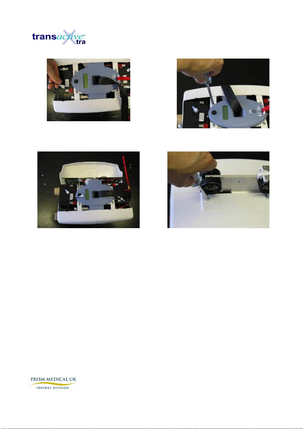
B1 - Getting Access to the Transactive-Xtra
IMPORTANT NOTE: Service hoist in a clean, dust free environment. Extreme care must be
exercised when removing the cover. Electric shock can occur.
1. Use support blocks to keep hoist balanced while servicing.
2. Disconnect the hand control airline tubing from the black grommet on the hoist unit.
3. Grasp the middle bottom cover at one of the short sides, pressing inwards to allow the tab
there to be snapped out. Repeat this on the opposite short side and then pull the cover
away from the hoist along its length to remove it.
4. IMMEDIATELY disconnect the RED wire lead to the batteries to prevent shock and damage.
5. Now the batteries are accessible for replacement and can be taken out once their tab
brackets are removed.
6. Remove two screws from the bottom face of one of the side covers.
7. Turn the hoist unit over to the opposite side and remove the two remaining screws from the
top face of the same cover.
8. Use caution when handling hoist. The stand-offs supporting the PCB are easily snapped off
if the hoist is not properly supported.
9. Be extremely careful and remember that the back of the PCB (Printed Circuit Board) will be
exposed. Contact with metal will short and destroy the PCB. Usage of proper E.S.D.
protection to prevent damage to the circuit board is highly recommended.
10. Remove this cover, detaching it from the elliptical, centre control cover. Place screws in the
side cover and use it to hold all loose parts.
11. Repeat Steps 6 – 10 for the remaining side cover.
2
3 3
Technical manual August 2009
Rev: 01/08/09 Page:
12
Disconnect Batteries
Remove side cover bottom screws
Remove side covers
Remove side cover top screws
Remove airline Detach bottom cover at one short
side tab Repeat on opposite side & pull off
cover along length of the hoist
Technical manual August 2009
Rev: 01/08/09 Page:
13
PNEUMATIC INSTRUCTION SHEETS
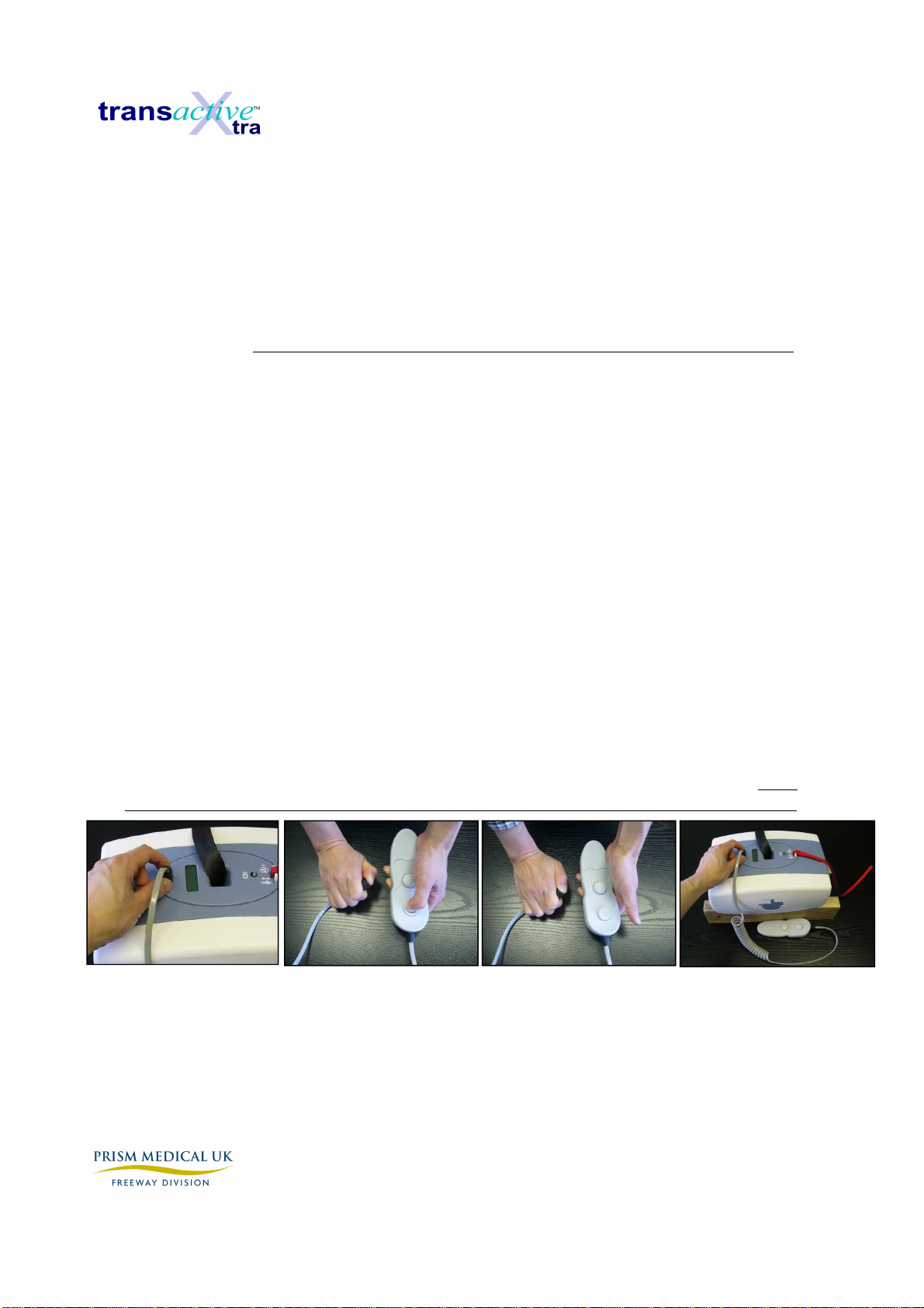
P1 - Replace Hand Control & Airline Tubing - Air Leak Test
IMPORTANT
NOTE: If an air leak is suspected, it is important to check the entire pneumatic
system for air leaks. There are NO serviceable parts inside the pneumatic Hand Control.
1. Separate the Airline tubing from the black grommet on the hoist unit.
2. Take note of the force required to separate these items. The connection should be very tight.
If the connection appears somewhat loose, an air leak may develop and cause a problem.
3. Test for air leaks in each Button separately, by depressing a button.
4. Hold the Hand Control and place a finger over the end of airline tubing.
5. Release the depressed button. If button stays in the depressed position, there are no air
leaks in the button. If button rises slowly after a few seconds, an air leak MAY be present.
Repeat a couple of times to ensure that the end of the airline tubing is completely covered.
6. Repeat Steps 2 to 4 for each button in turn.
7. Air leaks occur at the grommet connections because the hand control and airline tubing are
frequently used to pull the hoist along the track. This results in the frequent disconnection of
the airline and grommet.
8. Remember to reassemble the airline to the black grommet by aligning the ribs. If not
connected correctly, operating buttons on the hand control will not function properly.
Release button & test Separate airline Depress button & hold Rejoin airline

Technical manual August 2009
Rev: 01/08/09 Page:
14
P2 - Replace Grommet
IMPORTANT
NOTE: There are NO serviceable parts inside the pneumatic Hand Control.
1. If an air leak is suspected but there is no detected failure from test P1, there may be an air
leak at the hoist grommet because the airline pins do not fit tightly. This hoist grommet may
be replaced using the following steps.
2. Follow steps 1 - 12 in section B1.
3. Remove the battery on the side of the hoist nearest to the grommet. See section E1.
4. Before starting, take note of the positions of the individual airline tubes inside the hoist unit.
These should be marked in a way that they can be replaced in the exact same places.
Check the wire diagrams if not sure.
5. Lift away the blue oval plate to access the damaged grommet & clasp & flatten the rubber
using pliers to reduce the diameter enough to fit through the mounting hole. Then gently rock
the grommet back and forth while PUSHING the grommet through the hoist control panel.
6. Disconnect the airline tubing from PCB to the grommet & discard the damaged grommet.
7. Replace the new grommet by gently PULLING the grommet through the hoist control panel.
8. Reattach the internal air tubes and replace covers to reattach hand control airline.
9. Retest the entire pneumatic system to ensure that all hand control buttons function.
Compress grommet Gently push through Remove air tubes Reattach airline

Technical manual August 2009
Rev: 01/08/09 Page:
15
P3 – Faulty Main and Auxiliary PCB Air Switches
IMPORTANT
NOTE: There are no serviceable parts on the Main and Auxiliary PCB. These air
switches are not serviceable and the whole board must be replaced if they fail. As this is part of
the pneumatic system, it is important that all connections are airtight. Please note that not all hoist
will come with auxiliary PCB’s, Manual hoists have no auxiliary PCB’s, drive hoists have 1
Auxiliary PCB and power H systems have 2 auxiliary PCB’s.
1. If there are no leaks in the hand control, airline tubing and grommets, there could be a leak
in air tubes to the pressure switch or failure of air switch. Check by performing the air leak
test with the hand control buttons.
2. If there is an air leak, tighten all air tubes and recheck.
Auxiliary PCB’s with air
switches on main PCB
Up
Down
X+
X
-
Front side of main PCB
with air switches

Technical manual August 2009
Rev: 01/08/09 Page:
16
ELECTRICAL INSTRUCTON SHEETS
E1 - Test and/or Replace Batteries
IMPORTANT
NOTE: Sealed Lead Acid batteries must be handled with extreme care. Any
leakage or warpage of the battery cover indicates battery failure. Replace immediately.
1. If the indicator light (LED) on the control panel turns RED and an audible alarm sounds,
the batteries may not have sufficient power to operate the hoist under load. Hoist should
be returned to charger.
2. Using a multimeter (set for 100 volts DC) measure the voltage across the RED and Black
wire terminals on the batteries. The reading should be greater than 27.5 VDC if fully
charged.
3. With the hoist on charge, disconnect the RED wire from the battery terminal and measure
the charging voltage. The reading should be between 27 and 29 volts DC indicating that
the batteries are being charged. If there is no output voltage go on to test the transformer
by disconnecting the 2 pin green plug from the charger PCB and with the multimeter set to
100 volts AC measure across the two pins for a reading between 30 and 34 volts AC. If
there is still no output work back through the charging station connections to the
transformer and then back to the switched fused spur. The hoist should be left on charge
for 30 minutes and retested. If the low battery indication still persists, the batteries should
be replaced.
4. Disconnect all wires from the batteries.
5. Using a 3mm allen key, unscrew both screws that fasten the battery bracket to the gearbox
and remove the batteries.
6. Ensure that an equivalent battery set is used to replace the original batteries (see
specifications).
7. Install the batteries. Ensure that any wire harnesses or airline tubing are loose, free of
obstructions. A blockage of the airlines will cause hand control problems.

Technical manual August 2009
Rev: 01/08/09 Page:
17
8. Connect the SEPARATE BLACK wire across the inside RED and
BLACK battery terminals. Reconnect the (+) and (-) wire harness wires to the matching
terminals on the batteries.
Disconnect batteries Replace batteries

Technical manual August 2009
Rev: 01/08/09 Page:
18
E2 - Replace Main and Auxiliary PCB (Printed Circuit
Board)
IMPORTANT NOTE:
Use extreme caution when servicing the hoist. The PCB should be handled
with care. Use of proper E.S.D. protection to prevent damage to the circuit board is highly
recommended. Contact with metal objects (screw drivers, rings, etc.) will damage the PCB.
1. Before starting, disconnect the RED battery wire and all wire harnesses and all air tubes
(remove off from the steel pins) from the PCB.
2. Before installation of new PCB, test the new PCB to ensure that the diagnosed problem will
be solved. Attach all wire harnesses and reconnect the battery wire. Test hoist unit. If hoist
unit still does not function, the problem is elsewhere. Contact customer service for further
instructions.
3. Remove the mounting screws.
4. Carefully remount the PCB and tighten screws. Do not over-tighten screws.
5. Attach all wire harnesses and reconnect the battery wire. Test hoist unit.
6. To replace an Auxiliary PCB, pinch the stand-offs and pull the PCB right off, this will also
unplug the Auxiliary PCB from the Main PCB.
Disconnect harness Remove harnesses Unscrew screws
Technical manual August 2009
Rev: 01/08/09 Page:
19
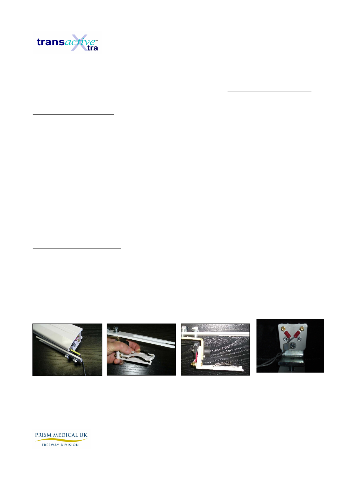
E3 - Repair/Replace Charging station and End Stop
IMPORTANT NOTE:
There are no serviceable parts in the Transactive-Xtra transformer. Use
extreme caution when performing internal servicing on the hoist. Ensure that the charger has
been disconnected from the power supply before starting.
REPAIR Charging station
1. The Charging station consists of the end stop components and the charging spring clips. If it
has been determined that the hoist is no longer charging because there is poor contact with
the charge strips, an adjustment can be made.
2. Remove the charging station from the track.
3. While holding the end stop gently pull up on the charge strips and bend to desired tension.
4. If too much tension is generated, the hoist will not be able to be driven out of the charging
station. Adjust the tension so that hoist can be driven in and out of the charging station.
5. With the manual traverse, there is a tendency to pull the hoist into the charging station at an
angle. This can cause one of the charger strips to lose tension. Please explain to client that
the hoist should be placed on the charger gently.
REPLACE Charging station
1. Should the charger strips bend and snap, a new charging station needs to be installed.
Remove the old station and disconnect the charger wires.
2. Reconnect the charger wires to the new charging station.
3. Replace the charging station and tighten bolts. Adjust tension as above.
Disconnect End stop
Gently bend strip
Correct positioning
Connections

Technical manual August 2009
Rev: 01/08/09 Page:
20
E4 - Repair Charging beak Contact Strips and Wire Harness (LED)
IMPORTANT NOTE:
Use extreme caution when performing internal servicing on the hoist.
Ensure that the battery has been disconnected before starting.
1. The original copper charger contact strips can become corroded in very humid and acidic
environments such as pools and spas. These have been replaced with stainless steel strips
on the newer hoist design.
2. Ensure that the RED battery lead has been disconnected.
3. Remove 4 screws in charging beak on trolley to detach the old strips.
4. Attach the new stainless steel strips. Ensure that the ring terminals on the wire harness are
centered under the screw holes.
5. If the Wire Harness requires replacement, cut cable tie and remove.
6. Disconnect the charger harness from the PCB and replace with new harness.
7. Reconnect the cable tie and ensure harness does not conflict with movement along the
track.
8. Test system to ensure that charging is occurring.
When attaching screws take care not to over tighten screws as you may strip the plastic thread.
Unscrew 4 screws Replace charger strips Red wire on left
Table of contents
Other Prism Medical UK Medical Equipment manuals

Prism Medical UK
Prism Medical UK A320B User manual

Prism Medical UK
Prism Medical UK Transactive Xtra User manual

Prism Medical UK
Prism Medical UK FREEWAY SA160 User manual

Prism Medical UK
Prism Medical UK Dual Access Sling Child User manual

Prism Medical UK
Prism Medical UK Easy Fit User manual

Prism Medical UK
Prism Medical UK SA160C User manual

Prism Medical UK
Prism Medical UK A-205 User manual

Prism Medical UK
Prism Medical UK Hammock Sling Child User manual


