Prism Medical FREEWAY SA160C mini User manual
User Manual
SA160C mini

Contents
1.0 Safety Instructions and Warnings
1.1 Caution .......................... 3
1.1 Symbols used ..................... 4
1.2 Contraindications ................. 5
1.3 Intended use...................... 5
2.0 Components/Key Parts ............... 6
3.0 Assembly ............................
3.1 Unpacking ....................... 7
3.2 Electrical connections ............. 7
4.0 Final Inspection......................8
5.0 Stand aid Operating Instructions
5.1 Manoeuvring the stand aid ......... 9
5.2 Stand aid leg opening adjustment ... 10
5.3 Raising and lowering the li arm.... 10
5.4 Emergency stop button ............ 10
5.5 Emergency lowering of the li arm .. 11
5.6 Handset operation ................ 12
5.7 Battery pack ...................... 13
5.7 Knee pad adjustment .............. 14
5.7 Carry bar reach adjustment......... 14
5.7 Removing the footplate ............ 15
5.7 General operation ................. 16
6.0 Stand aid Safety Advice
6.1 Caution .......................... 17
6.2 Daily checks...................... 19
7.0 Technical Specication
7.1 Dimensions ...................... 20
7.2 Sound levels ...................... 21
7.3 Electrical specications ............ 21
7.4 Standards applied ................. 22
8.0 Care & Maintenance
8.1 Troubleshooting .................. 23
8.2 Maintenance ..................... 24
8.3 Cleaning ......................... 26
9.0 Test Certicate.......................30
10.0 Service Record .......................31
2

1.0 Safety Instructions and Warnings
1.1 Caution
Do not attempt to use this equipment without rst
understanding the contents of this manual.
3
e stand aid can easily be
operated by one person.
To ensure the safe operation of
your stand aid, carefully read
this entire manual, and ensure
its contents are completely
understood before use.
e stand aid is designed to be
used in conjunction with slings
and accessories. Please refer
to any user guides supplied
with these components while
reviewing this manual.
Should any questions arise
from reviewing this manual
contact your local authorised
representative.
Failure to comply with warnings
in this manual may result in;
injury to the operator and/or
client and/or damage to the stand
aid or related components.
Store this manual with the
documents included with the
stand aid and sling(s).
Contents of this manual are
subject to change without prior
written notice.
Ensure you are aware of the
sling manufacturer’s tting
instructions.
WAR N ING
Do not use a clip t sling on a hook designed specically for loop
tting slings.

1.0 Safety Instructions and Warnings
1.1 Symbols used
4
Caution - consult instructions for use
Caution - consult instructions for use
Manufacturer
Please observe local laws on recycling
Two-person li may be required
Refer to user manual
Date of manufacture
Serial number
Temperature range
Humidity range

1.0 Safety Instructions and Warnings
1.2 Contraindications
5
ere are no known
‘contraindications’ associated
with the usage of the stand aid
and its accessories, provided they
are used a per manufacturer’s
recommendations and guidelines.
However, it is recommended
that a client specic assessment
is completed by a trained and
knowledgeable health care
professional to determine the
method of transfer.
e manufacturer does not
recommend a required number
of caregivers for the use of our
products.
is information and
recommendation can only be
provided aer a thorough, case
specic, assessment, as there are
many factors that can inuence
these decisions.
1.3 Intended use
e stand aid is a liing aid used
by trained personnel. e stand
aid is used to assist individuals
from sitting to standing,
transporting and walking
with minimal strain or risk to
the caregiver, while providing
complete safety, dignity and
comfort to the client.
e stand aid is one of two
components that makes this
possible.
e other component, the belt/
sling, is a specially designed
fabric accessory that attaches to
the stand aid by means of hooks
and straps, and holds the client
during the li/transfer.
Please refer to the user guides
supplied with the belt/sling and
reference them while reviewing
this manual.
e functions of raising and
lowering the liing arm, and
opening and closing of the legs on
the stand aid, are accomplished
by pressing buttons on the hand
control. e hand control is
attached to the stand aid.
e stand aid is intended for patients below 160kg.
If the safe working load of the stand aid is exceeded,
the overlaod feature will be activated.
WA R NING
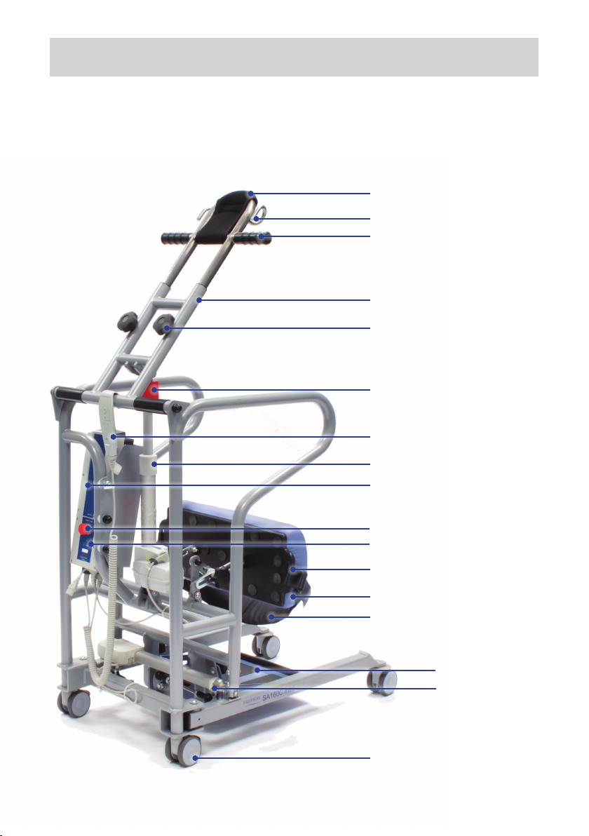
2.0 Components/Key Parts
Please familiarise yourself with the components of
the stand aid by referring to the diagram below:
6
Belt/sling hooks
User handle
Liing arm
Hand control
Actuator
Battery
Emergency stop button
Emergency lowering button
Adjustable knee pad
Leg strap anchor loop
Footplate
Actuator
Rear brake castors
Reach adjustment
Manual emergency
lowering
Optional leg strap
Optional body protector

3.0 Assembly
3.1 Unpacking
7
e stand aid has been delivered to you as a complete unit wih no
assembly required. It is suggested that the battery be fully charged
before rst use. To charge the battery: connect the charger unit to the
control box and mains, ensure that the Emergency stop button is in
the out position and allow the battery to recharge (the battery cannot
be over-charged).
is user manual should be kept safe for future reference.
Take care whilst removing the stand aid as the unit weight is 40kg
and may need two people to remove from its packaging.
WA R NING
WA R NING
2-person li recommended.
a. Remove the straps from the stand aid
outer packaging.
b. Li the cardboard lid from the box.
c. Carefully li the box sides from the
cardbaord base (revealing the stand aid).
d. With care li the stand aid from the
cardboard base (a two person li
is recommended).
3.4 Electrical connections
All cables should arrive securely attached to the control box when the
stand aid is unboxed.
Conrm all cables are secure before operating the stand aid.
WA R NING

4.0 Final Inspection
Before rst operation of the stand aid:
• Conrm all cables are located and secure.
• Ensure the red emergency stop button on the control box is in the
out position (rotate clockwise to release if required).
• Press the up button on the handset and conrm the actuator
raises the li arm.
• Press the down button on the handset and conrm the actuator
lowers the li arm.
• Press the button on the handset to operate the leg opening and
conrm the actuator moves the legs outward.
• Press the button on the handset to operate the leg closing and
conrm the actuator moves the legs inward.
• Press the red emergency stop button on the control box and check
that actuators do not operate until the button is returned to the
out position.
• Check the emergency lowering function, both mechanical and
electrical, work properly.
• Check the rear wheel brakes work properly.
• Check the battery pack is fully charged.
Your stand aid is now ready to use.
8

5.0 Stand aid Operating Instructions
5.1 Manoeuvring the stand aid
To move the stand aid forward, hold onto
the handle bar (shown in Fig.1)
and push forward.
When turning the stand aid, use both
hands on the handle. Alternatively, it
is possible to rotate the stand aid by
applying the brake to a single rear caster
and rotating the stand aid about the
braked caster. is movement should be
performed with a smooth, slow action.
e SA160C mini stand aid has two rear
casters with brake.
e rear casters can be braked for rotation
(by applying a single brake), lateral
movement, and parking. To apply the
brake, press the brake pedal down with
your foot (as shown in Fig.2). To release the
brake, press the raised pedal towards the
wheel (as shown in Fig.3).
9
If the footplate is not being used, then the brakes must be applied
prior to standing.
WA R NING
Do not stand on the actuator, or use the
actuator to push the stand aid.
WA R NING
Fig. 2
Fig. 3
Fig. 1
5.0 Stand aid Operating Instructions
10
5.2 Stand aid leg opening adjustment
e legs of the SA160C mini stand aid are electrically operated for
opening and closing to adjust the base width. e legs can be opened
to enable access around arm chairs or wheel chairs. When relocating
the stand aid, manoeuvring through narrow doorways or passages,
the stand aid legs should be in the closed position.
Leg adjustment is achieved by pressing
appropriate buttons on the hand control.
e legs’ motion will be stopped whenever
the hand control button is released.
5.3 Raising and lowering the li arm
e up and down movement of the li arm
on the SA160C mini stand aid is achieved
by a powerful electric actuator which is
controlled by hand control. e hand
control has two buttons with directional
arrows up and down. e actuator stops
automatically at the limit of travel in both
directions.
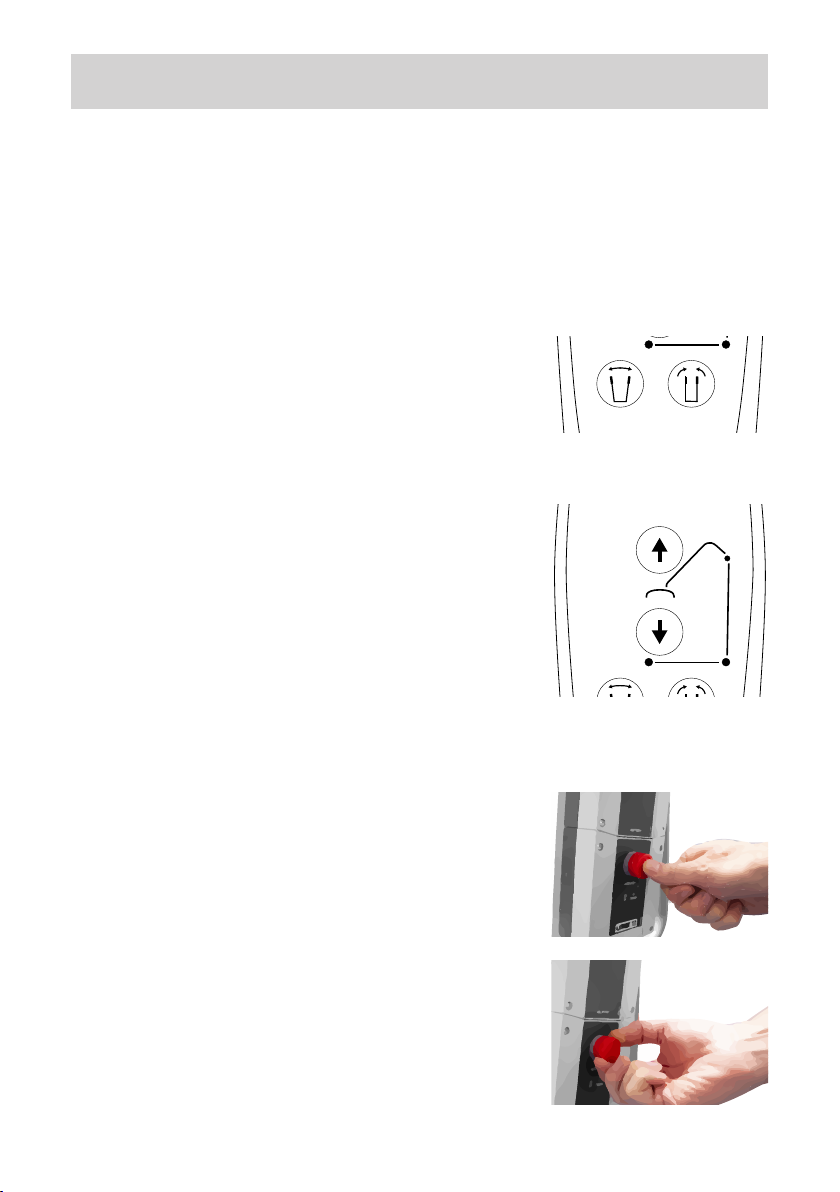
5.4 Emergency stop button
e SA160C mini stand aid is tted with an
Emergency Stop button.
Push the Emergency Stop button (as
shown in Fig.4) to cut all power on the
stand aid (an audible beep will be heard
if the emergency button is pressed during
operation of the li arm or leg opening).
To resume power, release the emergency
stop button by turning in a clockwise
direction (indicated by arrows on the
Emergency Stop button) as shown in Fig.5.
Fig. 4
Fig. 5

5.0 Stand aid Operating Instructions
11
5.5 Emergency lowering of the li arm
5.5.1 Electrical emergency lowering
e stand aid li arm can be lowered by
pushing the emergency lowering button on
the control box with a suitable object, such
as a pen nib or pencil (as shown in Fig.6).
5.5.2 Mechanical emergency lowering
In case of power failure, it is possible to
mechanically lower a patient placed in
SA160C mini stand aid.
Turn the manual lowering handle in a
clockwise direction (as shown in Fig.7)
to lower the li arm until the li arm
reaches a safe position.
e manual emergency lowering system should be used only if the
lowering procedures described in the previous section of the manual
do not work. Should you have any concerns or questions contact
your local authorized Prism Medical Representative.
WA R NING
Fig. 6
Fig. 7
5.0 Stand aid Operating Instructions
12
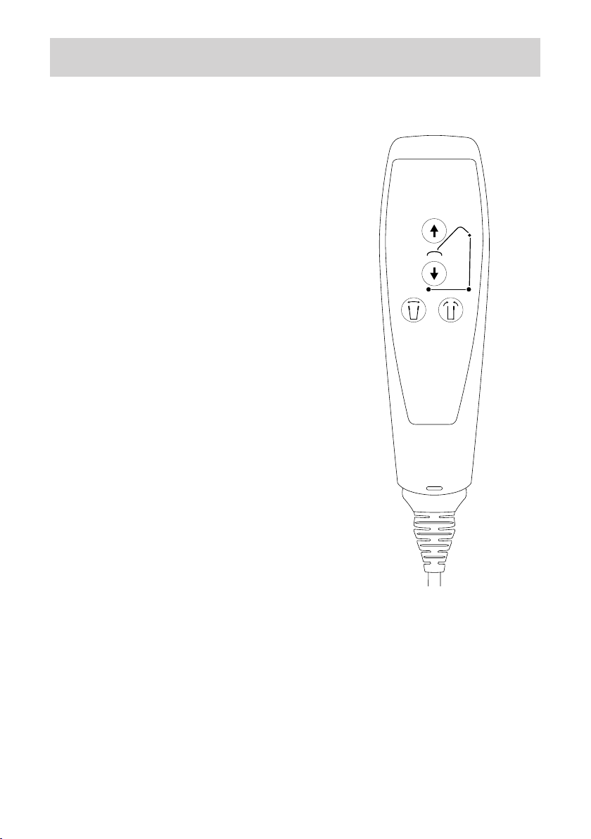
5.6 Handset operation
e Hand Control has four
functions: up/down
and legs in/out.
Press down on each symbol to
operate the desired function. It is
not possible to use two functions
at the same time. Once the stand
aid has reached the extent of its
travel in a given direction, an
audible beep will sound.
e handset is attached to the
control box via a exible, coiled
cable that is secured in place
with a friction-t plug. e
coiled cable is designed to give
the greatest number of options
for carer positioning without
having a trailing cable around
the patient. e handset also
incorporates a hook which gives
the carer exibility whist moving/
positioning the patient. Clear and
easy to understand labelling of
the buttons enable ease of use for
the care giver. Fig. 8

5.0 Stand aid Operating Instructions
5.7 Battery pack
e battery pack is protected from full discharge by a low voltage
alarm and illuminated LED. e alarm will sound or LED illuminate
when the battery needs recharging. Complete the li and place the
battery on charge.
13
• Keep the battery pack fully charged.
• e battery pack should never be allowed to run completely at.
• e battery pack should never be stored for long periods of time
without a regular charge.
5.8.1 Charging the battery pack
e battery pack can be recharged via
mains lead (terminated with a gure of
eight plug), or can be unclipped from the
control box (see Fig. 9 and 10) and charged
via an optional external charger (available
separately).
a. Fit the mains lead gure of eight plug
into charger link cable (see Fig.11).
b. Plug the 3-pin mains plug into a suitable
mains outlet and switch the mains supply on.
Note: e red Emergency Stop button has
to be out for the battery pack to charge.
c. Charging is automatic and will
normally take eight to twelve hours to fully
charge (from completely discharged state).
You cannot overcharge the battery pack if
le for longer periods of time.
d. To return the stand aid to use, switch o
the mains supply. Remove the gure of eight
plug from the socket at the base of the control
box. e stand aid is now ready for use.
WA R NING
Fig. 11
Fig. 9
Fig. 10

5.0 Stand aid Operating Instructions
14
5.8 Knee pad adjustment
e knee pad can be adjusted for reach,
height and angle. Adjustment is made by
loosening the two star knobs either side
of the knee pad (as shown in Fig. 12) and
position the knee pad (as shown in Fig. 13).
Once the knee pad has been positioned
correctly tighten the star knobs and ensure
the knee pad is secure.
e knee pad includes loops for the
optional knee strap kit. e strap should
be passed through the loop at either side of
the pad (as shown in Fig. 14) and fastened
5.9 Carry bar reach adjustment
e carry bar reach adjustment is done by
loosening the two star knobs by three turns
anti-clockwise (as shown in Fig. 15). Once
the carry bar has been positioned correctly
(Fig. 16), tighten the star knobs and ensure
it is secure.
Fig. 12
Fig. 13
Fig. 15
Fig. 16
Ensure the adjustment star knobs are
tight on the knee pad to prevent knee
support movement during use.
WA R NING
Do not attempt to adjust the carry bar
reach position while the li arm is in use.
WA R NING
Ensure the adjustment star knobs are tight
on the carry bar adjustment before use.
WA R NING
Fig. 14
5.0 Stand aid Operating Instructions
15
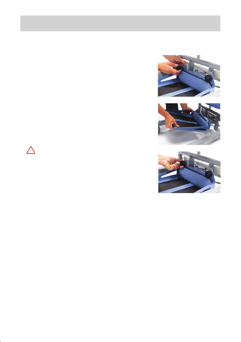
5.10 Removing the footplate
e footplate can be removed by loosening
and removing the two star knobs (as shown
in Fig. 17).
With the two star knobs and bolts removed
carefully li the foot plate from the frame
(as shown in Fig. 18). It is recomended to ret
the star knobs to the frame for future use.
When re-attaching the foot plate,
ensure it is securely tted before use
(as shown in Fig. 19).
Fig. 17
Fig. 18
When using the equipment to assist a
person to stand onto the oor (with the
footplate removed), the brakes must be
applied.
WA R NING
Fig. 19
5.11 General operation
Ensure you select the correct sling size for the person being transferred.
e sling should be tted around the person’s stomach/lower back and
not around the chest.
Push the SA160C towards the person and apply the brakes.
Adjust the position of the carry bar:
• Unscrew the handles e turns anticlockwise
• Adjust the carry bar to the required position
• Rotate handles clockwise to tighten the carry bar in position
5.0 Stand aid Operating Instructions
16
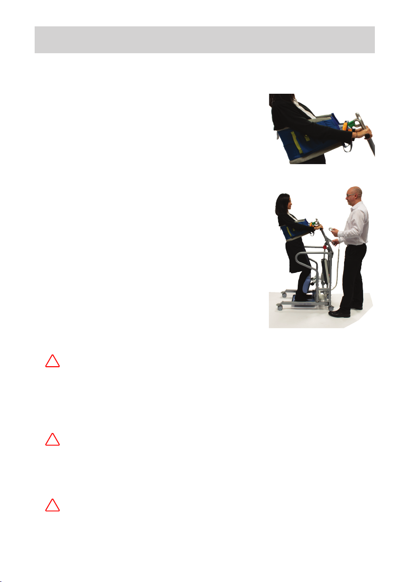
5.11 General operation (continued)
Attach the relevant slings loops to the
hooks of the carry bar (Fig. 20).
Use the up function on the handset to
raise the person into a standing position
(as shown in Fig. 21).
If you are not using the footplate the
brakes must be applied prior to standing.
Fig. 20
Fig. 21
e stand aid features a safety cut-o. Should the li arm encounter
an obstruction during lowering, an audible clicking noise will be
heard. To re-activate, remove the obstruction and briey press the up
button on the hand control, the unit will then function as normal.
WA R NING
When the liing arm goes beyond vertical, the liing arm will
require gentle pressure (towards the user), to activate the downward
movement as normal.
WA R NING
When not in use, remove the sling from the stand aid to reduce the
potential for entrapment or strangulation. Ensure the emergency
stop button is pressed to avoid accidental activation.
WA R NING

6.0 Stand aid Safety Advice
6.1 Caution
17
Your stand aid is designed as a stand assist device.
Do not use it, or allow it to be used, for any other purpose.
Your stand aid has been manufactured and tested to exceed BS EN
10535:2006. is does not mean that it can be used without care.
All operators should have read the operating instructions and
appreciate this Caution section.
When not in use, remove the belt/sling from the stand aid to reduce
the potential for entrapment or strangulation. Especially in areas
where children may be present.
WA R NING
WA R NING
CAUTION: YOUR Stand aid
Is less stable on sloping surfaces. A 5 degree slope is the maximum
permitted and then only with great care.
Is less stable when the load is at maximum height.
Is dangerous to the patient being carried when used with undue care
and attention or pushed at speed.

6.0 Stand aid Safety Advice
18
Please read and follow the safety precautions below. ese basic safety
precautions will help make liing operations easy and trouble free.
A LWAY S
Carry out the Daily Checks (detailed in section 6.2)
Conduct a risk assessment, including patient, stand aid
capacity and belt/sling suitability, prior to any liing operation
Ensure you have had basic training in moving and handling
before using the stand aid
Familiarise yourself with the stand aid controls
and safety features
Manoeuvre the stand aid with the handle provided
Fit the belt/sling in accordance to the user manual
Carry out lis in accordance with this user manual
Apply the brakes when parking the stand aid
NEVER
Push a loaded stand aid at a speed exceeding a slow walking pace
Manoeuvre the stand aid using the li arm or patient
Use a sling unless recommended for use with this stand aid
Push the stand aid over uneven or rough ground
Bump the stand aid down steps
Depress the carry bar reach adjustment handle during liing
Expose actuators to cleaning without all cables being tted
Allow water to enter the handset or control box
Use the stand aid outdoors
Use a frayed or damaged belt/sling
Charge the stand aid in a bathroom or shower

6.0 Stand aid Safety Advice
6.2 Daily checks
e following checks are those recommended by Prism Medical UK
and are supplementary to requirements that may be applicable for
current Liing and Handling and other Health and Safety regulations
such as e Liing Operations and Liing Equipment Regulations
1998 which may have additional requirements to those set out below:
19
CHECK
e legs open and close correctly.
e stand aid moves freely on its castors.
e carry bar securely locks in position.
e sling hooks on the carry bar are free from excessive wear.
e hand control lowers and raises the li arm satisfactorily.
e operation of the emergency stop button.
e stand aid is o charge before use and all leads are fully
engaged into their sockets.
e stand aid is charged to a satisfactory level of use - raise and
lower the stand aid by operating the handset. If the stand aid
makes a bleeping sound do not use as the stand aid needs to be
charged.
e belt/sling for fraying or damage.
Do not use with any signs of fraying, tears or other damage to
the straps or body of the belt/sling.
e footplate is clean, dry and free of any foreign particles.
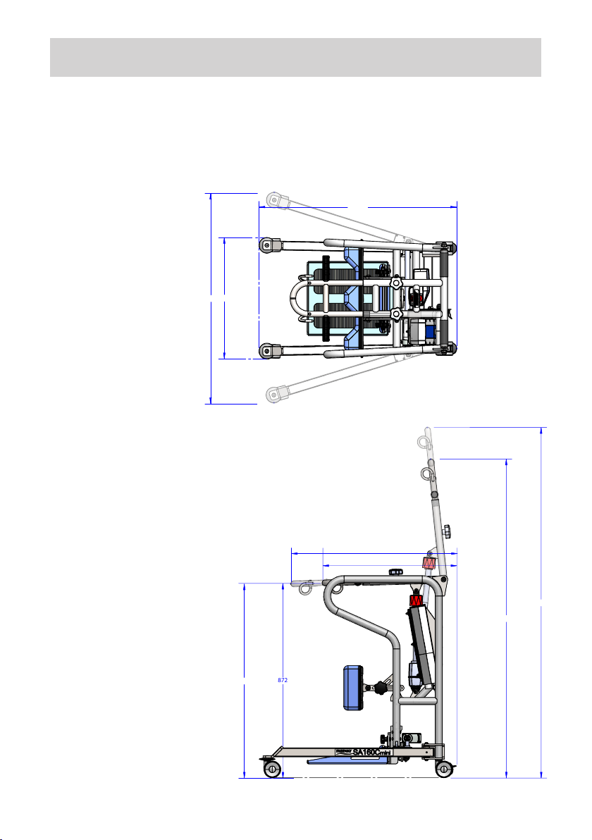
7.0 Technical Specification
7.1 Dimensions
Total weight: 45kg Actuator thrust: 8,000N
20
872
600
1570
1428
743
869
541
881.50
939
Table of contents
Other Prism Medical Medical Equipment manuals


Popular Medical Equipment manuals by other brands

Bittium
Bittium OmegaSnap 3-CH ECG Electrode quick guide

baxter
baxter 6060 2M9832 Operator's manual

LED Technologies, Inc.
LED Technologies, Inc. DPLCOMWP quick start guide

Olympus
Olympus EU-ME2 Quick reference guide

bort medical
bort medical 104 690 quick guide

EASTMAN
EASTMAN Kodak RP X-Omat Processor M6B manual


Ivy Biomedical Systems
Ivy Biomedical Systems 2000 Operator's and service manual

Orliman
Orliman DS03 Use and maintenance instructions

Plinth 2000
Plinth 2000 93CT Service manual

ConvaQuip
ConvaQuip ConvaLift CL600E owner's manual

Civco
Civco C-Qual reference guide

Richard Wolf
Richard Wolf ENDOLIGHT LED 2.2 instruction manual