EASTMAN Kodak RP X-Omat Processor M6B User manual

Publication No. 1C7070
May 1994
Supersedes 2B6835
July 1993
635883
April 1988
SITE SPECIFICATIONS
for the
Kodak
RP
X-Omat
Processor, Model M6B
H048_0086DA
Eastman Kodak Company, 1994

PLEASE NOTE
The information contained herein is based on the experience and knowledge relating to the subject matter gained by
Eastman Kodak Company prior to publication.
No patent license is granted by this information.
Eastman Kodak Company reserves the right to change this information without notice, and makes no warranty, express
or implied, with respect to this information. Kodak shall not be liable for any loss or damage, including consequential or
special damages, resulting from the use of this information, even if loss or damage is caused by Kodak’s negligence or
other fault.
To avoid hazardous conditions, keep floors and floor coverings around your
Kodak X-Omat
Processor and associated drains clean and dry at all times. Any accumulation of fluids from
mixing tanks, drain lines, etc., should be cleaned up immediately. In the event of an accumulation
of the liquid due to backup, overflow, or other malfunction of the drain associated with your
Kodak
X-Omat
Processor, call a plumber or other contractor to correct any problem with your drain.
Kodak accepts no responsibility or liability whatsoever for the serviceability of any drain connected
to or associated with a
Kodak X-Omat
Processor. Such drains are the sole responsibility of the
customer.
Possible damage from electrostatic discharge.
2 1C7070

Table of Contents
Description Page
Introduction.............................................................................................................................................................5
Dimensions and Weights......................................................................................................................................6
Electrical Requirements ........................................................................................................................................7
Basic Requirements..........................................................................................................................................7
Standard Service Options.................................................................................................................................7
Water and Drain Requirements............................................................................................................................8
Water Supply ....................................................................................................................................................8
Drain..................................................................................................................................................................8
Environmental Requirements ...............................................................................................................................9
Room Ambient Temperature ............................................................................................................................9
Air and Heat......................................................................................................................................................9
Diagrams...............................................................................................................................................................11
Center of Gravity..................................................................................................................................................21
1C7070 3

BLANK PAGE
4 1C7070

Introduction
This publication is part of a series of instruction books that provides technical support information on the
KODAK
RP
X-OMAT Processor, Model M6B. For the ease of referencing and reordering the other publications,
the following tables provide the part numbers for each of the publications.
Publications for M6B Processors - Serial Numbers 15,000 and Above
Complete Operator Installation Service
Binder Manual Site Specs Instructions Manual Parts List
Publication 246630 1C7061 1C7070 246626 246628 246629
Part No.
Publications for M6B Processors - Serial Numbers 10,000 to 14,999
Complete Operator Installation Service
Binder Manual Site Specs Instructions Manual Parts List
Publication 635881 1C7061 1C7070 635884 635885 635882
Part No.
Publications for M6B Processors - Serial Numbers Below 10,000
Complete Operator Installation Service
Binder Manual Site Specs Instructions Manual Parts List
Publication Not 1C7061 1C7070 635812 635828 635860
Part No. Available
It is recommended that these publications be kept in the binder provided. If an individual document gets
misplaced or destroyed, reorder a copy from your Eastman Kodak Representative.
1C7070 5

Dimensions and Weights
Table 1 Dimensions and Weight of the Processor
Description Crated Uncrated
Length 71.1 cm (28 in.) 63.5 cm (25 in.) Without feed tray
(Includes knobs and fittings.)
97.8 cm (38.5 in.) With feed tray
(Includes dryer knob.)
Width 90.2 cm (35.5 in.) 76.2 cm (30 in.)
Height 152.4 cm (60 in.) 123.2 cm (48.5 in.)
Weight (Tanks Empty) 223.2 kg (492 lb) 201 kg (442 lb)
Weight (Tanks Full) Not Applicable 235 kg (519 lb)
Approximate Solution Height Not Applicable 107.2 cm (42.5 in.)
from the Base of the
Processor
Table 2 Maintenance and Operation
Access Requirements
Description Recommendation
Dryer End of Processor 91.4 cm (36 in.)
Feed End of Processor 91.4 cm (36 in.)
Drive Side of Processor 91.4 cm (36 in.)
Non-Drive Side of Processor 91.4 cm (36 in.)
Top of Processor 91.4 cm (36 in.)
6 1C7070

Electrical Requirements
IMPORTANT
Basic Requirements
In addition, all electrical services, including earth ground, must comply
with local and national electrical codes.
• 30 A, single-phase, 208/220, 3-wire, earth ground
required.
• Main Power Disconnect (wall-mounted, not furnished)
The main power disconnect switch must consist of a minimum 2-pole thermo-magnetic
circuit breaker with solid neutral and common trip, or a fused disconnect switch. This
switch must be:
• located on a wall adjacent to the processor in the lighted area
• easily accessible from the processor site
• visible from the processor site.
IMPORTANT
Standard Service
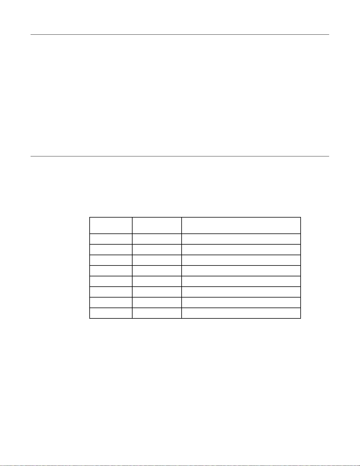
Options In addition, all electrical services, including earth ground, must comply
with local and national electrical codes.
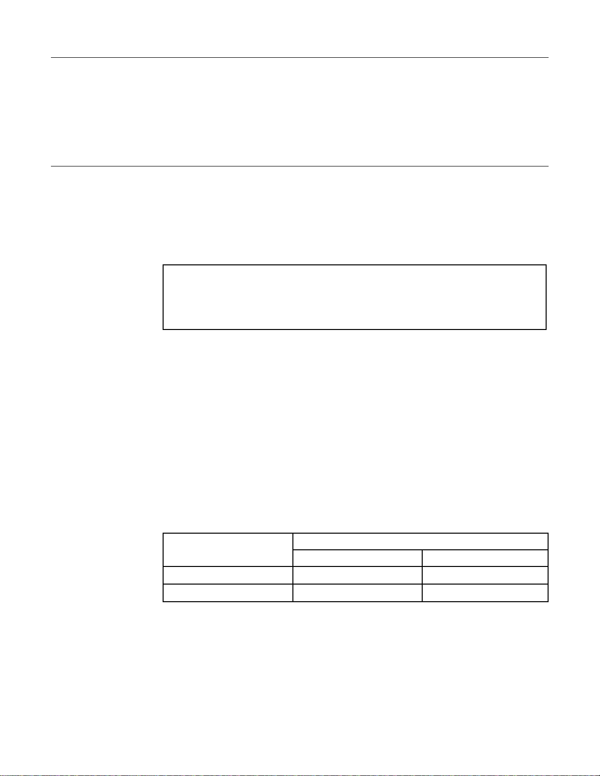
Table 3 Service Options
Voltage Frequency Service
Volts Hz
100/200 50/60 Single-phase, 3-wire
120/208 60 Three-phase*, 3-wire, Wye
120/240 60 Single-phase, 3-wire
127/220 50 Three-phase*, 3-wire, Wye
220/380 50 Three-phase*, 3-wire, Wye
240/415 50 Three-phase*, 3-wire, Wye
220 50/60 Single-phase, 2-wire
240 50/60 Single-phase, 2-wire
*L1, L2, and Neutral used in this configuration are sometimes referred to
as Single-Phase connections.
1C7070 7

Water and Drain Requirements
a. Processor Supply
Water Supply (1) Temperature: 4° to 29.4°C (40° to 85°F)
NOTE
If the upper limit of the room ambient or the water supply temperature to the processor is
exceeded, the developer temperature may not be controlled correctly. A water chiller may be
required.
(2) Pressure: 172.35 to 448.11 kPa (25 to 65 psi). Install regulator if required.
(3) Volume: Controlled within the processor to 5.7 L/min (1.5 gal/min).
(4) Filtration: A 50-micron filter is required, but it is not supplied with the
processor.
b. Water service must comply with local codes.
c. Tempered water service is suggested for processor cleaning and for mixing
chemicals manually.
d. A molded adapter and washer are provided to adapt the processor garden hose
fitting to the 1/2 in. NPT (male).
Drain
• Drains must be made of chemically resistant, non-corrosive material.
Use PVC or the equivalent.
• The drain must have a minimum diameter of 7.6 cm (3 in.) and be free of
obstruction.
• Drain service must comply with all local codes.
• Locate the drain within 1.5 m (60 in.) of the processor.
• The drain line should slope gradually downward to the floor drain.
Capacity: 15 L/min (4 gal/min).
Connection: Open drain; avoid solid connection.
8 1C7070

Environmental Requirements
• Temperature: 15° to 30°C (59° to 86°F)
Room Ambient
Temperature • Humidity: 15% to 76%
NOTE
If the upper limit of the room ambient or the water supply temperature to
the processor is exceeded, the developer temperature may not be
controlled correctly. A water chiller may be required.
a. Air Exhaust (full load)
Air and Heat (1) Volume: 1.9 m3/min (65 ft3/min)
(2) Temperature: 66°C (150°F) maximum
(3) Moisture>300 gr/min or 121 gr/kg (55 gr/lb) of air
b. Heat load to room: 4220 kJ/hr (4000 Btu/hr)
To protect the processor and equipment directly interfaced with the
processor, the dryer must be vented according to the following
specifications. Failure to properly vent the dryer exhaust can cause
corrosion within the processor and interfaced equipment. In addition, the
probability of processor-related film artifacts is increased.
[1] The processor exhaust duct must be connected to the building exhaust ducting
system. Disposal of effluent air must comply with prevailing environmental
codes.
[2] The following table should be used to determine the proper amount of negative
air within the duct at the end to be connected to the processor. To prevent
venturi effect at the duct opening, all measurements should be made at a point
30.5 cm (12 in.) from the open end of the duct to be attached to the processor.
Compare the average reading with the table below.
Table 4 Static Pressures
Negative Static Pressure, (Water Head)
Duct Diameter MIN MAX
76 mm (3 in.) 0.76 mm (0.03 in.) 1.02 mm (0.04 in.)
102 mm (4 in.) 0.25 mm (0.01 in.) 0.51 mm (0.02 in.)
1C7070 9

[3] Measurement can be made using an Air Meter, available through Service Parts
Management as TL-2431. Measurement of negative air within flexible duct
hoses will be simplified with the use of a modified Chemical Replenisher Check
Tube P/N 592380, cut to a 30.5 cm (12 in.) straight line length, and connected
to the rubber hose supplied with the Air Meter. An alternative is to use a hose
support made from a straight piece of wire, such as a coat hanger, and tape
the rubber hose to it.
H048_0118BA
(12 in.)
30 cm
AIR FLOW
HOSE SUPPORT
CENTER CONNECTOR
AIR METER
TAPE (3 places)
MODIFIED J TUBE
RUBBER HOSE or
EXHAUST HOSE
H048_0118BCA
Figure 1 Measuring Negative Static Pressure
[4] If solid metal or rigid plastic ducting is attached to the processor in a manner
which would prevent easy removal, a small hole may be created at a point
approximately 30.5 cm (12 in.) from the processor vent connection. The ‘‘L’’
shaped metal tube provided with the Air Meter can then be inserted through the
opening. When measuring negative air, the tube tip opening should be pointed
in the direction of airflow away from the processor.
IMPORTANT
The processor must be turned off when making air measurements. The
Air Meter should be held in the vertical position to assure the greatest
accuracy. The meter tubing must not be kinked.
[5] It is most important that negative airflow in the processor exhaust duct remains
constant when the processor is in the run, standby, and shut-down modes.
When processors are installed in darkroom wall openings, it is most important that
darkroom air pressure exceeds the air pressure of the area surrounding the darkroom.
This is intended to prevent air cascading through the processor into the darkroom
area. Proper balancing of dark/lighted room air in addition to correct dryer venting will
not only maximize containment of chemical fumes and vapors within the processor and
its dryer exhausting system, but the incidence of film artifacts occurring in the
out-of-solution transport roller sections will be greatly reduced.
10 1C7070

Diagrams
H048_0085DA
H048_0085DCA
INTERFACE
JACK
SAFELIGHT/
ACCESSORY
RECEPTACLE
MAIN
CIRCUIT
BREAKER
FIXER
AUXILIARY
DRAIN
DEVELOPER
AUXILIARY
DRAIN
EXHAUST
FEED TRAY
and SHELF
WATER DRAIN VALVE
WASH OVERFLOW
and DRAIN
FIXER OVERFLOW
and DRAIN
DEVELOPER
OVERFLOW
and DRAIN
BUZZER
WATER INLET
U.S. GARDEN
HOSE CONNECTOR
FIXER DRAIN
VALVE
DEVELOPER
DRAIN VALVE
REPLENISHER TUBING
INLETS from REMOTE TANKS
AUXILIARY
CIRCUIT
BREAKERS
RUN SWITCH RUN SWITCH
Figure 2 Feed-End View of the Processor
1C7070 11

H048_0086DA
DISPLAY
PANEL
RECEIVING
BIN
TOP COVER
H048_0086DCA
Figure 3 Receiving-End View of the Processor
H048_0025BA
H048_0025BCC
DRYER
TEMPERTURE
CONTROL
DRYER INDICATOR
LAMP
DEVELOPER
TEMPERATURE
METER
DEVELOPER
INDICATOR
LAMP
FIXER
REPLENISHMENT
FLOAT
DEVELOPER
REPLENISHMENT
FLOAT
REPLENISHMENT
SWITCH
Figure 4 Display Panel on Receiving-End of the Processor
12 1C7070

H048_0121EC
(4.50 in.)
114 mm
38 mm (1.50 in.)
51 mm
(2.00 in.)
406 mm (16.00 in.)
(2.00 in.)
51 mm
(14.50 in)
381 mm
(19.25 in.)
489 mm
(21.50 in.)
546 mm
(23.25 in.)
590 mm
63 mm (2.50 in.)
248 mm (9.75 in.)
Leveling Feet
Center To Center Distance Of
(27.00 in)
686 mm
121 mm (4.75 in.)
57 mm (2.25 in.)
(13.25 in.)
425 mm
(14.25 in.)
362 mm
(48.50 in.)
1232 mm
57 mm (2.25 in.)
(7.75 in.)
196 mm
(3.12 in.)
77 mm
(3.25 in.)
83 mm
(7.75 in.)
196 mm
762 mm (30.00 in.)
Figure 5 Feed-End Dimensions of the Processor
1C7070 13

H048_0120DA
PLATFORM
FINISHED FLOOR
COLD WATER
SUPPLY
HOT WATER
SUPPLY Mixing faucet
with hose bib
H048_0120DCA
Figure 6 Replenisher Tanks
Table 5 Dimensions for Replenisher Tanks
DESCRIPTION DIMENSION 14 GAL 30 GAL 55 GAL
Max Platform Height ‘‘A’’ Fig. 14 48.3 cm (19 in.) 35.6 cm (14 in.) 15.2 cm (6 in.)
Tank Diameter ‘‘B’’ Fig. 14 43.2 cm (17 in.) 55.9 cm (22 in.) 61.0 cm (24 in.)
Tank Height ‘‘C’’ Fig. 14 58.4 cm (23 in.) 70.5 cm (27.75 in.) 90.8 cm (35.75 in.)
External Replenishment ‘‘D’’ x ‘‘E’’ 61.0 X 127.0 cm 61.0 x 152.4 cm 66.0 x 172.7 cm
Tank Area (MIN) Fig. 15 (24 X 50 in.) (24 x 60 in.) (26 x 68 in.)
14 1C7070

H108_0006DA
Figure 7 Suggested Room Layout and Drain Locations
Table 6 Maintenance and Operation Access Requirements
Description Recommendation
Receiving-End of Processor 91.4 cm (36 in.)
Feed-End of Processor 91.4 cm (36 in.)
Drive-Side of Processor 91.4 cm (36 in.)
Non-Drive Side of Processor 91.4 cm (36 in.)
Top of Processor 91.4 cm (36 in.)
1C7070 15

57.2 cm
(22.5 in.)
ROOMLIGHT
AREA
SAFELIGHT FIXTURE
(not furnished)
connect to safelight outlet of
processor (for visual feed indicator)
DARKROOM
AREA 121.9 cm
(48.0 in.)
minimum
38.1 cm
(15.0 in.)
5.1 cm
(2.0 in.)
112.1 cm
(44 in.)
7.6 cm
(3.0 in.)
LIGHT-TIGHT GASKET
compress to approx.
1.0 cm (.38 in.)
upon installation
ENTRANCE
ROLLER
ASSEMBLY
DRYER
EXIT
ROLLERS
50.8 cm
(20.0 in.)
49.5 cm
(19.5 in.)
Center to Center
Distance of Leveling Feet
3.8 cm
(1.5 in.) FLOOR
H048_0090DA
Figure 8 Side Dimensions
16 1C7070

H048_0089DA
H108_0009DAA
Figure 9 Electrical and Water Connections
NOTE
• Pass service through the wall to the feed-end of the processor in the darkroom. Service
controls may be located on either side of the processor for easy accessibility.
• See the Table on page 18.
1C7070 17

Table 7 Electrical and Water Connections, Continued
A Service Hose - suggested length to reach the Processor and Replenisher Tanks.
B⁄
12in. NPT Check Valve
C Kodak Thermostatic Mixing Valve ⁄
12in. NPT available from Eastman Kodak Company,
Part No. 467621. Not supplied with the Processor.
IMPORTANT
A mixing valve is not required for the processor if incoming water temperature is between
4° and 29.4°C (40° and 85°F).
D Shutoff Valves ⁄
12in. NPT. Two additional required. Available from Eastman Kodak Company,
Part No. 459981. Not supplied with the Processor.
E Cold Water Supply ⁄
12in. NPT
F 30 AMP - 2 POLE, Thermo-magnetic Circuit Breaker. Locate safe distance from water service.
Not supplied with the Processor.
G Shutoff Valves ⁄
12in. NPT. Two additional required. Available from Eastman Kodak Company,
Part No. 459981.
H Hot and Cold Water Supply ⁄
12in. NPT.
I⁄
12in. NPT Union. Locate as close to the Processor as possible.
NOTE
• The processor is UL listed, CSA certified. Specifications are subject to change without notice.
• Follow local electrical and plumbing codes.
18 1C7070

H048_0005DA
BOLT
WASHER
ANCHOR
FLOOR
CUP
BRACKET
H048_0005DCA
Figure 10 New Wall Installation
AIf the wall around the opening is straight and exactly perpendicular to the floor, this panel may not be
necessary. The wall opening dimensions should match the inside dimensions of the panel opening.
BMake sure that the vertical dimension of 48 ±1/16 in. for the wall opening is measured from the finished
floor.
1C7070 19

H048_0091AA
H048_0091ACA
Inlets for Replenishment Tubing
Figure 11 Inlets for Replenisher Tubing
H048_0006DA
Figure 12 Alternate Inlets for Replenisher Tubing
20 1C7070
Table of contents
Other EASTMAN Medical Equipment manuals