Richard Wolf ENDOLIGHT LED 2.2 User manual

GA-A
GA-AGA-A
GA-A 307
307307
307
/
en
/
//
/
2015-06 V1.0
/ PDG 00-0000
ENDOLIGHT LED 2.2
51640x1
Instruction
InstructionInstruction
Instruction Manual
ManualManual
Manual

0
GA-A 307
Important
ImportantImportant
Important general
generalgeneral
general notes
notesnotes
notes and
andand
and instructions
instructionsinstructions
instructions
Make sure that this product is used only as intended and described in this instruction manual and by adequately trained
and qualified medical personnel, Maintenance and repair must be carried out by authorized experts.
Use the product only in the combinations and with the accessories and spare parts specified in this instruction manual.
Use other combinations, accessories and replacement parts only if they are expressly intended for the planned appli
cation and if the performance characteristics and safety requirements are met. The product must not be altered in any
way.
Reprocess the product in accordance with the manual before every use and before return shipment to protect the pa
tient, user and third parties.
This manual is an integral part of the product and must be stored in such a way that it is accessible at any time during
its entire life cycle. This manual must be passed on to any subsequent owner or user.
Immediately upon receipt, check the product and its accessories for completeness and possible damage. Should the
shipment give rise to complaints, please inform the manufacturer or supplier immediately.
Subject
SubjectSubject
Subject to
toto
to technical
technicaltechnical
technical changes!
changes!changes!
changes!
Due to ongoing developments the illustrations and technical data may deviate slightly.
Safety
SafetySafety
Safety instructions
instructionsinstructions
instructions and
andand
and levels
levelslevels
levels of
ofof
of danger
dangerdanger
danger
Symbol
SymbolSymbol
Symbol Level
LevelLevel
Level of
ofof
of danger
dangerdanger
danger
WARNING!
WARNING!WARNING!
WARNING!
Failure to observe can result in death or extremely serious injuries.
CAUTION!
CAUTION!CAUTION!
CAUTION!
Failure to observe can result in slight injury or damage to the product.
IMPORTANT!
IMPORTANT!IMPORTANT!
IMPORTANT!
Failure to observe can result in damage to the product or surroundings.
NOTE!
NOTE!NOTE!
NOTE!
User tips for optimum device use and other useful information.
GERMANY
GERMANYGERMANY
GERMANY
RICHARD
RICHARDRICHARD
RICHARD WOLF
WOLFWOLF
WOLF GmbH
GmbHGmbH
GmbH
75438
7543875438
75438 Knittlingen
KnittlingenKnittlingen
Knittlingen
Pforzheimerstr.
Pforzheimerstr.Pforzheimerstr.
Pforzheimerstr. 32
3232
32
Telephone:
Telephone:Telephone:
Telephone: +49
+49+49
+49 70
7070
70 43
4343
43 35-0
35-035-0
35-0
Telefax:
Telefax:Telefax:
Telefax: +49
+49+49
+49 70
7070
70 43
4343
43 35-4300
35-430035-4300
35-4300
MANUFACTURER
MANUFACTURERMANUFACTURER
MANUFACTURER
www.richard-wolf.com
www.richard-wolf.comwww.richard-wolf.com
www.richard-wolf.com
USA
USAUSA
USA
RICHARD WOLF
Medical Instruments Corporation
353 Corporate Woods Parkway
Vernon Hills, Illinois 60061
Toll Free: 001 (800) 323 - 9653
Phone: 001 (847) 913 - 1113
Fax: 001 (847) 913 - 1488
www.richardwolfusa.com
UK
UKUK
UK
RICHARD WOLF UK Ltd.
Waterside Way
Wimbledon
SW17 0HB
Telephone: + 44 20 89 44 74 47
Telefax: + 44 20 89 44 13 11
www.richardwolf.uk.com
BELGIUM
BELGIUMBELGIUM
BELGIUM /
//
/ NETHERLANDS
NETHERLANDSNETHERLANDS
NETHERLANDS
N.V. Endoscopie
RICHARD WOLF Belgium S.A.
Industriezone Drongen
Landegemstraat 6
9031 Gent Drongen
Telephone: +32 92 80 81 00
Telefax: +32 92 82 92 16
www.richard-wolf.be
FRANCE
FRANCEFRANCE
FRANCE
RICHARD WOLF France S.A.R.L.
Rue Daniel Berger
Z.A.C. La Neuvillette
F-51100 Reims
Telephone: +33 3 26 87 02 89
Telefax: +33 3 26 87 60 33
AUSTRIA
AUSTRIAAUSTRIA
AUSTRIA
RICHARD WOLF Austria
Ges.m.b.H.
Wilhelminenstraße 93 a
A-1160 Vienna
Telephone: +43 14 05 51 51
Telefax: +43 14 05 51 51 45
www.richard-wolf.com
Marketing
MarketingMarketing
Marketing Office
OfficeOffice
Office
U.A.E
U.A.EU.A.E
U.A.E
RICHARD WOLF Middle East
P.O. Box 500283
AL Thuraya Tower 1
9
th
Floor,
Room 904, Dubai
Telephone: + 9 71 43 68 19 20
Telefax: + 9 71 43 68 61 12
www.richard-wolf.com
INDIA
INDIAINDIA
INDIA
RICHARD WOLF India Private Ltd.
JMD Pacific Square
No. 211 A, Second Floor
Behind 32
nd
Milestone
Gurgaon - 122 001
National Capitol Region
Telephone: + 91 12 44 31 57 00
Telefax: + 91 12 44 31 57 05
www.richard-wolf.com

Contents
ContentsContents
Contents
I
II
I
GA-A 307
1
11
1 General
GeneralGeneral
General information
informationinformation
information 1
11
1.
..
. .
..
. .
..
. .
..
. .
..
. .
..
. .
..
. .
..
. .
..
. .
..
. .
..
. .
..
. .
..
. .
..
. .
..
. .
..
. .
..
. .
..
. .
..
. .
..
. .
..
. .
..
. .
..
. .
..
. .
..
. .
..
. .
..
. .
..
. .
..
. .
..
. .
..
. .
..
. .
..
. .
..
. .
..
. .
..
. .
..
. .
..
. .
..
. .
..
. .
..
. .
..
. .
..
. .
..
. .
..
. .
..
. .
..
. .
..
. .
..
. .
..
. .
..
. .
..
. .
..
. .
..
. .
..
. .
..
. .
..
.
1.1 Symbol 1...................................................................
1.2 Intendeduse 2..............................................................
1.2.1 Performancecharacteristics 2.................................................
1.3 Indicationsandfieldofuse 2..................................................
1.4 Contraindicationsandsideeffects 2............................................
1.4.1 Contraindications 2...........................................................
1.4.2 Sideeffects 2................................................................
1.5 Combinations 3..............................................................
1.5.1 Equipotentality 3.............................................................
1.5.2 Requirements for the products / components of a combination 4. . . . . . . . . . . . . . . . . . . .
1.6 Electromagnetic compatibility (EMC) 5. . . . . . . . . . . . . . . . . . . . . . . . . . . . . . . . . . . . . . . . . .
1.7 Connection diagram - light source in video mode 7. . . . . . . . . . . . . . . . . . . . . . . . . . . . . . .
2
22
2 Illustration
IllustrationIllustration
Illustration 8
88
8.
..
. .
..
. .
..
. .
..
. .
..
. .
..
. .
..
. .
..
. .
..
. .
..
. .
..
. .
..
. .
..
. .
..
. .
..
. .
..
. .
..
. .
..
. .
..
. .
..
. .
..
. .
..
. .
..
. .
..
. .
..
. .
..
. .
..
. .
..
. .
..
. .
..
. .
..
. .
..
. .
..
. .
..
. .
..
. .
..
. .
..
. .
..
. .
..
. .
..
. .
..
. .
..
. .
..
. .
..
. .
..
. .
..
. .
..
. .
..
. .
..
. .
..
. .
..
. .
..
. .
..
. .
..
. .
..
. .
..
. .
..
. .
..
. .
..
. .
..
. .
..
. .
..
. .
..
. .
..
. .
..
.
2.1 Frontview 8.................................................................
2.2 Illustrationofrearpanel 9.....................................................
3
33
3 Setup
SetupSetup
Setup 10
1010
10.
..
. .
..
. .
..
. .
..
. .
..
. .
..
. .
..
. .
..
. .
..
. .
..
. .
..
. .
..
. .
..
. .
..
. .
..
. .
..
. .
..
. .
..
. .
..
. .
..
. .
..
. .
..
. .
..
. .
..
. .
..
. .
..
. .
..
. .
..
. .
..
. .
..
. .
..
. .
..
. .
..
. .
..
. .
..
. .
..
. .
..
. .
..
. .
..
. .
..
. .
..
. .
..
. .
..
. .
..
. .
..
. .
..
. .
..
. .
..
. .
..
. .
..
. .
..
. .
..
. .
..
. .
..
. .
..
. .
..
. .
..
. .
..
. .
..
. .
..
. .
..
. .
..
. .
..
. .
..
. .
..
. .
..
. .
..
. .
..
. .
..
.
3.1 Connection to the core nova system 11. . . . . . . . . . . . . . . . . . . . . . . . . . . . . . . . . . . . . . . . . .
3.2 Selectingthelightsocket 11....................................................
3.3 Preparation 12................................................................
4
44
4 Checks
ChecksChecks
Checks 13
1313
13.
..
. .
..
. .
..
. .
..
. .
..
. .
..
. .
..
. .
..
. .
..
. .
..
. .
..
. .
..
. .
..
. .
..
. .
..
. .
..
. .
..
. .
..
. .
..
. .
..
. .
..
. .
..
. .
..
. .
..
. .
..
. .
..
. .
..
. .
..
. .
..
. .
..
. .
..
. .
..
. .
..
. .
..
. .
..
. .
..
. .
..
. .
..
. .
..
. .
..
. .
..
. .
..
. .
..
. .
..
. .
..
. .
..
. .
..
. .
..
. .
..
. .
..
. .
..
. .
..
. .
..
. .
..
. .
..
. .
..
. .
..
. .
..
. .
..
. .
..
. .
..
. .
..
. .
..
. .
..
. .
..
. .
..
. .
..
.
4.1 Visualcheck 13...............................................................
4.2 Functioncheck 13.............................................................
4.2.1 Device function after switching on the device 13. . . . . . . . . . . . . . . . . . . . . . . . . . . . . . . . . . .
4.2.2 Manualbrightnessadjustment 14...............................................
4.2.3 SwitchingONandOFFtheLED 14..............................................
4.2.4 Automatic brightness adjustment using the “dialog" function 14. . . . . . . . . . . . . . . . . . . . . .
5
55
5 Use
UseUse
Use 15
1515
15.
..
. .
..
. .
..
. .
..
. .
..
. .
..
. .
..
. .
..
. .
..
. .
..
. .
..
. .
..
. .
..
. .
..
. .
..
. .
..
. .
..
. .
..
. .
..
. .
..
. .
..
. .
..
. .
..
. .
..
. .
..
. .
..
. .
..
. .
..
. .
..
. .
..
. .
..
. .
..
. .
..
. .
..
. .
..
. .
..
. .
..
. .
..
. .
..
. .
..
. .
..
. .
..
. .
..
. .
..
. .
..
. .
..
. .
..
. .
..
. .
..
. .
..
. .
..
. .
..
. .
..
. .
..
. .
..
. .
..
. .
..
. .
..
. .
..
. .
..
. .
..
. .
..
. .
..
. .
..
. .
..
. .
..
. .
..
. .
..
. .
..
. .
..
.
5.1 Operation 15.................................................................
5.2 Controlelementsandmodes 15.................................................
5.2.1 Dialogfunction 15.............................................................
5.2.2 Automatic switch-on of the device, i.e. "safe start“ (e.g. after power failure) 15. . . . . . . . .
5.2.3 Manualbrightnessadjustment 16...............................................
5.2.4 Temperatureprotectioncircuit 16................................................
5.3 Operationofthelightsource 17.................................................
5.3.1 General notes on device operation within the core system 17. . . . . . . . . . . . . . . . . . . . . . .
5.3.2 Device function after switching on the device 18. . . . . . . . . . . . . . . . . . . . . . . . . . . . . . . . . . .
5.3.3 Manual brightness setting (dialog function not active). 18. . . . . . . . . . . . . . . . . . . . . . . . . . .
5.3.4 Displays and visual signals on the device 18. . . . . . . . . . . . . . . . . . . . . . . . . . . . . . . . . . . . . .
5.3.5 Takingoutofservice 18........................................................
5.4 Overviewofsystemmessages 19...............................................
5.4.1 Structureofsystemmessages 19...............................................
5.4.2 Messagetypes 19.............................................................
5.4.3 Functionality of control elements 19. . . . . . . . . . . . . . . . . . . . . . . . . . . . . . . . . . . . . . . . . . . . .
5.4.4 LOWerror(turqoise) 20........................................................

II
IIII
II
GA-A 307
5.4.5 MEDIUMerror(yellow) 20......................................................
6
66
6 Operation
OperationOperation
Operation within
withinwithin
within the
thethe
the core
corecore
core nova
novanova
nova system
systemsystem
system 22
2222
22.
..
. .
..
. .
..
. .
..
. .
..
. .
..
. .
..
. .
..
. .
..
. .
..
. .
..
. .
..
. .
..
. .
..
. .
..
. .
..
. .
..
. .
..
. .
..
. .
..
. .
..
. .
..
. .
..
. .
..
. .
..
. .
..
. .
..
. .
..
. .
..
. .
..
. .
..
. .
..
. .
..
. .
..
. .
..
. .
..
. .
..
. .
..
. .
..
. .
..
.
6.1 Functional principle within the core system 22. . . . . . . . . . . . . . . . . . . . . . . . . . . . . . . . . . . . .
6.2 Combining and controlling the device 22. . . . . . . . . . . . . . . . . . . . . . . . . . . . . . . . . . . . . . . . .
6.3 Setting the OR Integration Interface (System ID) 22. . . . . . . . . . . . . . . . . . . . . . . . . . . . . . .
6.4 Connection to the core nova system 23. . . . . . . . . . . . . . . . . . . . . . . . . . . . . . . . . . . . . . . . . .
7
77
7 Reprocessing
ReprocessingReprocessing
Reprocessing and
andand
and maintenance
maintenancemaintenance
maintenance 24
2424
24.
..
. .
..
. .
..
. .
..
. .
..
. .
..
. .
..
. .
..
. .
..
. .
..
. .
..
. .
..
. .
..
. .
..
. .
..
. .
..
. .
..
. .
..
. .
..
. .
..
. .
..
. .
..
. .
..
. .
..
. .
..
. .
..
. .
..
. .
..
. .
..
. .
..
. .
..
. .
..
. .
..
. .
..
. .
..
. .
..
. .
..
. .
..
. .
..
. .
..
. .
..
. .
..
. .
..
. .
..
. .
..
. .
..
.
7.1 Reprocessingofdevice 24.....................................................
7.2 Maintenance 24...............................................................
7.2.1 Maintenanceintervals 24.......................................................
8
88
8 Technical
TechnicalTechnical
Technical description
descriptiondescription
description 25
2525
25.
..
. .
..
. .
..
. .
..
. .
..
. .
..
. .
..
. .
..
. .
..
. .
..
. .
..
. .
..
. .
..
. .
..
. .
..
. .
..
. .
..
. .
..
. .
..
. .
..
. .
..
. .
..
. .
..
. .
..
. .
..
. .
..
. .
..
. .
..
. .
..
. .
..
. .
..
. .
..
. .
..
. .
..
. .
..
. .
..
. .
..
. .
..
. .
..
. .
..
. .
..
. .
..
. .
..
. .
..
. .
..
. .
..
. .
..
. .
..
. .
..
. .
..
. .
..
. .
..
. .
..
. .
..
. .
..
.
8.1 Troubleshooting 25............................................................
8.1.1 Deviceerror 25...............................................................
8.1.2 Lampfunctionerrors 25........................................................
8.1.3 Faultinvideomode 25.........................................................
8.1.4 Errorinthecorenovasystem 26................................................
8.2 Technicaldata 27.............................................................
8.2.1 Technical Data of LED Light Source 27. . . . . . . . . . . . . . . . . . . . . . . . . . . . . . . . . . . . . . . . . .
8.2.2 Interfaces 27.................................................................
8.3 Operating, storage, transport and shipping conditions 27. . . . . . . . . . . . . . . . . . . . . . . . . . .
8.4 Sparepartsandaccessories 28.................................................
8.5 Replacingthedevicefuses 29..................................................
8.5.1 Disposal of product, packaging material and accessories 29. . . . . . . . . . . . . . . . . . . . . . . .

1
11
1
GA-A 307
1
11
1 General
GeneralGeneral
General information
informationinformation
information
1.1
1.11.1
1.1 Symbol
SymbolSymbol
Symbol
Symbol
SymbolSymbol
Symbol Designation
DesignationDesignation
Designation
Attention, Caution
Follow the instruction manual
OFF (no power supply, separation from mains)
On (power: connection to the power/mains)
Equipotentality
Mains / Line fuse
µ
Alternating current (AC)
TYPE CF APPLIED PART
Cold light
Light On / Off
Brightness setting (maximum)
Brightness setting (minimum)
Increase brightness
Decrease brightness
Network, LAN (Ethernet) interface
Manufacturer
Manufacturing date
Recycle the product separately. Do not discard together with other waste.
XX°
XX°
Permissible temperature range
XXhPa
XXhPa
Permissible atmospheric pressure range
XX%
XX%
Permissible humidity range

2
22
2
GA-A 307
Designation
DesignationDesignation
Designation
Symbol
SymbolSymbol
Symbol
A Registered Trademark of a Recognized Testing Laboratory, confirm the compliance to the standard
of Medical Electrical Equipment CAN/CSA C22.2 No.60601-1 (c
cc
c) and ANSI/AAMI ES60601-1 (us
usus
us)
Identification in conformity with medical devices directive 93/42/EEC only
onlyonly
only valid
validvalid
valid if the product
productproduct
product and/or
and/orand/or
and/or
packaging
packagingpackaging
packaging is
isis
is marked
markedmarked
marked with
withwith
with this
thisthis
this symbol
symbolsymbol
symbol. Products of category IIa and above, as well as sterile products
or products with measuring function of category I, are additionally identified with the code no. of the
notified body (0124).
1.2
1.21.2
1.2 Intended
IntendedIntended
Intended use
useuse
use
The ENDOLIGHT LED 2.2 light source supplies light for examinations,
as well as for diagnostic and therapeutic applications in particular in
endoscopy.
This product is designed exclusively for use by specialized medical per
sonnel and may only be applied by medically qualified and adequately
trained persons.
1.2.1
1.2.11.2.1
1.2.1 Performance
PerformancePerformance
Performance characteristics
characteristicscharacteristics
characteristics
- Light output in the visible spectrum for endoscopy.
1.3
1.31.3
1.3 Indications
IndicationsIndications
Indications and
andand
and field
fieldfield
field of
ofof
of use
useuse
use
Therapy and diagnosis in conjunction with endoscopic accessories.
CAUTION!
CAUTION!CAUTION!
CAUTION!
This
ThisThis
This device
devicedevice
device or
oror
or the
thethe
the LED
LEDLED
LED may
maymay
may fail.
fail.fail.
fail.
For
ForFor
For therapeutic
therapeutictherapeutic
therapeutic applications
applicationsapplications
applications a
aa
a second
secondsecond
second light
lightlight
light source
sourcesource
source with
withwith
with the
thethe
the same
samesame
same features
featuresfeatures
features
should
shouldshould
should be
bebe
be available.
available.available.
available.
NOTE!
NOTE!NOTE!
NOTE!
We recommend reading relevant literature for the planned application.
1.4
1.41.4
1.4 Contraindications
ContraindicationsContraindications
Contraindications and
andand
and side
sideside
side effects
effectseffects
effects
1.4.1
1.4.11.4.1
1.4.1 Contraindications
ContraindicationsContraindications
Contraindications
Contraindications directly related to the product are presently unknown.
On the basis of the patient's general condition the doctor in charge must
decide whether the planned use is possible or not.
For further notes and instructions please refer to the latest medical litera
ture.
1.4.2
1.4.21.4.2
1.4.2 Side
SideSide
Side effects
effectseffects
effects
Side effects directly related to the product are currently unknown.

3
33
3
GA-A 307
1.5
1.51.5
1.5 Combinations
CombinationsCombinations
Combinations
This product must only be applied in combination with the devices ap
proved by Richard Wolf and following the corresponding instruction man
ual.
IMPORTANT!
IMPORTANT!IMPORTANT!
IMPORTANT!
The installation of the entire product, including the configuration settings
via the core
corecore
core system, must be carried out by an authorized and trained
expert.
IMPORTANT!
IMPORTANT!IMPORTANT!
IMPORTANT!
Do not connect the device to other networks, such as the hospital in-
house network via the LAN (Ethernet) interface.
The device may only be connected via the LAN (Ethernet) interface within
the core
corecore
core system.
IMPORTANT!
IMPORTANT!IMPORTANT!
IMPORTANT!
In addition to this manual follow the latest manuals of the products used
in combination with this product.
Only components approved for the core
corecore
core system may be connected to the
device. For further information please contact Richard Wolf or your repre
sentative.
IMPORTANT!
IMPORTANT!IMPORTANT!
IMPORTANT!
The OR network must be galvanically isolated from the hospital network,
e.g. by:
-
optical network cables with the corresponding optical transceiver for
the network switch.
-
a network isolator for medical devices.
IMPORTANT!
IMPORTANT!IMPORTANT!
IMPORTANT!
Close any LAN (Ethernet) sockets in the network switch that are not used
with the corresponding plastic caps.
1.5.1
1.5.11.5.1
1.5.1 Equipotentality
EquipotentalityEquipotentality
Equipotentality
The potential equalization cable establishes a direct connection between
a medical electrical device and an equipotential bonding rail.
It serves to equalize differences in potential between enclosures of elec
trical equipment and firmly installed conductive parts in the patient envi
ronment.

4
44
4
GA-A 307
1.5.2
1.5.21.5.2
1.5.2 Requirements
RequirementsRequirements
Requirements for
forfor
for the
thethe
the products
productsproducts
products /
//
/ components
componentscomponents
components of
ofof
of a
aa
a combination
combinationcombination
combination
1.5m
1.5m1.5m
1.5m
IEC
IECIEC
IEC 60601-1,
60601-1,60601-1,
60601-1, 3.
3.3.
3. Ed.
Ed.Ed.
Ed.
1.5m
1.5m1.5m
1.5m
1.5m
1.5m1.5m
1.5m
The general requirements depend on whether the products / com
ponents are inside or outside the patient environment.
Medically
MedicallyMedically
Medically used
usedused
used room
roomroom
room Non-medically
Non-medicallyNon-medically
Non-medically
used
usedused
used room
roomroom
room
Requirements
RequirementsRequirements
Requirements /
//
/ measures
measuresmeasures
measures
inside the
patient environment
outside the
patient environment
Leakage currents to section 16.6
IEC 60601-1:2005 / EN 60601-1:2006 *
MP
MPMP
MP MP
MPMP
MP
~~-
--
- -
--
-
Verification of the total patient leakage current
MP
MPMP
MP MP
MPMP
MP
~**
-
--
-
-
--
-
Verification of leakage currents
a)
a)a)
a) additional protective earth connection
(consult the corresponding manufacturer),
or
oror
or
b)
b)b)
b) additional isolating transformer for medical applications **
MP
MPMP
MP
~
NMP
NMPNMP
NMP
~*
*
MP
MPMP
MP NMP
NMPNMP
NMP
~**
NMP
NMPNMP
NMP
~
MP
MPMP
MP
MP
MPMP
MP
NMP
NMPNMP
NMP
~
MP
MPMP
MP MP
MPMP
MP /
//
/ NMP
NMPNMP
NMP
~**
MP
MPMP
MP
~
NMP
NMPNMP
NMP
~-
--
-
Verification of leakage currents
a)
a)a)
a) no plugs with metal housing, or
oror
or
b)
b)b)
b) additional isolation device (to avoid voltage differentials)
MP
MPMP
MP
~
MP
MPMP
MP /
//
/ NMP
NMPNMP
NMP
~
Verification of leakage currents
a)
a)a)
a) common protective earth connection, or
oror
or
b)
b)b)
b) additional protective earth connection at MP
MPMP
MP (clarify with the corre
ponding manufacturer), or
oror
or
c)
c)c)
c) additional isolation device (to avoid voltage differentials), or
oror
or
d)
d)d)
d) no plugs with metal housing in the patient environment
additional "isolating transformer" to IEC/ EN60601-1
**
additional isolating device to IEC/
EN 60601-1 Multiple socket strip
Functional connection
~
~~
~
Power supply grid
MP
MPMP
MP = medical
medicalmedical
medical electrical
electricalelectrical
electrical device
devicedevice
device to IEC/ EN 60601-1, ANSI/AAMI es60601-1, CSA C22.2 No. 60601-1
NMP
NMPNMP
NMP
=
non-medical
non-medicalnon-medical
non-medical electrical
electricalelectrical
electrical device
devicedevice
device in accordance with product-specific IEC/EN/UL standards
*
**
*
When connected via a multiple socket strip under standard conditions, the earth leakage current of the socket strip must not exceed 5 mA.
**
****
**
e.g. Richard Wolf video cart with "isolating transformer"
Only connect devices with a safety extra-low voltage of no more than 60V DC / 42.4V AC peak to the connectors for electrical connections, i.e. the signal
inputs and outputs.

5
55
5
GA-A 307
IMPORTANT!
IMPORTANT!IMPORTANT!
IMPORTANT!
The persons combining products to form a system are responsible for not impairing the system's compliance with
performance and safety requirements, and that the technical data and the intended use are adequately fulfilled.
Possible electromagnetic or other interference that may occur between the product and other products can cause
faults or malfunctions.
When selecting the system components, make sure that they meet the necessary requirements of the medical envi
ronment they are used in, in particular IEC/ EN 60601-1 (3. Edition IEC/EN 60601-1, section 16). In case of doubt
contact the manufacturer(s) of the system components.
Do not touch connectors for electrical connections between various components (such as signal input connectors
and signal output connectors for video signals, data exchange, controls etc.) and the patient at the same time.
IMPORTANT!
IMPORTANT!IMPORTANT!
IMPORTANT!
Accessories such as light cables must not have a negative impact on the classification of the applied part and must
not have a conductive connection between the light socket and the cold-light connector.
1.6
1.61.6
1.6 Electromagnetic
ElectromagneticElectromagnetic
Electromagnetic compatibility
compatibilitycompatibility
compatibility (EMC)
(EMC)(EMC)
(EMC)
NOTE:
NOTE:NOTE:
NOTE:
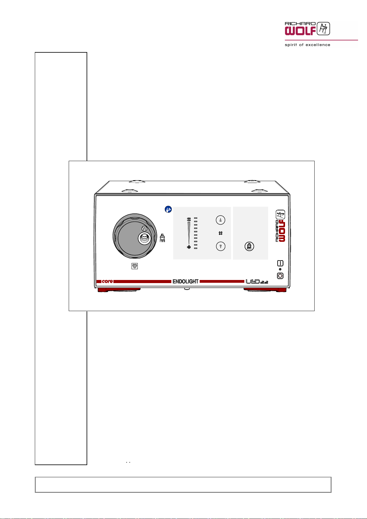
The device or system in the following called product
productproduct
product always relates to the ENDOLIGHT LED 2.2.
Guidelines
GuidelinesGuidelines
Guidelines and
andand
and manufacturer's
manufacturer'smanufacturer's
manufacturer's declaration
declarationdeclaration
declaration -
--
- Electromagnetic
ElectromagneticElectromagnetic
Electromagnetic emissions
emissionsemissions
emissions
The product is intended for use in the environment specified below. The user must assure that the product is used in such an environment.
Emissions
EmissionsEmissions
Emissions measurement
measurementmeasurement
measurement /
//
/ test
testtest
test Compliance
ComplianceCompliance
Compliance Electromagnetic
ElectromagneticElectromagnetic
Electromagnetic environment
environmentenvironment
environment -
--
- Guidelines
GuidelinesGuidelines
Guidelines
HF emissions to CISPR 11 Group 1
The product uses HF energy for its internal function.
The HF emission level is extremely low and it is not likely to cause any
interference in nearby electronic equipment.
HF emissions to CISPR 11 Class B
The product is suitable for use in all establishments, including domestic
establishments. This also includes establishments directly connected to
the public low voltage power supply network that supplies buildings used
for domestic purposes.
Harmonic emissions
to IEC 61000-3-2 Class A
In conformity with IEC 61000-3-3 “Emission of voltage fluctuations
/ flicker"
Guidelines
GuidelinesGuidelines
Guidelines and
andand
and manufacturer's
manufacturer'smanufacturer's
manufacturer's declaration
declarationdeclaration
declaration -
--
- Electromagnetic
ElectromagneticElectromagnetic
Electromagnetic immunity
immunityimmunity
immunity
The product is intended for use in the environment specified below. The user must assure that the product is used in such an environment.
Immunity
ImmunityImmunity
Immunity tests
teststests
tests IEC
IECIEC
IEC 60601
6060160601
60601 test
testtest
test level
levellevel
level Compliance
ComplianceCompliance
Compliance Electromagnetic
ElectromagneticElectromagnetic
Electromagnetic environment
environmentenvironment
environment -
--
- Guidelines
GuidelinesGuidelines
Guidelines
Electrostatic discharge (ESD)
to IEC 61000-4-2
±6 KV contact discharge
±8 KV air discharge Yes
Floors should be wood, concrete or ceramic tile.
With floors made of synthetic material, the relative
humidity of the ambient air must be at least 30%.
Electrical fast transience, bursts
to IEC 61000-4-4
±2 KV for power supply lines
±1 KV for input and output
lines
Yes Mains/line power quality should be that of a typical
commercial or hospital environment.
Surge voltage (surges)
to IEC 61000-4-5
±1 KV line to line
voltage
±2 KV line to ground
voltage
Yes Mains/line power quality should be that of a typical
commercial or hospital environment.
Voltage dips, short interruptions and sup
ply voltage variations
to IEC 61000-4-11
Voltage dip for 0.5 cycle
> 95% U
T
*
**
*
Voltage dip for 5 cycles
60% U
T
*
**
*
Voltage dip for 25 cycles
30% U
T
*
**
*
Voltage dip for 5 sec
> 95% U
T
*
**
*
Yes
Mains/line power quality should be that of a typical
commercial or hospital environment. If the user of
the product requires continued operation during
power mains/line interruptions it is recommended
that the product be powered from an uninterrupt
ible power supply or battery.
Power frequency (50/60 Hz) magnetic
field,
to IEC 61000-4-8
3 A/m Yes
Power frequency magnetic fields should be at lev
els characteristic of a typical location in a commer
cial or hospital environment.
*
**
* NOTE: U
T
is the line / mains voltage prior to application of the test level.

6
66
6
GA-A 307
Guidelines
GuidelinesGuidelines
Guidelines and
andand
and manufacturer's
manufacturer'smanufacturer's
manufacturer's declaration
declarationdeclaration
declaration -
--
- Electromagnetic
ElectromagneticElectromagnetic
Electromagnetic immunity
immunityimmunity
immunity for
forfor
for products
productsproducts
products that
thatthat
that are
areare
are not
notnot
not life-supporting
life-supportinglife-supporting
life-supporting
The product is intended for use in the environment specified below. The user must assure that the product is used in such an environment.
Immunity
ImmunityImmunity
Immunity tests
teststests
tests IEC
IECIEC
IEC 60601
6060160601
60601 test
testtest
test level
levellevel
level Compliance
ComplianceCompliance
Compliance Electromagnetic
ElectromagneticElectromagnetic
Electromagnetic environment
environmentenvironment
environment -
--
- Guidelines
GuidelinesGuidelines
Guidelines
Conducted HF interference
to IEC 61000-4-6
Radiated HF interference
to IEC 61000-4-3
3 V
rms
150 kHz to 80 MHz
3 V/m
80 MHz to 2.5 GHz
Yes
Portable and mobile RF communications equipment should
be used no closer to any part of the product, including ca
bles, than the recommended separation distance calculated
from the equation applicable to the frequency of the transmit
ter.
Recommended
RecommendedRecommended
Recommended separation
separationseparation
separation distance:
distance:distance:
distance:
d = 1.2 P
d = 1.2 P for 80 MHz to 800 MHz
d = 2.3 P for 800 MHz to 2.5 GHz
P = Nominal power output rating of the transmitter in watts
(W)
(according to the transmitter manufacturer)
d = recommended separation distance in meters (m)
Field strengths from fixed RF transmitters, as determined by
an electromagnetic site survey
1
11
1
, should be less than the
compliance level in each frequency range
2
22
2
.
Interference may occur in the vicinity of devices with the
following symbol:
REMARKS:
At 80 MHz and 800 MHz the higher frequency range applies. These guidelines may not apply in all situations. The propagation of electromag
netic waves is affected by absorption and reflexion from buildings, objects and people.
1
11
1 = The field strength of stationary transmitters (e.g. base station for radio phone, earth to earth radio stations,, amateur radio stations, radio
and television transmitters) cannot be exactly predicted in theory. To assess the EMC environment due to fixed transmitters an electromagnetic
site survey should be conducted. If the measured field strength in the location in which the product is used exceeds the applicable compliance
level above, the product should be observed to verify normal operation.
If abnormal performance is observed, additional measures may be required, such as reorienting or relocating the product.
2
22
2 = Over the frequency range between 150 kHz and 80 MHz the field strength should be below 3 V/m.
Recommended
RecommendedRecommended
Recommended separation
separationseparation
separation distances
distancesdistances
distances between
betweenbetween
between portable
portableportable
portable and
andand
and mobile
mobilemobile
mobile HF
HFHF
HF telecommunication
telecommunicationtelecommunication
telecommunication devices
devicesdevices
devices and
andand
and devices
devicesdevices
devices which
whichwhich
which
are
areare
are not
notnot
not life-supporting
life-supportinglife-supporting
life-supporting
The product is intended for use in an electromagnetic environment where HF disturbances are controlled.
The user can help prevent electromagnetic interference by maintaining a minimum distance between portable and mobile HF telecommunica
tions equipment and the product.
Rated
RatedRated
Rated nominal
nominalnominal
nominal output
outputoutput
output power
powerpower
power of
ofof
of
thetransmitter
thetransmitterthetransmitter
thetransmitter (W)
(W)(W)
(W)
Separation
SeparationSeparation
Separation distance
distancedistance
distance as
asas
as a
aa
a function
functionfunction
function of
ofof
of transmitter
transmittertransmitter
transmitter frequency
frequencyfrequency
frequency (m)
(m)(m)
(m)
150
150150
150 kHz
kHzkHz
kHz to
toto
to 80
8080
80 MHz
MHzMHz
MHz
d = 1.2 p
80
8080
80 MHz
MHzMHz
MHz to
toto
to 800
800800
800 MHz
MHzMHz
MHz
d = 1.2 P
800
800800
800 MHz
MHzMHz
MHz to
toto
to 2.5
2.52.5
2.5 GHz
GHzGHz
GHz
d = 2.3 P
0,01 0,12 0,12 0,23
0,1 0,38 0,38 0,73
1 1,2 1,2 2,3
10 3,8 3,8 7,3
100 12 12 23
For transmitters rated at a nominal output power not listed in the table above, the recommended separation distance (d) in meters (m) can be
determined using the applicable equation (observe frequency). P = nominal power of the transmitter in Watts (W).
REMARKS:
At 80 MHz and 800 MHz the higher frequency range applies. These guidelines may not apply in all situations. The propagation of electromag
netic waves is affected by absorption and reflexion from buildings, objects and people.

7
77
7
GA-A 307
1.7
1.71.7
1.7 Connection
ConnectionConnection
Connection diagram
diagramdiagram
diagram -
--
- light
lightlight
light source
sourcesource
source in
inin
in video
videovideo
video mode
modemode
mode
12
Legend
LegendLegend
Legend
Direct
DirectDirect
Direct connection
connectionconnection
connection
1
11
1 LAN (Ethernet) connection cable (option) -
core
corecore
core
nova System
2
22
2 Video cable in accordance with the signal types of the camera controller used
IMPORTANT!
IMPORTANT!IMPORTANT!
IMPORTANT!
Connect the LAN (Ethernet) connection cable (1
11
1) only
onlyonly
only in the case of an interactive
interactiveinteractive
interactive camera controller.

8GA-A 307
2
22
2 Illustration
IllustrationIllustration
Illustration
2.1
2.12.1
2.1 Front
FrontFront
Front view
viewview
view
1
11
1
1.1
1.11.1
1.1
3
33
3
4.1
4.14.1
4.1 3.1
3.13.1
3.1 2
22
2
4.2
4.24.2
4.2
4
44
4
Legend
LegendLegend
Legend
1
11
1 Power/mains switch 4
44
4 Selector wheel with light sockets
(type CF applied part)
1.1
1.11.1
1.1 Indicator light for line voltage (mains) ON/OFF 4.1
4.14.1
4.1 Light socket
2
22
2 Light On / Off 4.2
4.24.2
4.2 Indication of selected light socket
3
33
3 Manual brightness adjustment
3.1
3.13.1
3.1 Brightness level indicator

9
GA-A 307
2.2
2.22.2
2.2 Illustration
IllustrationIllustration
Illustration of
ofof
of rear
rearrear
rear panel
panelpanel
panel
6
66
65
55
5
7
77
7
9
99
9
FEDERAL LAW RESTRICTS THIS UNIT TO BE
USED OR SOLD, EXCEPT UNDER THE SUPER-
VISION OF A MEDICAL DOCTOR.
8
88
8
Legend
LegendLegend
Legend
5
55
5 Equipotential connector 8
88
8 Power input connector with fuse holder
6
66
6 LAN (Ethernet) network connector 9
99
9 Identification plate
7
77
7 Fuse plate

10
1010
10
GA-A 307
3
33
3 Setup
SetupSetup
Setup
WARNING!
WARNING!WARNING!
WARNING!
The
TheThe
The device
devicedevice
device is
isis
is not
notnot
not protected
protectedprotected
protected against
againstagainst
against explosions.
explosions.explosions.
explosions.
Explosion
ExplosionExplosion
Explosion hazard.
hazard.hazard.
hazard.
Do
DoDo
Do not
notnot
not operate
operateoperate
operate this
thisthis
this device
devicedevice
device in
inin
in areas
areasareas
areas where
wherewhere
where there
therethere
there is
isis
is a
aa
a danger
dangerdanger
danger of
ofof
of explosion.
explosion.explosion.
explosion.
WARNING!
WARNING!WARNING!
WARNING!
Danger
DangerDanger
Danger if
ifif
if a
aa
a power
powerpower
power supply
supplysupply
supply without
withoutwithout
without protective
protectiveprotective
protective earth
earthearth
earth is
isis
is used.
used.used.
used.
Danger
DangerDanger
Danger of
ofof
of electric
electricelectric
electric shock!
shock!shock!
shock!
Connect
ConnectConnect
Connect the
thethe
the device
devicedevice
device only
onlyonly
only to
toto
to a
aa
a power
powerpower
power supply
supplysupply
supply with
withwith
with protective
protectiveprotective
protective earth
earthearth
earth connec
connecconnec
connec
tor.
tor.tor.
tor.
NOTE!
NOTE!NOTE!
NOTE!
The line / mains voltage must be the same as the voltage indicated on the
identification plate. Connect the device only via the supplied power cable
or a power cable with the same specifications.
Do not block the ventilation slots!
IMPORTANT!
IMPORTANT!IMPORTANT!
IMPORTANT!
Do not the open the device!
CAUTION!
CAUTION!CAUTION!
CAUTION!
Danger
DangerDanger
Danger of
ofof
of faults
faultsfaults
faults and
andand
and malfunctions.
malfunctions.malfunctions.
malfunctions.
To
ToTo
To guarantee
guaranteeguarantee
guarantee the
thethe
the safety
safetysafety
safety of
ofof
of the
thethe
the user,
user,user,
user, patient
patientpatient
patient and
andand
and others,
others,others,
others, use
useuse
use only
onlyonly
only acces
accesacces
acces
sories
soriessories
sories and
andand
and spare
sparespare
spare parts
partsparts
parts specified
specifiedspecified
specified by
byby
by the
thethe
the manufacturer
manufacturermanufacturer
manufacturer of
ofof
of this
thisthis
this product.
product.product.
product.
Other
OtherOther
Other accessories
accessoriesaccessories
accessories or
oror
or spare
sparespare
spare parts
partsparts
parts can
cancan
can cause
causecause
cause the
thethe
the emission
emissionemission
emission of
ofof
of increased
increasedincreased
increased
electromagnetic
electromagneticelectromagnetic
electromagnetic radiation
radiationradiation
radiation or
oror
or reduced
reducedreduced
reduced immunity
immunityimmunity
immunity against
againstagainst
against interference.
interference.interference.
interference.
IMPORTANT!
IMPORTANT!IMPORTANT!
IMPORTANT!
Medical devices are subject to special precautions with regard to electro
magnetic compatibility (EMC
EMCEMC
EMC).
Make sure you follow the notes on EMC for installation and operation.
Medical electrical devices can be influenced by mobile HF communication
devices.
If it is necessary to stack the devices or place them next to each other
and HF interference is observed, make sure that the devices are oper
ated as specified in the intended use.
CAUTION!
CAUTION!CAUTION!
CAUTION!
Device
DeviceDevice
Device failure
failurefailure
failure due
duedue
due to
toto
to automatic
automaticautomatic
automatic over-temperature
over-temperatureover-temperature
over-temperature cut-out.
cut-out.cut-out.
cut-out.
In
InIn
In the
thethe
the case
casecase
case of
ofof
of insufficient
insufficientinsufficient
insufficient air
airair
air supply,
supply,supply,
supply, the
thethe
the over-temperature
over-temperatureover-temperature
over-temperature cut-out
cut-outcut-out
cut-out may
maymay
may be
bebe
be
triggered
triggeredtriggered
triggered which
whichwhich
which will
willwill
will shut
shutshut
shut down
downdown
down the
thethe
the device
devicedevice
device during
duringduring
during use.
use.use.
use.
Units
UnitsUnits
Units with
withwith
with a
aa
a cooling
coolingcooling
cooling device
devicedevice
device [e.g.
[e.g.[e.g.
[e.g. fan]
fan]fan]
fan] require
requirerequire
require a
aa
a minimum
minimumminimum
minimum distance
distancedistance
distance of
ofof
of 15
1515
15 cm
cmcm
cm
from
fromfrom
from the
thethe
the wall
wallwall
wall and
andand
and unobstructed
unobstructedunobstructed
unobstructed vent
ventvent
vent slots.
slots.slots.
slots. Do
DoDo
Do not
notnot
not cover
covercover
cover any
anyany
any openings
openingsopenings
openings
required
requiredrequired
required for
forfor
for cooling.
cooling.cooling.
cooling.
To
ToTo
To prevent
preventprevent
prevent possible
possiblepossible
possible accumulation
accumulationaccumulation
accumulation of
ofof
of heat
heatheat
heat in
inin
in the
thethe
the closed
closedclosed
closed system
systemsystem
system cart,
cart,cart,
cart, place
placeplace
place
the
thethe
the devices
devicesdevices
devices accordingly
accordinglyaccordingly
accordingly and/or
and/orand/or
and/or provide
provideprovide
provide vent
ventvent
vent slots.
slots.slots.
slots.
NOTE!
NOTE!NOTE!
NOTE!
To prevent liquid from being aspirated via the ventilation system, do not
place any products or items from which liquids may leak onto or above
the light source.

11
1111
11
GA-A 307
3.1
3.13.1
3.1 Connection
ConnectionConnection
Connection to
toto
to the
thethe
the
core
corecore
core
nova
novanova
nova system
systemsystem
system
IMPORTANT!
IMPORTANT!IMPORTANT!
IMPORTANT!
The plug of the LAN (ethernet) connection cable must engage in the LAN
(Ethernet) network socket of the device.
Use only LAN (Ethernet) connection cables with the corresponding lock
ing tab on the plug.
IMPORTANT!
IMPORTANT!IMPORTANT!
IMPORTANT!
After connecting the devices to the core
corecore
core system, carry out a function test
with the devices.
IMPORTANT!
IMPORTANT!IMPORTANT!
IMPORTANT!
Do
DoDo
Do not
notnot
not connect a second light source to the core
corecore
core nova system via LAN
(Ethernet) or via the network switch in the same network.
3.2
3.23.2
3.2 Selecting
SelectingSelecting
Selecting the
thethe
the light
lightlight
light socket
socketsocket
socket
The light source is equipped with a rotary selector wheel (4
44
4) with 4 light
sockets for connecting light cables of other manufacturers.
Turn the light socket for the light cable to be used to the 3-o'clock posi
tion (4.1
4.14.1
4.1).
The manufacturer's code is displayed in the window (4.2
4.24.2
4.2).
4.2
4.24.2
4.2
4.1
4.14.1
4.1
4
44
4
Manufacturer's
Manufacturer'sManufacturer's
Manufacturer's code
codecode
code
W
WW
W =
==
= WOLF
WOLFWOLF
WOLF
S
SS
S =
==
= STORZ
STORZSTORZ
STORZ
O
OO
O =
==
= OLYMPUS
OLYMPUSOLYMPUS
OLYMPUS
A
AA
A =
==
= ACMI
ACMIACMI
ACMI

12
1212
12
GA-A 307
3.3
3.33.3
3.3 Preparation
PreparationPreparation
Preparation
NOTE!
NOTE!NOTE!
NOTE!
To achieve optimum light transmission, the fiber bundle diameters of the
endoscope and fiber light cable must be the same.
Possible consequences when using a fiber light cable with
excessive diameter: excessive heating at the coupling point with the
endoscope
insufficient diameter: reduced light output, excessive heating of light
socket and fiber light cable.
For the suitable fiber bundle diameter please refer to the product number
of the fiber light cable.
In the type number the two digits to the right of the decimal point must
correspond with the code number on the cold-light connector.
IMPORTANT!
IMPORTANT!IMPORTANT!
IMPORTANT!
In video mode and when combined with an interactive camera controller,
the brightness of the light source is controlled via the dialog
dialogdialog
dialog function (see
section 5.2.1).
The shutter function of the camera controller must be activated and the
LAN (Ethernet) connection cable between the light source and the cam
era controller must be connected.
Connect additional devices such as a monitor and a camera controller
in accordance with the wiring schematic in section 1.
Connect the endoscope in accordance with the illustration.
23
2323
23
22
2222
22
24
2424
24
25
2525
25
LAN (Ethernet)
Connection cable
(option)
Legend
LegendLegend
Legend
22
2222
22 Fiber light cable 24
2424
24 Camera head with objective lens
23
2323
23 Endoscope 25
2525
25 Camera controller
35
35

13
1313
13
GA-A 307
4
44
4 Checks
ChecksChecks
Checks
IMPORTANT!
IMPORTANT!IMPORTANT!
IMPORTANT!
Run through the checks before and after each use.
Do not use the products if they are damaged or incomplete or have loose
parts.
Return damaged products together with any loose parts for repair.
Do not attempt to do any repairs yourself.
4.1
4.14.1
4.1 Visual
VisualVisual
Visual check
checkcheck
check
Check the device and accessories for damage, loose or missing parts,
hygiene and completeness.
Check all connection cables for damage.
Any inscription, lettering or labeling necessary for the safe intended
use must be legible.
Missing inscriptions, lettering or labeling leading to wrong handling or
reprocessing must be reinstated.
4.2
4.24.2
4.2 Function
FunctionFunction
Function check
checkcheck
check
IMPORTANT!
IMPORTANT!IMPORTANT!
IMPORTANT!
Before you perform the function checks, make sure that the devices are
in perfect working order and are set up correctly. This must also be guar
anteed within the scope of the visual check.
When
WhenWhen
When operated
operatedoperated
operated within
withinwithin
within the
thethe
the
core
corecore
core
system:
system:system:
system:
Check the devices connected to the
core
corecore
core
system for proper functioning
within the
core
corecore
core
system.
4.2.1
4.2.14.2.1
4.2.1 Device
DeviceDevice
Device function
functionfunction
function after
afterafter
after switching
switchingswitching
switching on
onon
on the
thethe
the device
devicedevice
device
Switch on the device with the power switch.
When the self test starts, also listen for a signal being sounded for
checking the speaker function.
The indicator lamp on the power switch is lit.
All brightness indicator LEDs light up briefly.
The Light
LightLight
Light ON/OFF
ON/OFFON/OFF
ON/OFF button is not lit
The light source LED is switched off.
The cooling fan operates after switching on the device.

14
1414
14
GA-A 307
4.2.2
4.2.24.2.2
4.2.2 Manual
ManualManual
Manual brightness
brightnessbrightness
brightness adjustment
adjustmentadjustment
adjustment
CAUTION!
CAUTION!CAUTION!
CAUTION!
Danger
DangerDanger
Danger of
ofof
of glare.
glare.glare.
glare.
Do
DoDo
Do not
notnot
not look
looklook
look into
intointo
into the
thethe
the open
openopen
open end
endend
end of
ofof
of the
thethe
the light
lightlight
light cable
cablecable
cable when
whenwhen
when the
thethe
the light
lightlight
light cable
cablecable
cable is
isis
is
connected.
connected.connected.
connected.
Adjust the brightness across the entire adjustment range using the "in
crease/decrease brightness" buttons.
The corresponding LEDs of the bar indicator light up.
No light must escape from the light socket when no
nono
no light cable is con
nected.
When reaching the upper or lower range limit a signal is sounded.
4.2.3
4.2.34.2.3
4.2.3 Switching
SwitchingSwitching
Switching ON
ONON
ON and
andand
and OFF
OFFOFF
OFF the
thethe
the LED
LEDLED
LED
Switching
SwitchingSwitching
Switching on
onon
on the
thethe
the LED:
LED:LED:
LED:
Push the “Light
LightLight
Light" button to switch on the LED.
When no
nono
no light cable is connected the LED must be off.
Switching
SwitchingSwitching
Switching off
offoff
off the
thethe
the LED:
LED:LED:
LED:
Push the “Light
LightLight
Light" button again to switch off the LED.
4.2.4
4.2.44.2.4
4.2.4 Automatic
AutomaticAutomatic
Automatic brightness
brightnessbrightness
brightness adjustment
adjustmentadjustment
adjustment using
usingusing
using the
thethe
the
“
““
“dialog"
dialog"dialog"
dialog" function
functionfunction
function
CAUTION!
CAUTION!CAUTION!
CAUTION!
Danger
DangerDanger
Danger of
ofof
of glare.
glare.glare.
glare.
Do
DoDo
Do not
notnot
not look
looklook
look into
intointo
into the
thethe
the open
openopen
open end
endend
end of
ofof
of the
thethe
the light
lightlight
light cable
cablecable
cable when
whenwhen
when the
thethe
the light
lightlight
light cable
cablecable
cable is
isis
is
connected.
connected.connected.
connected.
Connect
ConnectConnect
Connect the
thethe
the interactive
interactiveinteractive
interactive
(i.e. dialog-capable) camera controller in accor
dance with section 1.
the light cable to the light source.
Switch on the light source and the camera controller..
Push the “Light
LightLight
Light" button to swich on the LED.
The
dialog
dialogdialog
dialog
function is active as a default setting (see section 5.2.1).
Illuminate an object with white light.
The camera controller automatically controls the brightness. In this
case, manual brightness control is not possible.

15
1515
15
GA-A 307
5
55
5 Use
UseUse
Use
5.1
5.15.1
5.1 Operation
OperationOperation
Operation
The ENDOLIGHT LED 2.2 light source is used for illuminating the operat
ing field in the patient's body. For this purpose the light is transmitted
from the light source via a light cable to the instrument tip.
With activated shutter function (ELC ON) on the camera controller, in the
case of varying image brightness automatically a constant image bright
ness is adjusted.
The color temperature of the LED light source is approx. 6500 K.
Optimum ventilation and adherence to the operating notes and instruc
tions allows an LED service life of approx. 30000 h.
5.2
5.25.2
5.2 Control
ControlControl
Control elements
elementselements
elements and
andand
and modes
modesmodes
modes
5.2.1
5.2.15.2.1
5.2.1
Dialog
DialogDialog
Dialog
function
functionfunction
function
The
dialog
dialogdialog
dialog
function allows for communication between the light source
and an
interactive
interactiveinteractive
interactive
(i.e. dialog-capable) camera controller.
The
dialog
dialogdialog
dialog
function uses the fast ELC control of the camera controller to
adapt the image brightness while also automatically controlling the bright
ness of the light source.
The brightness setting of the light source is controlled automatically via
the camera controller. It is not possible to control the brightness manually
at the light source.
For this purpose the devices must be connected via a LAN (Ethernet)
connection cable (see wiring schematic in section 1)
In both devices, the setting for the "
core
corecore
core
nova LAN“ OR integration inter
face must be selected.
NOTE!
NOTE!NOTE!
NOTE!
We recommend working with the activated dialog
dialogdialog
dialog function at
atat
at all
allall
all times
timestimes
times.
To deactivate the dialog
dialogdialog
dialog function it is necessary to disconnect the LAN
(Ethernet) connection.
5.2.2
5.2.25.2.2
5.2.2 Automatic
AutomaticAutomatic
Automatic switch-on
switch-onswitch-on
switch-on of
ofof
of the
thethe
the device,
device,device,
device, i.e.
i.e.i.e.
i.e. "safe
"safe"safe
"safe start“
start“start“
start“ (e.g.
(e.g.(e.g.
(e.g. after
afterafter
after power
powerpower
power failure)
failure)failure)
failure)
Device
DeviceDevice
Device failure
failurefailure
failure for
forfor
for less
lessless
less than
thanthan
than 5
55
5 seconds:
seconds:seconds:
seconds:
The last parameters entered are used.
If “Light
LightLight
Light” was on, the LED is switched on again.
Device
DeviceDevice
Device failure
failurefailure
failure between
betweenbetween
between 5
55
5 and
andand
and 30
3030
30 seconds:
seconds:seconds:
seconds:
The last parameters entered are used.
If the LED was on, the safe
safesafe
safe start
startstart
start function is activated automatically.
The “Light“
“Light““Light“
“Light“ button blinks. Switch on the LED again.
Device
DeviceDevice
Device failure
failurefailure
failure for
forfor
for more
moremore
more than
thanthan
than 30
3030
30 seconds:
seconds:seconds:
seconds:
A standard device start with self test is carried out.
The LED is switched off, and the brightness is automatically set to
80%.

16
1616
16
GA-A 307
5.2.3
5.2.35.2.3
5.2.3 Manual
ManualManual
Manual brightness
brightnessbrightness
brightness adjustment
adjustmentadjustment
adjustment
The brightness can be adjusted across the entire adjustment range
using the "increase/decrease brightness" buttons.
The corresponding LEDs of the bar indicator light up.
The
dialog
dialogdialog
dialog
function must not
notnot
not be active.
When the upper or lower range limit is reached a signal is sounded.
5.2.4
5.2.45.2.4
5.2.4 Temperature
TemperatureTemperature
Temperature protection
protectionprotection
protection circuit
circuitcircuit
circuit
Blocked vent slots in the device rear panel or insufficient air circulation
can cause increased temperatures inside the device.
A temperature protection circuit monitors the device temperature. In the
case of overtemperature, the LED brightness is in a first stage continu
ously reduced and then shut down if the temperature increases any fur
ther in order to avoid additional damage.
Table of contents
Other Richard Wolf Medical Equipment manuals
Popular Medical Equipment manuals by other brands

Arjo
Arjo Flowtron ACS900 Instructions for use

Cochlear
Cochlear Baha Instructions for use

Savaria
Savaria Track Bridge M92940 Series owner's manual

InMode
InMode InMode System with BodyFX Handpiece Operator's manual

Labex
Labex COMFORT ELECTROLARYNX user manual

Atos Medical
Atos Medical PROVOX Vega Instructions for use