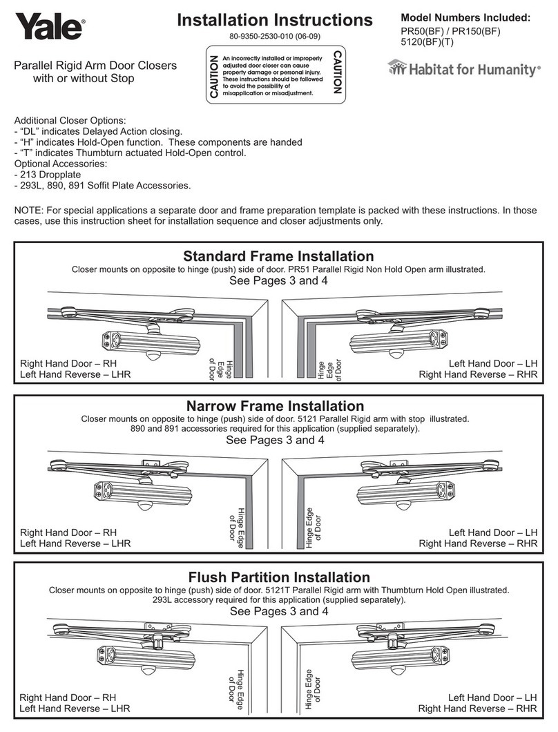
• Remove the top lid Aand bottom lid Iin accordance with image on the next
page, and pull out the push front Ffrom the outer prole E
• Set the dip-switches as desired, as described on the last page
• Adjust the length of the wire to the connection terminal with margin
• Thread the cabling through the cable outlet Con the outer prole E
• Install the cabling according to diagram J
• Slide the push front Fdown the outer prole Eso they are
edge to edge
• Mount outer prole Ewith screws at screw holes Band H
• It is possible to mount the outer prole Ein the wall box using the screw holes
adjacent cable outlet C. This is done when the push front Fslides down into the
outer prole E
• Mount the top lid Aand bottom lid Iso it “clicks”
• Turn on, wait a few seconds until the unit starts up
MOUNTING AND INSTALLATION
• Cable outlet 599 mm or 680 mm from the the lower edge, with the bottom lid mounted
• Recommended height: about 120 mm from the oor to the lower edge
• Cable: H05V-U (EK)
H05V-K (RK) is ok with the use of wire end ferrules
Minimum cross section area according to cable standard
HD21 is 0.5 mm2for EK and RK
• When mounted outdoors: Drill a drain hole in marked depression in the bottom lid
PREPARATION
TECHNICAL SPECS
Dimensions 799 x 95 x 25 mm
Power supply 18-30 VDC
Connection cable 3 wires minimum
Power consumption Standby ≈ 30mA
Activated ≈ Max 47mA
Relay, max rated current Per pole: 2A • Totally max: 6A
Material Outer prole and Push front Aluminum
Material Lids Polyamide
