PRITEC ACROS 80S User manual
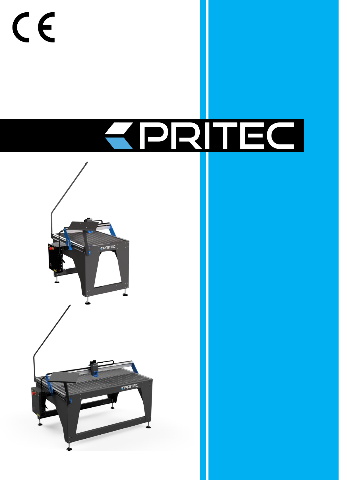
ACROS
80S/150S
CNC CUTTING TABLE
MANUAL

1
Table of contents
1. General information
.................................................................................................................................................................... 2
1.1 Introduction ............................................................................................................................................................................ 2
1.2 How does the process work? .................................................................................................................................................. 2
1.3 What is G code? ...................................................................................................................................................................... 2
1.4 How do I create G-code? ......................................................................................................................................................... 3
2. Safety instructions ......................................................................................................................................................................... 3
2.1 Basic principle of safety in the workplace .............................................................................................................................. 3
2.2 Basic safety regulations for working with machines ............................................................................................................. 3
2.3 Specific safety regulations for CNC cutting tables ................................................................................................................. 5
2.4 Description of warning stickers .............................................................................................................................................. 6
3. Accessory checklist ........................................................................................................................................................................ 7
4. Technical specifications ................................................................................................................................................................. 8
4.1 Machine specifications ........................................................................................................................................................... 8
4.2 Minimum laptop specifications .............................................................................................................................................. 8
4.3 Plasma cutter air supply ......................................................................................................................................................... 8
5. Machine assembly ......................................................................................................................................................................... 9
5.1 Transport and storage ........................................................................................................................................................... 10
6. Software installation ................................................................................................................................................................... 11
6.1 Installation software for PRITEC ACROS ............................................................................................................................... 11
6.2 Installing software to write G-code ...................................................................................................................................... 17
7. Start-up ........................................................................................................................................................................................ 17
7.1 Setting the workpiece zero point ......................................................................................................................................... 18
7. 2 Tests ...................................................................................................................................................................................... 19
9. Torch Height Control (THC) ......................................................................................................................................................... 19
9.1 Settings .................................................................................................................................................................................. 19
9.2 Determining THC voltage ...................................................................................................................................................... 21
9.3 THC connection ..................................................................................................................................................................... 21
10. Control panel (basic elements) ................................................................................................................................................. 23
11. Maintenance overview ............................................................................................................................................................. 24
12. Problem detection ..................................................................................................................................................................... 24
12.1 The machine does not switch on ........................................................................................................................................ 24
12.2 Controls not working .......................................................................................................................................................... 24
12.3 Plasma cutter does not cut through the material .............................................................................................................. 24
13. Warranty .................................................................................................................................................................................... 24
EC - Declaration of Conformity ....................................................................................................................................................... 26

2
1. General information
Before using this machine, you must first read and understand the operating instructions completely.
This manual contains important information regarding the proper installation, operation and maintenance of
the equipment described herein. There are several risks of injury or property damage associated with the use
of any CNC cutting table. Anyone who comes into contact with the installation, maintenance or operation of
the CNC cutting table must be fully familiar with the contents of this manual. To protect yourself from
personal injury or property damage, follow the following directions and instructions in this manual.
Every PRITEC CNC cutting table is produced in accordance with the Machinery Directive 2006/42/EC. A manual
including maintenance overview is supplied with every CNC cutting table. These must be kept and maintained
properly.
Because continuous improvements are made to the equipment with a view to quality, PRITEC reserves the right to
change specifications of the equipment described in the manual.
1.1 Introduction
This manual will help you get started with using your PRITEC ACROS. Read the manual carefully so that you can make
full use of your cutting table and cut the most fantastic products.
1.2 How does the process work?
The table has a control program called Mach3 CNC controller. You can install this program on your laptop by
following the steps in this guide. With this program you can 'manually' control the machine with your laptop.
If you want to automatically cut out a workpiece, you can load a G-code into the control program and then let it play
back.
1.3 What is G code?
G-code is a command used when programming a CNC program .
This G code is an instruction for the machine. The code has a structure with the letter G, followed by a number, for
example G26. The number after the G has a meaning. The numbers 0 to 99 have a fixed meaning that is laid down in
an ISO standard. A G-code tells the machine what to do, in what order, with which tools, in which location and at
what speed and feed.
Not only G codes are important in a CNC program. M codes are also used. These machine auxiliary codes are as
important as the G codes themselves. A G code is used when machining a workpiece, while M codes are used more
as a supplement to give the machine additional instructions, for example M03 or M05. These codes are used, among
other things, to switch the plasma cutter head on or off. The use of these codes is not the only important thing about
a CNC program. The program is largely dependent on coordinates and values that determine the accuracy and
correctness of a workpiece.

3
1. 4 How do I create G-code?
To create G-code you need a program that allows you to create a 2D or 3D file. This file contains the geometry of the
workpiece to be cut. In general you can create this with 2D or 3D drawing software. You then need a program to
convert the geometry into a G-code that the machine can read. Sometimes both processes can be performed with
the same program. Check out our site for the possibilities https://www.pritec-automation.com
2. Safety regulations
2.1 Basic principle of safety in the workplace
Most accidents occur because safety regulations are not taken into account or are ignored. Safety equipment
such as shields, safety glasses, dust masks, hearing protection, etc. reduce the risk of accidents. But even the
best safety measures provide no protection in the event of poor judgment, inattention or carelessness. Pay
attention at all times in the workshop and use common sense. If something seems too dangerous, don't try it,
but find a safer solution, even if it may take more time. Remember: your personal safety is your own
responsibility.
The user of the machine must be sure of the following:
Persons operating the machine have received instructions/training and have been made aware of the dangers and
safety regulations.
The safety regulations are complied with and can preferably be read at the workplace. For this reason, the manual
is part of the machine and must be kept within easy reach of the machine at all times. When the machine is resold,
the manual must be handed over!
2.2 Basic safety regulations for working with machines
1. Make sure you understand this manual before using the machine. Failure to follow this instruction may
result in serious personal injury, property damage and/or damage to the machine.
2. Make sure you have read and understood all warnings in this manual and those marked on the
machine. Failure to follow these warnings could result in serious personal injury.
3. Replace warning labels when they are no longer readable or have been removed.
4. This machine is designed and intended for use by professionals and experienced
staff. If you are not familiar with how to use the machine, do not use it until you have gained sufficient
experience and knowledge.
5. Do not use this machine for purposes other than those for which it is intended. If this does happen or if
the machine is modified, the warranty will be void and the manufacturer will not be liable for any
damage or injury caused as a result.
6. Always use ANSI approved safety glasses or face mask when operating this machine.
7. Do not wear jewelry, loose clothing and/or watches while using the machine, as these can get caught in
loose parts. Long hair should be tied back or put in a hairnet. Wearing non-slip footwear or applying anti
-slip strips to the floor is recommended.
8. Do not use this machine when you are tired or under the influence of
alcohol/medicines/drugs.
9. Check that the main switch is in the 0 position (OFF) before connecting the machine to the power
supply.

4
10. Never use this machine outdoors and never expose it to rain and/or moisture.
11. Never use the machine in a hazardous working environment. Using power tools in damp
environments or in the rain can cause electrocution.
12. Make sure the machine is properly grounded.
13. If an extension cord is used, be sure it is in good condition and can handle the power of the
machine. An extension cord that is too light can cause power loss and overheating. Refer to the
EN 60204-1:2006 standard for the correct size. This depends on the length of the cord and the
specifications of the machine.
14. When carrying out repairs or maintenance on the machine, the plug must be disconnected from the
power supply.
15. Only use accessories and mountings specified by the manufacturer, the use of other accessories/mountings
may cause damage to the machine and/or personal injury.
17. Remove materials, tools, keys, etc. from the machine before putting it into use.
18. Keep safety panels in place at all times when the machine is in use. If these are removed for
maintenance work, transport, etc., they must be replaced before the machine is put into use again.
Before use, check that all safety panels and/or guards are in place.
19. Do not force the workpiece and/or the machine. This may result in damage to the machine and/or
personal injury.
20. If a defect occurs during start-up or use of the machine, the operator must stop the machine and report
the defect to the workshop manager or technical service.
21. When the machine is not in use, it must be switched off.
22. Always adhere to the prescribed maintenance and inspection instructions that can be found in the user
manual.
23. Make sure the machine is securely secured to a solid, stable surface.
24. Check the machine for defective parts before each use. Before using the machine, check that any
damaged part still functions properly and can perform its intended function. Check the alignment of
moving parts, connection of moving parts, broken parts, assembly and other phenomena that may
affect the operation of the machine. In the event of a defective part or protection panel, the machine
must be taken out of use until the relevant part has been repaired or replaced. This may only be done
by a recognized company/technician and defective parts may only be replaced with original PRITEC
parts, which are available at your PRITEC sales point.
25. Ensure there is sufficient obligation and space around the workplace.
26. Keep the floor around the machine free of sharp materials, oil and grease.
27. Keep visitors at a safe distance from the workplace and keep children away.
28. Make your workshop “child-proof” by using padlocks on the main switches and by removing keys when the
machine is not in use.
29. Concentrate your attention completely on your work. Looking around, having conversations, etc.
distracts your attention, which can result in serious injuries.
30. Always maintain a steady footing and never overreach to avoid hitting the machine or other moving
parts.
31. Never overload the machine . Operate the machine at the correct speed and feed rate. Do not force the
machine to perform a task for which it is not intended.
32. Maintain your machine carefully. Keep it clean and replace worn parts for the best and safest
performance. Follow the instructions for cleaning, lubricating and replacing parts.
35. Switch off the machine before cleaning it or when carrying out maintenance on the machine. Use a brush or
compressed air to remove dust, chips, chips and dirt, not your hands.
36. Do not stand on the machine. If it falls over, serious injury may occur.
37. Never let the machine run unattended. Turn off the power and do not leave the machine until it has
come to a complete stop, as this could cause injury to unauthorized persons.
38. Remove loose objects and unnecessary workpieces from the workplace before starting the machine.

5
2.3 Specific safety regulations for CNC cutting tables
1. Do not use the machine until it has been assembled and installed according to the instructions in this
user manual.
2. If you are not familiar with/have never worked with a CNC cutting table before, please first be instructed
and/or guided by an experienced/specialized person.
3. Follow all technical requirements and prescribed electrical connections.
4. Use guards and protection at all times and check in advance that they are in place and functioning
properly.
5. Keep fingers, hands and arms away from gears and other rotating parts.
6. Avoid unusual controls and hand positions where unexpected slippage could result in contact with the
plasma head.
7. Never start the machine with the plasma head against the workpiece.
8. Use an extraction system.
9. Support long or wide workpieces with material supports/roll stands.
10. Disconnect the machine from the power supply before adjusting settings, installing or removing
accessories or when maintenance or repairs are carried out on the machine.
11. Disconnect the machine from the power supply and clean the machine and working
environment before leaving.
12. We recommend using the following Personal Protective Equipment (PPE): safety shoes, gloves and
safety glasses.
6
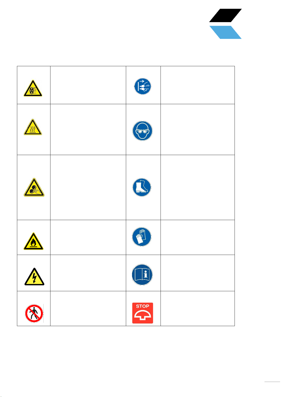
2.4 Description of warning stickers
NOTE: Place the CNC cutting
table in a well-ventilated area
and on a stable surface. Melting
metals can cause unpleasant
odors and smoke during cutting.
CAUTION: Disconnect the plug
from the socket in case of
emergency or short circuit.
WARNING: HOT, DO NOT TOUCH
The plasma cutter head and cut
workpieces reach high
temperatures during cutting.
Make sure everything has cooled
down before touching these
parts again. Or use the correct
gloves and PPE for this.
Safety glasses required
WARNING: MOVING PARTS Be
careful of your fingers and other
body parts when the cutting
table is in operation. The moving
parts of your PRITEC ACROS can
potentially cause damage. Do
not touch the rotating parts of
the cutting table when it is in
use.
Safety shoes required
WARNING: Do not place the
cutting table near flammable
materials.
Gloves required
NOTE: Be careful with electrical
voltage. The control box is
powered with 220 volts AC and
the output voltage is 24 volts DC.
Use instructions for use
WARNING: STAY NEAR THE CNC
CUTTING TABLE WHEN IT IS IN
USE.
PLEASE NOTE: The emergency
stop is mounted on the control
box and must be within reach at
all times during operation.

7
3. Accessory checklist
Description
Number
Power cable
1
USB cable
1
Cable guide with S-hook
1
Cable retention straps
3
Laptop support 3-piece +
4x M5x16 incl. nut and
washer
1
Cutting strips
22
Machine leveling feet
4
Control cable THC controller
1
8
4. Technical specifications
4.1 Machine specifications
Acros 150S
Acros 80S
Table dimensions (LxWxH)
1880 x 1260 x 1150mm
1200 x 1100 x 1100mm
Total weight
109kg
80kg
Cutting surface
1500 x 1000mm
800 x 1000mm
Cutting range
X-axis: 850mm | Y axis:
1415mm | Z axis: 65mm
X-axis: 635mm | Y axis:
850mm | Z axis: 65mm
Power supply
220V ~50hz 360W
220V ~50hz 360W
Work stress
24V DC
24V DC
4.2 Minimum laptop specifications
•32-bit Version of Windows 2000, Windows XP, Windows Vista,
or Windows 7 Operating System
•1Ghz CPU .
•512MB RAM.
Non-integrated video card with 32MB RAM
•1x USB
4.3 Plasma cutter air supply
Consult the plasma cutter manual for air supply requirements. We recommend installing a water separator in the air
supply for a better cutting result.
Control cable switching
plasma cutter on/off
1
9
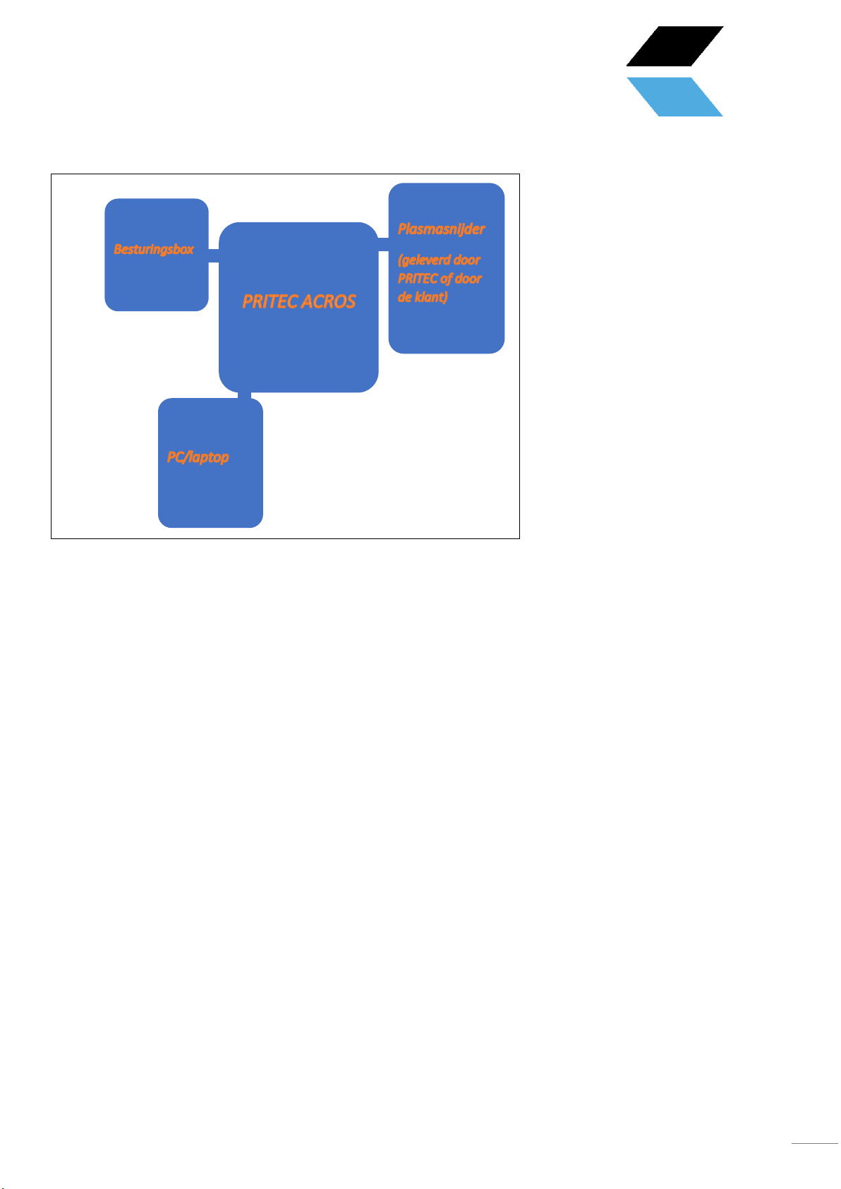
4.4 Machine layout
5. Machine assembly
Tools required for assembly:
•Allen key 3 and 5 mm
•Open-end wrench 13 mm 2x
Follow the instructions of the assembly drawing on the manuals page on our website.
Plasmasnijder
(geleverd door
PRITEC of door
Figuur 1

10
5.1 Transport and storage
Transporting material
When loading/unloading or transporting the equipment at the workplace, you must use suitable transport and
lifting equipment (e.g. crane/forklift, truck). Ensure that components are lifted and transported carefully so
that they cannot fall, taking into account package size, weight, center of gravity and fragile parts. Use a forklift
or pallet truck to transport the package (figure 1).
When the machine is out of the packaging, use a lifting strap or round
sling to transport the machine (figure 2).
Storage and stacking of packages
Packages containing the machine should be stored in a covered area, out of
direct sunlight and low humidity, at a temperature between -10°C and 40°C.
Stack a maximum of 3 packages on top of each other.
Unpack
When the machine is delivered, immediately check the package for possible damage due to transport and
storage. Check that the contents of the package are complete using the parts list and drawing. In case of
damage during transport, the customer must immediately inform the transport company. Packages should be
opened with attention to safety, keep a safe distance when opening tires and be careful not to let any parts
fall out of the package during opening.
Figuur 2

11
6. Software installation
For this installation you will need a laptop that has the correct specifications to run the software. (see 4.2 minimum
laptop specifications)
After installation, we recommend that you use the laptop's power cable as a power source instead of the laptop
battery when operating the ACROS.
6.1 Installation software for PRITEC ACROS control
Download operating software
The plasma table is controlled by so-called “control software”. The software is freely accessible and easy to
download via the website. The latest version of the operating software can be found at https://pritec-
automation.com/pages/downloads . This page explains where and how you can download the software.
Perform the installation
NB! Windows may ask you to enter an administrator password. This is caused by the installation program that
installs a driver to establish the connection with the plasma cutting table. This driver is important for the functioning
of the plasma cutting table and it will not be able to communicate with the computer if it is not installed.
A screenshot of the installer starting up.
After this screen, the installation of the Mach3 software starts. The installation of Mach3 must be completed step by
step to ensure that the product functions properly.

12
A screenshot of the Mach3 software installation welcome screen.
The installer recommends closing all Windows applications before the installation begins. Once this has been done,
click Next .
Read the following text carefully . Make sure the text is understood and then click Yes . If it is not agreed, click No .

13
Click Next .
Attention ! Make sure that Mach3 is always installed in C:\Mach3 . This is important for the correct installation of
the program. This is because the installer assumes that Mach3 is installed in C:\Mach3 to copy the profiles of the
machines.

14
Click Next .
This screen is not important for the installation itself, but can help keep your computer organized. You can enter
whatever you want here.
Click Next .

15
This is the final step before installing the software. Click Next .
This screen shows which files are being copied. Typically, installation takes no longer than three minutes. Do not
close the program if it takes longer.

16
The installation notes that external components have been successfully installed. Click OK .
This last screen shows the completion of the installation. After a short moment of patience, you will automatically
switch to the next screen.
Mach3 installation is complete! This menu offers the option to install additional components for the program. It has
been decided not to install any other profiles ( XMLs ) that come with the program and LazyCam will not be installed
either.
Load Mach3 driver is an option to immediately check whether the table can connect to the computer. If you are just
installing the software and the table is not connected to the computer at the time, you will see the following screen.
If the table is connected to the computer, the connection is tested.
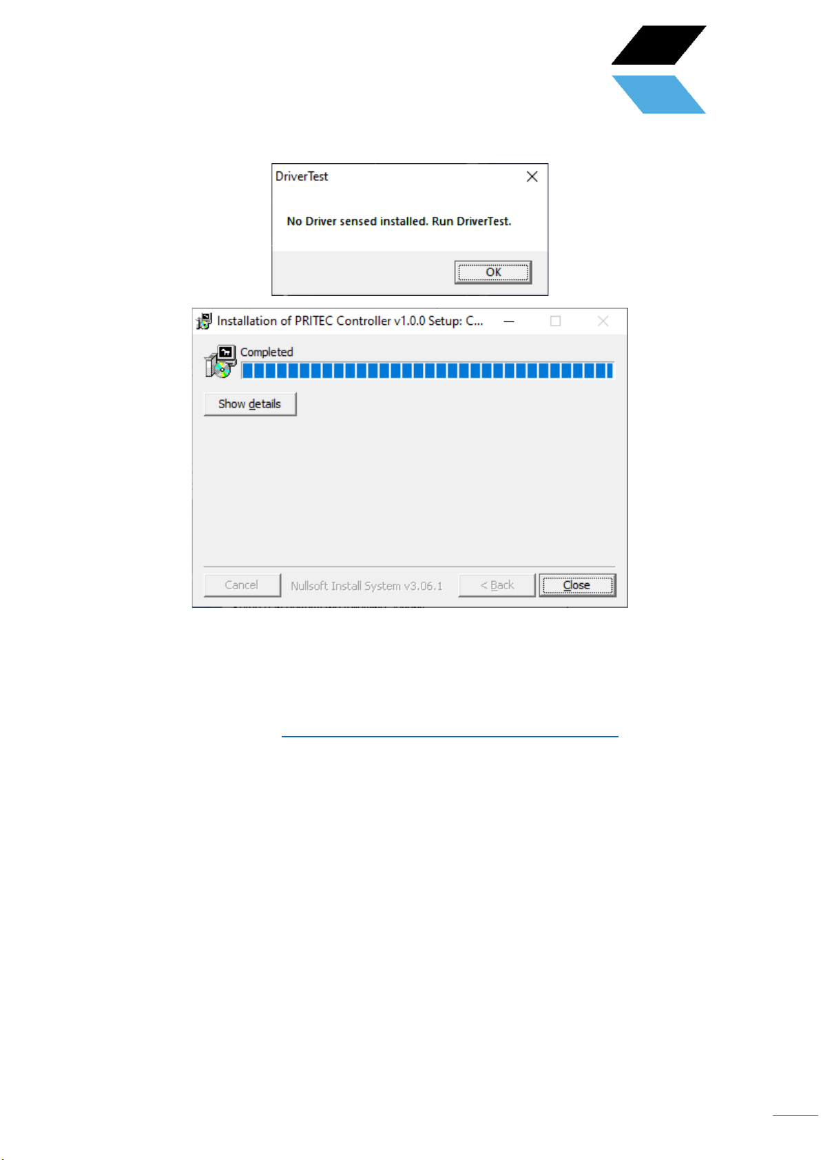
17
This final screen confirms the completion of the installation. The profiles have been copied, shortcuts created and
the program is ready to use. Click Close .
6.2 Installing software to write G-code
Generating a machine code (G-code) can be done using various programs. You may already have the right software
for this. If not, look for the options at https://pritec-automation.com/pages/kennis-artikelen
7. Start-up
1. Connect the USB cable to the control box and to your laptop.
2. Plug the power cable into the control box and switch on the red switch.
3. Open Mach3 CNC Controller and click on the blue RESET icon after startup. Make sure the emergency stop is
turned off. The ACROS can now be operated using the arrow keys on your keyboard (Z = Page Up/Page
Down). Use the space key on your keyboard to have the machine automatically return to its home position.
The machine will search for the home switches one by one.
18
7.1 Set workpiece zero point
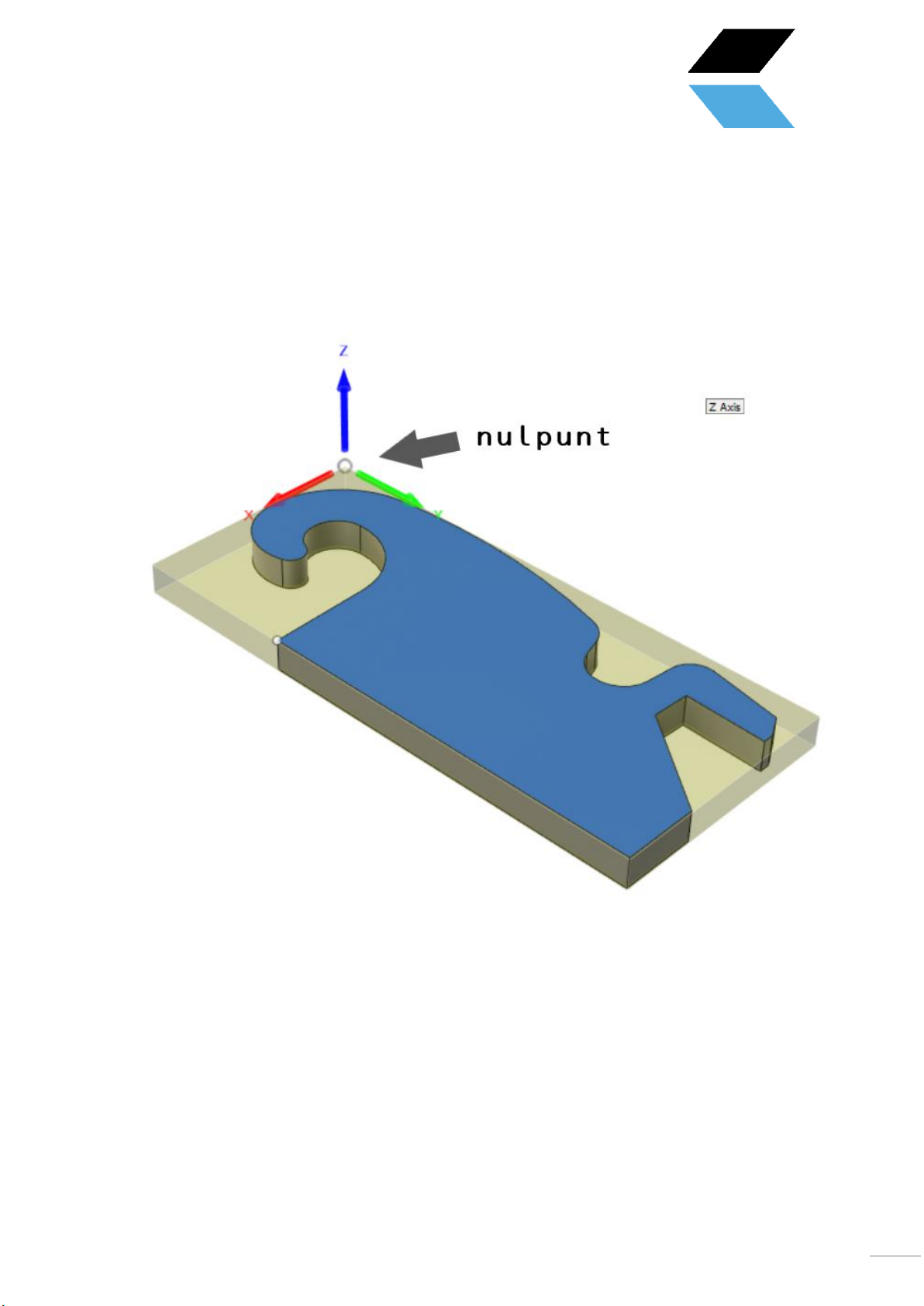
When you create a g-code, a zero point (reference point) is created. This is the starting point of the process. You can
set a zero point at any point on the table.
Figure 5 example zero point
1. Control the plasma head to the desired zero point position
2. See figure 4 number 4. Make sure the red LED indicator is turned off so that the zero point coordinates are
visible. Not the machine coordinates.
3. Now click on the X,Y and Z ZERO (see figure 4 number 2.) or click on ''zero all''. All three positions have now
switched to zero. The zero point position has now been determined.
4. If you want to return to this position, click on ''GO TO XYZ 0'' (see figure 4 number 3.)

19
7 . 2 Testing
NB! Make sure the table is level before you start testing.
1. Make sure the air compressor and plasma cutter are turned off .
2. Open a test file from the downloads page on our site.
3. Place a plate on the table.
4. Drive the machine to the desired position where you want to start cutting (see chapter 7.2). Make sure there
is enough space. To be on the safe side, steer towards the center of the plate so that there is at least 150
mm available on all sides.
5. “ZERO'' the X, Y and Z axis by clicking on the blue icons (the red lamp indication will turn green). ''ZERO'' is a
reference point so that the machine knows its position. You can set this anywhere you want. Make sure that
you set this point to the correct position due to the size of the workpiece to be cut out. You must prevent
the machine from cutting beyond its table limit.
6. Press the play icon. The machine will now play the G-code file.
7. If this goes without complications, continue with Chapter 9 .
9. Torch Height Control (THC)
The THC works as follows. A voltage is measured between the plus and minus poles of the plasma cutter using the
cable that you install from the control box to the plasma cutter. This voltage will change as the voltage of the arc
between the plasma head and the workpiece increases or decreases. After this has been set correctly, the THC will
respond by turning the Z axis up or down. As a result, the machine will continue to follow any bent plate so that the
plasma head does not come into contact with the workpiece. All this ensures a better cutting result.
With thicker plates it is not always necessary to use the THC because it will not warp quickly. If desired, you can then
disconnect the THC control cable from the control box, so that the THC controller does not receive any values and
will therefore not respond.
For more information go to:
https://pritec-automation.com/pages/toorts-hoogte-controller
9.1 Settings
The Proma SD is set with standard factory settings. After proper connection, it can be controlled by most plasma
cutters.
When you switch on the control box, the THC display will show an “animated” “THC” message. Then a flashing
voltage value will appear for one second. The controller then undergoes an automatic calibration.
Once the controller is ready for use, three dashes will appear on the display as shown in the third image above.
This manual suits for next models
1
Table of contents


