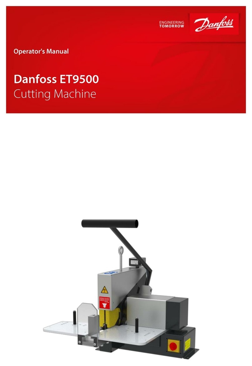
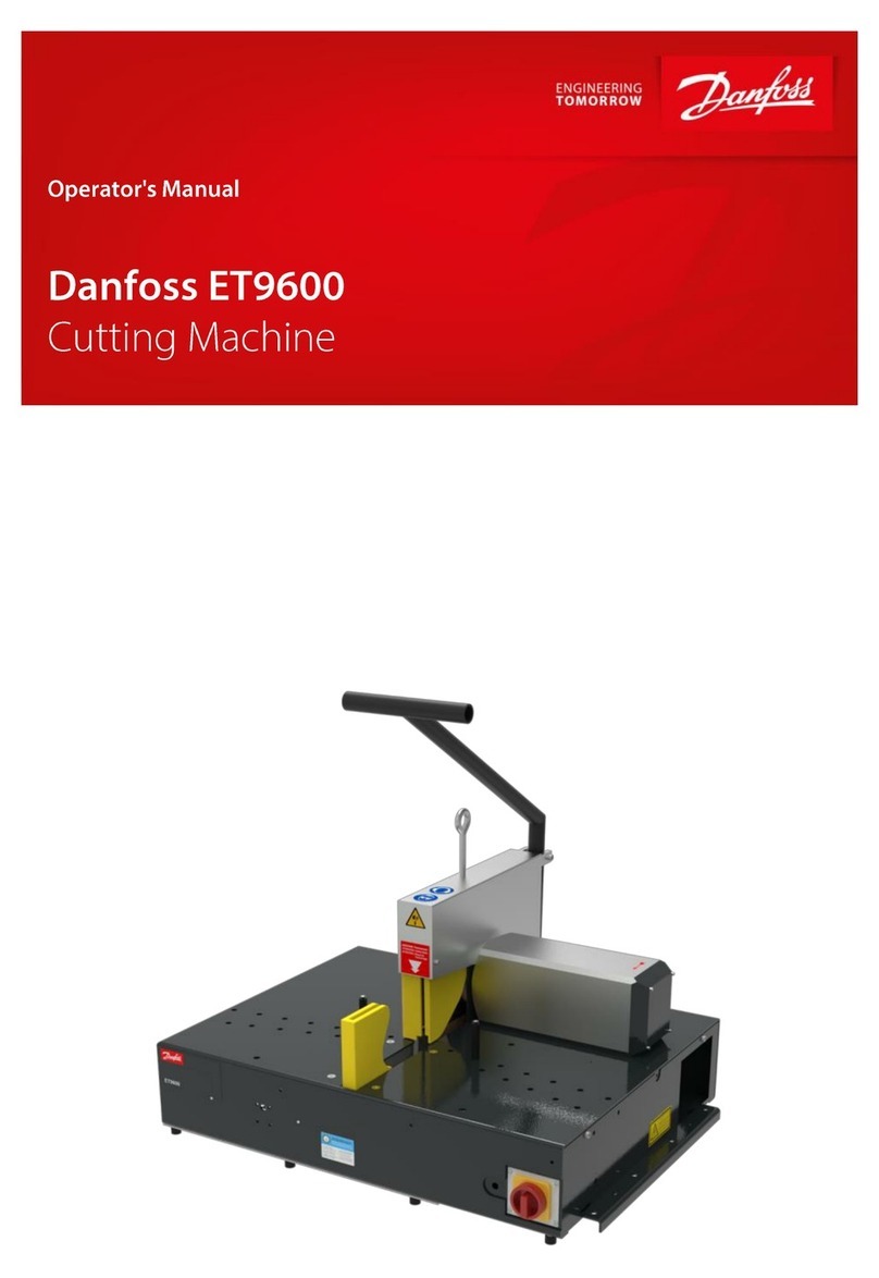
Danfoss ET9650 User manual


Imprint
Manufacturer:
UNIFLEX-Hydraulik GmbH
Robert-Bosch-Strasse 50-52
D-61184 Karben
Germany
Phone: +49 (0) 60 39 / 91 71 - 0
Fax: +49 (0) 60 39 / 91 71 - 181
This Operating Manual of the machine is a translation; the origi-
nal is in German.
Date of revision:2022-10-06
Version: 1.0
© Copyright by UNIFLEX-Hydraulik GmbH
Technical modifications reserved.
The reproduction, distribution and utilization of this document as well
as the communication of its contents to others without explicit authori-
zation are prohibited. Offenders will be held liable for the payment of
damages. All rights reserved in the event of the grant of a patent, util-
ity model or design.


EC / UK - Declaration of Conformity
In accordance with EC Machinery Directive 2006/42/EC and UK-Sup-
ply of Machinery (Safety) Regulations 2008.
The following machine
Danfoss ET9650
was developed, designed and manufactured in compliance with EC
Directive 2006/42/EC and UK-Supply of Machinery
(Safety) Regulations 2008, in the sole responsibility of
UNIFLEX-Hydraulik GmbH
Robert-Bosch-Strasse 50 - 52
D-61184 Karben
The following standards, codes and specifications have been applied:
•EC Directive 2006/42/EC
•EMC Directive 2014/30/EC
•EN ISO 12100: 2010
•EN 60204-1: 2018
•UK-Supply of Machinery (Safety) Regulations 2008
•UK-Electromagnetic Compatibility Regulations 2016
This declaration are invalid when the machine is modified or if unau-
thorized and unapproved third-party components are used without
our prior approval.
Entity authorised for documentation: Uniflex-Hydraulik GmbH, Tech-
nical Documentation Dept.
Karben, 06.10.2022
Managing Director Harald von Waitz

Contents
1About this document .......................................................................................... 7
1.1 Target groups ............................................................................................... 7
1.2 Storage.........................................................................................................8
1.3 Name plate ...................................................................................................9
1.4 Abbreviations................................................................................................9
2Safety instructions............................................................................................ 10
2.1 Presentation of warnings ............................................................................ 10
2.2 Intended use............................................................................................... 10
2.3 Product-specific risks.................................................................................. 11
2.3.1 Risks imposed by mechanical equipment........................................ 11
2.3.2 Risks imposed by electricity............................................................. 12
2.3.3 Risk imposed by pneumatic system ................................................ 12
2.3.4 Risks imposed by noise................................................................... 12
2.3.5 Risks in case of fire.......................................................................... 13
2.4 Safety.......................................................................................................... 13
2.4.1 Working area................................................................................... 13
2.4.2 Emergency-stop .............................................................................. 14
2.4.3 Warning signs on the machine ........................................................ 15
3Machine description.......................................................................................... 17
3.1 Design and function.................................................................................... 17
3.2 Accessories ................................................................................................ 18
3.3 Operation and display elements ................................................................. 19
3.4 Technical data ............................................................................................ 20
4Transport and commissioning......................................................................... 23
4.1 Transport .................................................................................................... 23
4.2 Intermediate storage of machine/unit.......................................................... 24
4.3 Commissioning ........................................................................................... 24
4.3.1 Extraction process for TM/TMG cutting knife................................... 25
4.3.2 Extraction process for TMC cutting knife......................................... 26
4.3.3 Connection of compressed air......................................................... 27
4.3.4 Electrical connection........................................................................ 28
4.3.5 Initial operation ................................................................................ 29
5Operation ........................................................................................................... 31

5.1 What you have to observe...........................................................................31
5.2 Start.............................................................................................................31
5.3 Work piece cutting.......................................................................................32
5.3.1 Prerequisites ....................................................................................32
5.3.2 Cutting individual hoses ...................................................................33
5.3.3 Setting the return stroke...................................................................35
5.4 Stop.............................................................................................................36
5.5 Overload protection.....................................................................................36
5.6 Cleaning ......................................................................................................37
6Maintenance.......................................................................................................39
6.1 What you have to observe...........................................................................39
6.2 Maintenance schedule.................................................................................39
6.3 Knife replacement........................................................................................41
6.4 Motor brake readjustment............................................................................42
7Troubleshooting.................................................................................................46
8Decommissioning, disposal..............................................................................47
8.1 Dismantling..................................................................................................47
8.2 Recycling.....................................................................................................47
8.3 Consumables and waste .............................................................................48
9Annex..................................................................................................................49
9.1 Accessories (upgradable)............................................................................49
9.2 Spare parts list.............................................................................................50
9.2.1 Mechanical equipment - Chassis......................................................50
9.2.2 Mechanical equipment - Knife protection .........................................51
9.2.3 Mechanical equipment - Covers.......................................................52
9.2.4 Electric equipment............................................................................54
9.2.5 Pneumatic equipment.......................................................................55
9.2.6 Wear parts........................................................................................56
9.3 Electric diagram...........................................................................................57
9.4 Pneumatic diagram......................................................................................58
9.5 Maintenance log..........................................................................................59
9.6 Declaration of qualified staff ........................................................................61

1 About this document
The "Cutting machine Danfoss ET9650" is consistently designated as
machine in this Operation Manual.
This Operation Manual includes important notes on how you operate
your machine/unit safely, properly and economically.
Use not in compliance with the intended purpose may result in hazard
to the operator's health and life and/or in the risk of damage to/the
machine/unit. Consequently, please only use the machine/unit
•in good order and condition,
•in accordance with its intended purpose,
•in a safety-conscious manner, with awareness of risks and haz-
ards,
•in compliance with all notes included in this Operation Manual.
The machine/unit may only be operated by staff who
•has read the Operation Manual,
•has understood it,
•has been instructed in the operation of the machine/unit, and
•has signed in the Annex.
Figures may include accessories/options. Customer-specific
equipment may vary.
The product images shown are for reference only and may differ
from the product delivered.
1.1 Target groups
The target groups of this Operation Manual are:
Owner
An owner is a natural person or entity using the device himself/her-
self/itself, or on whose behalf the device is used. An owner may ap-
point a representative to exercise the owner's rights and obligations.
The owner has to make sure that
•national provisions, occupational safety regulations and applica-
ble environmental protection regulations are fully complied with;

•persons working on the machine/unit are adequately qualified;
•persons working on the machine/unit are suitable for operating
the machine/unit;
•the Operation Manual has been read and understood. One hard-
copy of the Operation Manual must always be kept at a desig-
nated place where the machine/unit is used.
•persons working on the machine/unit are aware of potential
risks;
•the operating staff is familiar with the location as well as with op-
erating the fire alarm and fighting means. Free access to this
equipment must be ensured.
•personal protection equipment is worn (safety footwear, protec-
tion gloves and safety glasses).
Machine/unit fitters
Machine/unit fitters must be at least 18 years old and have completed
training for the task, i.e. they must have attended a specialist voca-
tional training.
A fitter
•must observe the instructions in the Operation Manual;
•must inform the owner on failures and damage.
Operator
An operator is a person charged with and instructed in the proper op-
eration of the machine/unit by the owner or the otherwise contractu-
ally obliged person.
The operator
•must observe the instructions in the Operation Manual;
•must inform the owner on failures and damage.
•must not perform and maintenance or repair work on the ma-
chine/unit.
1.2 Storage
The Operation Manual is part of the machine/unit and must be kept
near the machine/unit at all times. Upon disposal of the machine/unit,
the Operation Manual must also be handed over.

1.3 Name plate
The name plate is fixed near the power cable.
1.4 Abbreviations
TM cutting knife, plain
TMG cutting knife, with slots
TMC cutting knife, coated

2 Safety instructions
2.1 Presentation of warnings
Warning notes in the Operation Manual warn against risks involved
with the handling of the machine/unit. Risk levels are identified as fol-
lows:
The signal word HAZARD identifies an imminent hazard resulting in
serious injuries or death. This warning is supplemented by a triangu-
lar hazard symbol.
The signal word WARNING identifies a potentially hazardous situa-
tion, which might result in serious injuries or death. This warning is
supplemented by a triangular hazard symbol.
The signal word CAUTION identifies a potentially hazardous situa-
tion, which might result in light injuries. This warning is supplemented
by a triangular hazard symbol.
The signal word ATTENTION identifies a potentially hazardous situa-
tion, in which the product or property in the environment may be dam-
ages. This warning is supplemented by a hazard symbol or a excla-
mation mark.
2.2 Intended use
This machine is intended for industrial use; it is only suitable for cut-
ting pneumatic and hydraulic hoses up to a specific permissible dia-
meter, see “Technical Data” in Section 3.
Intended purposes include:
•Single user workplace for one person only
•Manual input and retrieval
•Operating temperatures between 5 °C and 40 °C
•Operation in a closed operation room
•The machine must not be operated by persons not capable of
operating the machine without any risk. These may include:
➢persons with physical or mental disabilities;
➢children and persons under age;
HAZARD!
WARNING!
CAUTION!
ATTENTION!

➢persons with a restricted capability for the operation of ma-
chines (e.g. under the influence of drugs, alcohol or narcot-
ics)
Use of the control in compliance with the intended purpose also inclu-
des compliance with the instructions in this Operation Manual.
Use for other than the intended purpose
Any other use is considered as being not in compliance with the in-
tended purpose, in particular:
•Design modifications of the machine
•Use in explosive environments
•Use of impermissible cutting knives
•Cutting of inflexible workpieces
•misuse of consumables and waste materials.
WARNING!
Risk for life and health!
Use not in compliance with the intended purpose imposes risks
for life and health. Consequences resulting from use for other
than the intended purpose shall be under the sole responsibility
of the owner.
•Always use the machine in compliance with its intended pur-
pose.
2.3 Product-specific risks
The machine/unit is designed in accordance with the latest state of
technology. Nevertheless, the machine/unit may impose risks:
2.3.1 Risks imposed by mechanical equipment
Cutting risk
A cutting risk exists during cutting and when the cutting knives are re-
placed.
•Take care and wear cut-proof protective gloves when cutting
and replacing knives.

Risk of squeezing
There is a risk of squeezing on the moving parts.
Tilting hazard
The risk of tilting mainly exists while the machine is being trans-
ported.
•Observe the machine's centre of gravity during transport.
2.3.2 Risks imposed by electricity
There is a risk of electrocution near the live parts!
•Work on electric systems may only be performed by qualified
electricians or instructed and trained persons under the supervi-
sion of a qualified electrician.
•Deactivate the machine/unit and secure it against unintentional
restart before maintenance.
2.3.3 Risk imposed by pneumatic system
Risks are imposed by all pneumatic lines and connections. Pneu-
matic systems are subject to special safety provisions.
•After the machine is deactivated, the given and potentially haz-
ardous residual energy has to be considered.
•Use correct hoses and hose clamps.
•Only work in the permissible pressure range.
2.3.4 Risks imposed by noise
The noise level meter acc. to IEC 804, Class 2, was calibrated before
measuring.
The operation of the machine causes noise emissions of 90 dB(A) at
the workplace. Noise protection is required.
Higher noise emissions may occur when other machinery is simulta-
neously used at the workplace. The machine owner must provide for
appropriate protection, e.g.
•instruct staff to wear ear protection;

•provide information/instructions on risks
•identify hazardous areas
•provide health monitoring
2.3.5 Risks in case of fire
The operating staff has to be familiar with the location as well as with
operating the fire alarm and fighting means. Free access to this
equipment must be ensured.
Use extinguishing powder in case of fire.
2.4 Safety
2.4.1 Working area
The working area is defined as the area all around the machine
(shaded).
•Keep the working area free from trip hazards.
•Use ducts for lines and cables.
•Provide good illumination.

2.4.2 Emergency-stop
The machine is fitted with an emergency-stop button.
Immediately activate the emergency-stop function (1) in cases of
emergency.
Remedy the cause of the emergency stop first before re-starting the
machine.

2.4.3 Warning signs on the machine
Cutting risk
on the cutting knife
Hand injury
on the cover
Danger from electric current
at the power supply line
Risk of eye injuries
Wear safety goggles

Risk of hearing damage
Wear ear protection
Illegible or missing warning signs must immediately be replaced by
the operator.

3 Machine description
3.1 Design and function
(1) Bending pin
(2) Protective cover
(3) Strap grip
(4) Machine cover
(5) Compressed air maintenance unit
(6) Foot pedal
(7) Motor
(8) Cutting plate
(9) Main switch
(10) Control valve for feed speed
(11) Knife protection
(12) Hose feed

(13) Return stroke setting
The machine requires an electrical connection and a compressed air
connection. The pressure of the compressed air can be adjusted at
the compressed air maintenance unit (5).
The bending pins (1) prevent the cutting knife from getting jammed by
the work piece and enhance the cutting performance. Once the bend-
ing pins (1) are positioned according to the hose diameter, the work
piece is placed onto the cutting plate (8) between the bending pins (1)
and hose feed (12). The knife protection (11) prevents the operator
from unintentionally reaching into the cutting knife.
Once the protective cover (2) is closed, the machine is switched on at
the main switch (9), which starts the motor (7) and drives the cutting
knife. To perform the cutting procedure, the foot pedal (6) is pressed,
which moves the work piece towards the cutting knife via the pneu-
matically driven hose feed (12). When the foot pedal (6) is released,
the hose feed (12) moves back into the starting position.
The control valve for feed speed (10) can be used to adjust the feed
speed gradually according to the respective work pieces. The se-
lected speed depends on the hose design.
The return stroke setting (13) can be used to gradually adjust the dis-
tance the hose feed (12) moves back towards the starting position. In
this way, the return stroke path can be adjusted according to the re-
spective diameter of the work piece.
3.2 Accessories
The machine may be fitted with accessories. A list of the available ac-
cessories is included in the Annex, Section "Accessories".

3.3 Operation and display elements
(1) Return stroke setting
(2) Feed speed
(3) Main switch / emergency-stop button

3.4 Technical data
Machine
Dimensions L x W x H
983 x 760 x 540 mm
Weight
approx. 140 kg
Noise level
85 dB(A)*
Protection class
IP 42
Operation mode
S6-60%
Function
Hose feed
Pneumatic
Brake motor
Yes
Extraction connection
Ø 60 mm
Cutting knife
TM C 400 x 4 x 30 mm
Work piece capacity
Workshop SAE R13 &
SAE R15
2"
Production SAE R13 & SAE R15
11/4"
SAE R12
2½"
Industry
4"
Max. outside
Ø 120 mm
Table of contents
Other Danfoss Cutter manuals