PRIZM Petit Crouto PRIZM v4 User manual

The PRIZM Sound Board User's Manual
Plecter Labs is in no way affiliated, associated, licensed or endorsed by Disney or Lucasfil Ltd., Industrial Light
and Magic or any of their associates.All brands and trade arks listed are the exclusive property of their respective
Owners.
1
Petit Crouton™ PRIZM v4
Single Cell Middle Range Illu inated Saber Controller
User’s anual
© Erv’ - Plecter Labs
February 2016
http://www.plecterlabs.co
Important release information
-3 channel direct drive Color ixing with the FlexiBlend™ engine
-Supports luxeon III, V, rebel (old or new), seoul LEDs, Ledengin, tri-rebels, tri-
Cree etc
-Trident™ (cross-guard) support
We spent a lot of time writing this manual to ensure all the important
information is provided for proper use of that board. If you are new to saber
building to the use of Petit Crouton boards or simply to electronics in
general we highly recommend you print a copy of that document and keep
it with you during the whole process of installing PC in your hilt.
Modification, copies or distribution of that docu ent is strictly prohibited
© Plecter Labs / Erv’ Plecter 2005-2016

The PRIZM Sound Board User's Manual
Plecter Labs is in no way affiliated, associated, licensed or endorsed by Disney or Lucasfil Ltd., Industrial Light
and Magic or any of their associates.All brands and trade arks listed are the exclusive property of their respective
Owners.
2
Index
PETIT CROUTON™ PRIZM V4 1
I
MPORTANT RELEASE INFORMATION
1
I
NTRODUCTION
4
High-Power LEDs (aka Luxeon™) 4
Sound section 5
Petit Crouton PRIZM V3.5 Features & Maximum Ratings 6
Placement & Installation 7
T
OOLS AND
P
ARTS REQUIRED TO INSTALL
/
OPERATE THE MODULE
8
H
OW DOES IT WORK
? 8
SD
CARD CONTENTS
,
S
OUND
B
ANKS AND
S
LOTS
9
B
OARD
O
VERVIEW
10
U
SER
’
S
N
OTES
10
G
ETTING
S
TARTED WITH
P
ETIT
C
ROUTON
11
W
IRING AND
O
PERATING THE
M
ODULE
11
General Power Switch & Recharge Port 11
General wiring 13
U
SER
’
S
N
OTES
13
Animated Accent LEDs 14
Calculating resistors for LEDs 14
High-power LED wiring 15
HIGH POWER LED RESISTOR CALCULATIONS 16
S
TUNT
U
PGRADE
16
R
ESISTOR CALCULATION
16
W
ATTAGE CALCULATION
16
R
ESISTOR BARGAIN
17
M
AIN
C
ONFIGURATION
F
ILE
18
P
ARAMETERS AND FINE TUNING THE SABER
19
Saber / User interaction parameters : 21
T
HE
"O
VERRIDE
"
CONFIGURATION
F
ILE
24
U
SER
'
S
N
OTES
: 24
C
OLOR PROFILES
25
Profiles definition 25
Profiles browsing 25
DRIVE ADJUSTMENTS 26
R
ESONANT CHAMBER
27
B
ROWSING THE SOUND BANKS
–
REBOOTING THE SABER
27
C
REATING
Y
OUR
O
WN
S
OUNDS
27
I
NSTALLING A
S
OUND
F
ONT ON THE
SD
CARD
28
ADVANCED WIRING & USAGE 29

The PRIZM Sound Board User's Manual
Plecter Labs is in no way affiliated, associated, licensed or endorsed by Disney or Lucasfil Ltd., Industrial Light
and Magic or any of their associates.All brands and trade arks listed are the exclusive property of their respective
Owners.
3
W
IRING A GENERAL
P
OWER
-O
N
I
NDICATOR
/
A
CCENT
LED 29
A
DD A CRYSTAL CHAMBER TO YOUR SABER
29
F
LASH ON
C
LASH
™
M
IXING
T
ECHNIQUES
31
ACCENT LEDS SEQUENCER 33
Stages & Delays 33
D
EEP
S
LEEP FLASHING
LED 35
FORCE PUSH” EFFECT 36
MUTE ON THE GO™ 37
U
SER
’
S
N
OTES
37
TRIDENT™ - CROSS-GUARD SUPPORT 38
D
EFINING THE QUILLONS CHANNELS
38
T
RIDENT
M
ODES
38
Mode 0 - Simple Delay 38
Mode 1 - Shifted Delay 38
T
RIDENT
™
W
IRING
(S
INGLE
C
OLOR
+
F
O
C) 40
T
RIDENT
™
RGB
W
IRING
(U
SING THE
T
RIDENT
RGB
ADD
-
ON BOARD
) 41
T
RIDENT
™
F
LICKERING AND SPECIAL EFFECTS
41
USING R.I.C.E.(REAL-TIME INTERNAL CONFIGURATION EDITOR) 42
G
ETTING STARTED WITH
R.I.C.E. 42
R
EADING THE CURRENT SETTINGS
44
C
HANGING SETTINGS
44
D
ISCARDING SETTINGS
44
S
AVING THE SETTINGS
44
U
SING
R.I.C.E.
AS A DEBUG TOOL
45
C
OLOR
S
ETUP
&
C
OLOR
M
IXING
45
Rough color setup 46
Color fine tuning 46
U
SER
’
S
N
OTES
47
T
ROUBLESHOOTING
&
FAQ 48

The PRIZM Sound Board User's Manual
Plecter Labs is in no way affiliated, associated, licensed or endorsed by Disney or Lucasfil Ltd., Industrial Light
and Magic or any of their associates.All brands and trade arks listed are the exclusive property of their respective
Owners.
4
Introduction
This Saber Controller is the union of our evolutive saber sound odule and our
luxeon driver board we designed back in 2005. Driven by a single processor, this
odule features a perfect synchronization between light and sound effects with the
possibility to setup each effect with para eters stored on our
SD-Config
™ technology.
The Petit Crouton is the little brother of our high-end saber controller Crystal Focus
(CF). The PC version 3 is ostly based on CF v6.5 and features 16 bit sound playback,
WAV for at support, 3 different sound banks, blaster blocking, force push effect and
ore !
This particular release is called the PRIZM version. It is a variant of the Petit Crouton
board on which the onboard current driver and power extenders were replaced by 3
direct drive channels (no current regulation) and that is designed to run exclusively on
a single li-ion cell (3.7V).
Warning : You’ve just acquired an electronic board containing parts
sensitive to ESD. Final wiring & assembly is under responsibility of the user
with the appropriate tools and ESD protection.
If you’re not familiar with ESD please visit :
http://en.wikipedia.org/wiki/Electrostatic_discharge
Plecter Labs can not be held responsible for improper use or assembly of
the Petit Crouton board.
High-Power LEDs (aka Luxeon™)
DIY illu inated sabers have suffered for too long of the lack of a terrific and
i pressive blade retraction/ignition effect. EL wire technology did not allow this effect
since it fades in and out in a ho ogeneous way all along its length, because of the
phosphor co posing the wire coating. MR/Hasbro Fx sabers found a workaround by
using a 64 LED strip on a flexible PCB which akes the retraction effect by switching
the LEDs by group of 8 but this setup re ains very fragile.
The high-power LED technology allows a realistic ignition/retraction effect of the blade
while keeping it al ost e pty and therefore not fragile when hit.
An additional feature of the luxeon driving section is the configurable generation of a
flickering effect of the blade brightness. It’s a rando alteration of the light produced
by the high-power LED suggesting energy variations for a ore realistic result which is
pretty close to the sabers seen in the ovies. The effect is not a constant pulse but is
ore like a “candle effect”.
The Plecter Labs direct drive (3 channels) section of the Petit Crouton PRIZM Board
can drive up to 2A and works with any high power LED featuring a forward voltage
(Vf) lower or equal to 3.8V. Luxeon, Rebel, Seoul, Prolight and Ledengin branded

The PRIZM Sound Board User's Manual
Plecter Labs is in no way affiliated, associated, licensed or endorsed by Disney or Lucasfil Ltd., Industrial Light
and Magic or any of their associates.All brands and trade arks listed are the exclusive property of their respective
Owners.
5
LEDs have been tested successfully. Please note that as we’re writing this anual, we
cannot guarantee the use with ANY kind of high-power LEDs appearing in the arket
in the future.
Warning : High-power LEDs (such as the Luxeon brand LED which is
mentioned in this document) are
extremely bright
. They are considered
"class 2 lasers"! You should neither look directly to the beam nor point
someone with it when the blade is not attached to the hilt just like a
powerfull lamp or flashlight. Plecter Labs could not be held responsible for
any bad use of high-power LEDs.
To avoid injuries and retina damage due to the high brightness of those
high-power LEDs simple “emitter plugs” can be built using a piece of blade
tubing ended with some decorative greeblies.
Sound section
The Plecter Labs sound board is unique. It has been developed in the purpose of
i proving the quality of DIY sabers sound FX in a significant way. During too any
years, sound odules were obtained fro sacrificed toys and re ained low quality.
Master Replica FX sabers broke the line with better sounds and good dyna ics.
However, the low resolution otion sensors used as well as closed electronics ade
those boards i possible to adjust in ter of sensitivity or sound contents.
We have onitored several atte pts for building an e bedded sound odule playing
custo & changeable sounds, often based on chipcorders. Using bulky parts, those
were often unreliable and hard to fit in a hilt. Not to add those chipcorders were
designed for digital answering achines, and therefore feature a bad restitution
quality (voice sa ple rate).
Plecter Labs decided to process the internal otion sensors and the sound generation
on the sa e board which requires so e non-volatile e ory. Second, we needed a
si ple way to upload or download sound contents or configuration of the saber
through a si ple and standard way.
To avoid any plugging proble with a
s all connector and an easy-to-loose
cable, we opted for a high-end flash
e ory card in the SD for at (now
icroSD).
Inserted in a USB card reader like the
one we sell, the card is seen as a USB
storage key and it takes a few seconds
only to transfer files to or fro the
card, on Mac or PC, without the need
of any custo piece of software.

The PRIZM Sound Board User's Manual
Plecter Labs is in no way affiliated, associated, licensed or endorsed by Disney or Lucasfil Ltd., Industrial Light
and Magic or any of their associates.All brands and trade arks listed are the exclusive property of their respective
Owners.
6
Petit Crouton PRIZM V4 Features & Maximum Ratings
-Di ensions: 40x23.5x6.5 (with the icroSD card).
-Power supply : 5.5 MAX / 2.5A (with a single die High-power LED). SINGLE li-
ion cell (18650 or 14500) battery reco ended.
-Idle current consu ption : 9 A (deep sleep ode)
-Speaker: 4 to 8 oh .
-Audio output Power : 2W
-Accent LEDs : 4
-Accent LEDs pad current source : 18 A ax per pad
-Handles o entary or latching for blade activation
-Up to 6 selectable sound banks via Font Xchange™
-Up to 10 color profiles triggered by a switch action co bo
-Blaster Blocking, Force, Force Clash™ and Lockup Fx
-Blade Flickering Fx
-Blade Shi ering on Clash
-Blaster Sounds
-Up to 4 boot sounds
-Up to 16 swing and 16 clash sounds
-Flash on Clash™ (FoC™) and FoC ixing selection
-Anti Power Off technology (A-POP™)
-32 stage accent LED sequencer
-WAV file support
-True 16 bit, 22.050 kSa ples/sec crystal clear DAC
-SD card support: up to 16GB (SD & SDHC), FAT16 or FAT32. Sandisk and
Kingston brands preferred.
-FlexiBlend™ powered Color Mixing on 3 channels
-Trident™ (cross-guard) support
-Configurable nor al blade & FoC colors
-Real Ti e Configuration Editor (R.I.C.E.™)

The PRIZM Sound Board User's Manual
Plecter Labs is in no way affiliated, associated, licensed or endorsed by Disney or Lucasfil Ltd., Industrial Light
and Magic or any of their associates.All brands and trade arks listed are the exclusive property of their respective
Owners.
7
Placement & Installation
Ideally, the odule is placed in the hilt so that :
-the otion sensor is at 1” or ore fro the spinning center of the hilt
-the SD card re ains easily accessible.
Usually the po el area is a good choice, however hilts ade of 2 halves can have
the board installed in the top side of the saber.
Securing the board can be done using double sided foa tape or a velcro strap.
Rechargeable battery pack
Motion sensor
µSD Card
Hilt
Foa Tape
Po el
Hand

The PRIZM Sound Board User's Manual
Plecter Labs is in no way affiliated, associated, licensed or endorsed by Disney or Lucasfil Ltd., Industrial Light
and Magic or any of their associates.All brands and trade arks listed are the exclusive property of their respective
Owners.
8
Tools and Parts required to install/operate the module
-an ESD safe soldering station & soldering wire (60/40, 1 OD or eq.)
-pliers (flat and cutting)
-a Digital Multi eter / DMM (strongly advised, so useful)
-a latching or o entary switch for the blade ignition, and a o entary switch
for the auxiliary switch.
-wire & heat shrink
-rechargeable Batteries
-recharge port (canon 2.1 socket)
-appropriate Battery charger
-a USB SD card reader accepting icro SD card or a regular SD card reader with
a icro to regular SD card adapter.
-a co puter
-a digital audio editor software handling WAV files if you wish to create your
own sound fonts.
How does it work ?
The two ain effects of the saber is the production of a sound when the blade is
cutting the air (swing, producing a sort of Doppler effect) and the i pact between two
blades (clash). The otion sensor we use is capable of detecting rotation ove ent
and shocks. The ain difficulty is to ake the proper difference between the two
classes of ove ents. The sensor is digitized by a icrocontroller, then analyzed in
real-ti e and co pared to a odelization of clash and swing gestures using low
latency DSP techniques (now down to 10 s).
The algorith has any tri ing para eters in order to be adjusted to the fighting
style of each user or fighter, and also to each saber hilt design. As a atter of fact,
each saber is unique and various interaction scenarios can be desired. A setup allows
then to change the sensitivity to the swing and the clash, depending if the user wants
a really verbose saber, or casual sound FX. Along the different versions we i proved
our gesture recognition algorith s which now have se i auto ated para eterization,
the user selecting only basic thresholds and the general sensitivity. Moreover, default
settings usually suit ost users.
The swing gesture is a rotation of the blade leading it to cut the air at an
average speed. The clash gesture is a sudden shock of the blade on an
obstacle or a hard shake of the hilt.
The saber setup is located on the SD card which also stores the sounds. A
configuration text file is editable with a si ple text editor such a windows notepad.

The PRIZM Sound Board User's Manual
Plecter Labs is in no way affiliated, associated, licensed or endorsed by Disney or Lucasfil Ltd., Industrial Light
and Magic or any of their associates.All brands and trade arks listed are the exclusive property of their respective
Owners.
9
SD card contents Sound Banks and Slots
Sounds are stored in the WAV for at (16 bits, 22050 sa ples per second).
WAV sound files must comply with the format above or they will be skipped
during the boot leading to sound gaps or board failure.
Petit Crouton PRIZM can have up to 6 sound banks. This allows storing different
“style” in the sa e saber. Each sound bank is stored on the SD card in the sub-
directories (or folders) bank1 to bank6. The contents of a bank is called a Sound
Font
Each sound bank has 32 sound slots split as below :
up to 4 boot sound (boot[2-4].wav)
1 power on sound (poweron.wav)
1 power off sounds (poweroff.wav)
continuous hu ing (hum.wav)
up to 16 clash sounds (clash1.wav to clash16.wav)
up to 16 swing sounds (swing1.wav to swing16.wav)
4 blaster blocking sound (blaster.wav to blaster4.wav)
1 blade lockup sound (lockup.wav)
1 force effect sounds (force.wav)
1 color profile transition sound (color.wav). If this sound isn't present in the
font, the force.wav sound will be play in place.
When the power supply voltage is applied to the board, our board “boots” and plays a
little logo sound to notify the user, just like a digital ca era. This little logo akes
sure the Petit Crouton Saber Core started properly and it gives a special identity to the
saber and to the loaded sound font. This sound can be of course custo ized. If the
boot sound boot.wav is not on the SD card, a little beep is played instead. If you
don’t want any sound when powering the odule, create a WAV sound file with 100
s of silence.
The sounds must be all there on the SD card and be na ed properly (lower case) to
have the odule operating properly. Sa e thing for the configuration files (.txt). In
case of losing files, the original package of sounds and configuration file are available
fro Plecter Labs on request.. We advice the user to keep all its sound and
configuration files in specific folders on the hard disk on the co puter so that
changing the saber’s contents re ains easy. Use so e explicit na ing of the folders
so that you can easily re e ber what the sound font and configuration files are
doing, for instance [very_sensitive_dark_lord_saber].

The PRIZM Sound Board User's Manual
Plecter Labs is in no way affiliated, associated, licensed or endorsed by Disney or Lucasfil Ltd., Industrial Light
and Magic or any of their associates.All brands and trade arks listed are the exclusive property of their respective
Owners.
10
Board Overview
User’s Notes
High-Power LED
Drive section
Speaker Pads
Motion Sensor MCU
Accent LED
Pads
Aux. Switch Ignition Switch
Power Supply
Pads
µSD

The PRIZM Sound Board User's Manual
Plecter Labs is in no way affiliated, associated, licensed or endorsed by Disney or Lucasfil Ltd., Industrial Light
and Magic or any of their associates.All brands and trade arks listed are the exclusive property of their respective
Owners.
11
Getting Started with Petit Crouton
The board has been designed so that the user can enjoy an “out of the box”
experience. The default package of the SD card contains 6 sound banks with ready
ade configuration files and accent led sequence files.
The switch para eter is set to 1 by default, which corresponds to a normally
closed (NC) latching switch. This way, the user doesn’t need to hook up a switch
to the board, the open contact on the activation pad tells the boards to start just after
power up, allowing the user to test the board with a ini al soldering job of 6
connections: power supply, speaker, high-power LED.
Further install of the board in the hilt and custo ization of the PC board will require
the user to change the para eters in the configuration files. Keep in ind that,
especially if this is your first PC, and due to the high configurability of the board, you’ll
spend quite so e ti e on adjusting the para eters to reach the desired look & feel.
The SD card slot should re ain accessible during that process and possibly once the
saber is co pleted too.
Wiring and Operating the Module
The board ust be powered with an appropriate battery pack. We highly reco end
the use of good quality li-ion battery packs ade of 14500 or 18650 cells and
including protection PCBs. The AW brand akes superior quality batteries while
the Ultrafire re ains a cost effective solution.
Unless you have a convenient way to open the hilt and access the inside of the saber
(Graflex base for instance), we strongly reco end the use of a directly connected
battery pack (with a “recharge port”) vs. re ovable cells. Moreover, for dueling
sabers, directly wired battery packs have ore reliable connections co pared to
spring action battery holders.
A 2-cell li-ion will provide a no inal voltage of 7.4V to the board. The board isn’t
co patible with a 3-cell solution without so e odifications of the electronics.
Ni-MH battery packs are si ply not reco ended since they have a bigger energy
storage/volu e ratio and the cost of li-ion cells isn’t an issue any ore.
General Power Switch & Recharge Port
Despite the PC board has a very low idle current use when the blade is off and board
is in deep sleep ode, long ter storage of the hilt on a shelf or display case requires
the electronics to be fully shut off. To avoid the use of an additional general power
switch, we use the recharge port for that very purpose. A pin 2.1 “Canon” socket
is a popular choice. Two of those pins are connected when nothing is inserted in the
socket. Contact is disrupted when a plug is inserted.
Along the years, the “kill key” technique has been developed: a fake plastic plug is
decorated to look like an actual part of the hilt. When inserted, it cuts the power
supply to the board in the recharge port. Of course, the port recharges the internal
battery pack when an actual charger plug is inserted.

The PRIZM Sound Board User's Manual
Plecter Labs is in no way affiliated, associated, licensed or endorsed by Disney or Lucasfil Ltd., Industrial Light
and Magic or any of their associates.All brands and trade arks listed are the exclusive property of their respective
Owners.
12
Below, an exa ple of a decorative kill key (July 2010)
The Kill Key ust be ade out of a non-conductive aterial (PVC, Nylon etc).
Here’s the usual wiring of the recharge port. Please note that not all recharge ports
have the exact sa e pinout. User ust understand the principle of wiring a recharge
port and ust be able to identify the different pins of a socket.
The idea is fairly si ple: the positive of the battery pack goes to the recharge port
central pin (referred as tip) and the to the positive of the board. It’s not affected by
the kill key. The negative of the battery pack goes to the pin of the recharge port that
is connected to the outer sleeve of the socket. The last pin, referred as switched
negative pin and goes to the negative of the board.
When nothing is inserted in the port, the negative of the battery pack is internally
connected to the switched negative tab, hence powering the board. When a Kill Key is
inserted in the port, the negative of the board is no longer connected to the negative
of the battery pack: the board is fully powered down. When a charger plug is inserted
in the recharge port, the charging voltage is reaching both leads of the battery pack

The PRIZM Sound Board User's Manual
Plecter Labs is in no way affiliated, associated, licensed or endorsed by Disney or Lucasfil Ltd., Industrial Light
and Magic or any of their associates.All brands and trade arks listed are the exclusive property of their respective
Owners.
13
while the negative of the board is still unconnected fro the circuit, preventing
da ages to the electronics and ensuring only the battery pack is connected to the
charger for proper charge.
In the previous picture the green-black drawn switched doesn’t need to be wired per
say, it only illustrates the recharge socket internal switch.
General wiring
The board doesn’t need so any connections for basic operation. Aside of the
recharge port (if needed, a re ovable single cells ight not request one) / power
supply detailed above, only a pair of switches, the high power LED and the speaker
are required to be soldered to get 80% of the features the PC board proposes.
Fro Recharge Port
+
-
Act. switch
( o /latch)
Aux. switch
( o )
User’s Notes

The PRIZM Sound Board User's Manual
Plecter Labs is in no way affiliated, associated, licensed or endorsed by Disney or Lucasfil Ltd., Industrial Light
and Magic or any of their associates.All brands and trade arks listed are the exclusive property of their respective
Owners.
14
Animated Accent LEDs
There are any ways to “pi p” your saber hilt using additional s all LEDs further
referred in this docu ent as Accent LEDs.
Petit Crouton features a 32 stage sequencer that allows the user to setup a blinking
ani ated sequence for up to 7 LEDs. The board outputs 3.3V / 18 A ax per accent
LED pad. User ust ensure the used accent LEDs have a forward voltage (Vf) lower or
equal to 3.3V.
Accent LEDs Resistor Footprints
Accent LEDs PADs
Accent LEDs
Ground Return
As a space saver PC e beds the footprints for SMT resistors. The footprint is ade for
0603 resistors.
To install those resistors on the board, pre-tin one pad only, then grab the resistor
with a pair of sharp tweezers, slide it against the pre-tinned pad, heat up the joint,
wait for it to cool down, then solder the other side of the resistor.
If the user prefers to use classic resistor with leads, the SMT footprint ust be
bridged: tin both pads first then add a bit of solder while the soldering iron tip is right
in the iddle of the pads. So e stripped wrapping wire can also be used to achieve
the bridged connection.
On the picture above, the red arrows point to the positive pads of the accent leds, use
s all gauge wire to send those signals to the positive of the LEDs. Flat/Ribbon cable
can be very handy for that purpose. Then all negatives of the LEDs return to a single
pad pointed by the blue arrow (ground return). The ain negative of the board can
be also used as the accent led ground return.
Calculating resistors for LEDs
R = (Vsupply – Vled) / LedCurrent
In our case, Vsupply is the voltage the board provides to power the accent LEDs, ie
3.3V. The Vled is the forward voltage of the LED, usually referred as Vf in the

The PRIZM Sound Board User's Manual
Plecter Labs is in no way affiliated, associated, licensed or endorsed by Disney or Lucasfil Ltd., Industrial Light
and Magic or any of their associates.All brands and trade arks listed are the exclusive property of their respective
Owners.
15
datasheet. The led current has to be decided by the user, depending on the
brightness and the axi u rating of the used LED. 5 to15 A are fairly co on for
ost accent LEDs.
As an exa ple, let’s consider a 1.6 volt LED (red) at 10 A
R = (3.3 – 1.6) / 0.01 = 170 oh ( 150 oh in the classic E12 resistor serie)
Be sure not to drive too uch current in the LED (18 A ax). If you wish a good
brightness with a low current, use high efficiency LED (generally co ing in a
transparent “crystal” casing).
Please see further in this docu ent for the sequencing of the accent LEDs.
High-power LED wiring
PRIZM is dedicated to color ixing, so we will cover only the wiring of a ulti-die LED
in this paragraph. 3-die LEDs are obviously proposed for PRIZM, but a 4-die LED is
also possible, having 2 dices wired in parallel on a particular channel.
The exa ple above shows a power LED with individual dice. Co on anode LEDs can
be wired just the sa e.

The PRIZM Sound Board User's Manual
Plecter Labs is in no way affiliated, associated, licensed or endorsed by Disney or Lucasfil Ltd., Industrial Light
and Magic or any of their associates.All brands and trade arks listed are the exclusive property of their respective
Owners.
16
In ost cases a resistor is required on each die, especially with the rise of odern
LEDs with low forward voltage. In certain special cases, only a drive adjust ent is
requested to li it the current in the LED.
High Power LED resistor calculations
There are any online resistor calculators but here are the calculations for both
resistor and wattage. They aren't difficult and it's i portant for the user to understand
and e orize the .
Stunt Upgrade
If the user is adding sound to an existing saber and is already using a resistor, it can
be used as it is. Beware though, this applies only if the battery solution is already
Nano Biscotte co pliant (single cell, < 5.5v). If the saber was ade with a 2 cell
pack, the resistor needs to be changed, see calculations below.
Resistor calculation
The Oh 's Law gives us R = U / I. R is the resistor we're looking for, U is the voltage
across the resistor (unknown for now) and I is the current at which you want to drive
the LED.
The Voltage across the resistor is si ply the difference between the supply voltage
(the cell voltage) and the LED voltage (also called forward voltage or Vf):
R = (Vsupply – Vled) / MaxLedCurrent
The LED voltage is often entioned in the datasheet or in the product page. The LED
current is chosen by the user, depending on the battery solution and the LED ratings.
For instance, even if a LED can take up to 1.5A, a regular 14500 cell will not be able
to deliver such a current due to its li ited axi u discharge current. A 18650 cell
will be able to deliver such a current.
Let's take for instance a red LED with a 2.9V forward voltage, driven at 1.5A with a
18650 cell (3.7V)
R = (3.7 - 2.9) / 1.5 = 0.53 oh (the closest resistor ight be 0.56 oh )
Wattage calculation
The Oh 's Law gives us P = U . I with again U being the voltage across the resistor
and I the current in the circuit, and we now know both of the .
P = (Vsupply – Vled) * LedCurrent
In the previous exa ple:

The PRIZM Sound Board User's Manual
Plecter Labs is in no way affiliated, associated, licensed or endorsed by Disney or Lucasfil Ltd., Industrial Light
and Magic or any of their associates.All brands and trade arks listed are the exclusive property of their respective
Owners.
17
P = (3.7 - 2.9) * 1.5 = 1.2 W
Ideally a 1.5 to 2 W resistor is reco ended in this case.
Resistor bargain
As seen in the exa ple above, a 0.56 oh resistor ight not be easy to find. Also, the
user should not focus on the absolute precision of the resistor value if he is still within
the LED specifications and ratings. Instead of looking for an expensive source of a
rare resistor, the user can craft his own using 2 (or ore) resistors.
Without going too uch into boring details, there's a si ple rule of the thu b saying
that wiring 2 identical resistors in parallel divides the resistor value by 2 and ultiplies
the wattage by 2.
In our previous exa ple, a 2W, 0.5 oh (ish) resistor could be obtained with 2 x 1 W,
1 oh resistor.
Use either cera ic or thick carbon fil
resistors only as your high-power LED
resistor (NO etal fil ). When co bining
the in parallel, cera ic resistors can be
directly wired directly. In the case of
carbon fil resistor, I reco end
individually wrapping the in heat-
shrinking tube to avoid shorts if their paint
chips (which so eti es happens if they
are touching each others)
If the resistor calculation ends up providing either a very s all resistor value or a
negative value (!), you ight skip the use of a resistor and adjust the LED drive
instead. Refer to the color profile section for ore details.
2 x 1W 1Ω
= 0.5 Ω 2W
R1
R2

The PRIZM Sound Board User's Manual
Plecter Labs is in no way affiliated, associated, licensed or endorsed by Disney or Lucasfil Ltd., Industrial Light
and Magic or any of their associates.All brands and trade arks listed are the exclusive property of their respective
Owners.
18
Main Configuration File
The config.txt configuration (stored in each bank) file is a si ple text file to be
edited with windows notepad.
It is co posed of 23 para eters that must all be present in the file (or then in the
override file, see furhter). Otherwise, the odule will use default para eters for the
issing para eters.
The text file accepts co ents on a stand alone line (not ixed with a para eter
line). The co ent sy bol is the C language double slash ‘//’ as the very first
characters of the line.
PC now also has another style of co ents using the E acs script syntax '##'.
To "co ent" has 2 kinds of use. One is to disable a line like in the exa ple below:
## switch=2
switch=1
The other use is to leave a co ent or a note to re e ber so ething about the
configuration or the soundbank, like in this exa ple.
## beware, ch1 drive should not exceed 900
color0=700,400,100
the double slash '//' co ent is now reserved as the single co ent exported to the
Real Ti e Configuration Editor (R.I.C.E.™). Use the // co ent to na e the
configuration to reflect its "the e" like:
// Bank1 - Novastar sound font
Certain para eters are integers, others are floating point nu bers. For at ust be
respected: even for a round value like ‘1’ for a floating point para eter, ‘1.0’ has to be
entered.
To odify the file, insert the SD card in the USB card reader, and then browse the
contents with windows file explorer (on E: for instance). Double-click on file
config.txt : the notepad opens. You can directly save the file on the SD card. Once
the configuration is over, si ply re ove the card fro the reader after having it
“ejected” (right click on the reader device in windows explorer, contextual enu,
eject). Put the card back in the saber and test you new setup!
The configuration file MUST BE LESS than 1024 bytes. If the size is bigger, the file
will be skipped without further analysis and defaults para eters will be used. The
basic configuration file is about 200 bytes, and 450 bytes for the override file, with a
few co ent lines for an easier reading. Make sure not to add too any co ents in
the file. If you are not sure of the file size, check it in Windows file Explorer, with a
right click on the file, then “properties” in the contextual enu.
Make sure you have no space characters at the beginning of the line or
between the ‘=’ sign and the value of a parameter.

The PRIZM Sound Board User's Manual
Plecter Labs is in no way affiliated, associated, licensed or endorsed by Disney or Lucasfil Ltd., Industrial Light
and Magic or any of their associates.All brands and trade arks listed are the exclusive property of their respective
Owners.
19
Parameters and fine tuning the saber
The configuration file includes a set of para eters dedicated to the sound section of
the controller and the gestural / otion detection (both being linked). A second set of
para eters handles the behavior of the high-power LED. So e para eters influence
both categories, since visual and sound effects are in tight relationship intrinsically. All
para eters are lowercase.
Certain parameters involve time / duration / delay. We tried to normalize
those parameters to a single unit: a multiple of 2ms. Unless otherwise
indicated that’s what is used to define those timing parameters and it
matches the internal clock of the board.
Motion & Gesture detection para eters :
Motion recognition is processed using co plex low latency DSP algorith s, however,
ost of the para eters used for those are internally co puted so the user only has to
setup a few thresholds & sensitivity level as high-level para eters.
The overall sensitivity of the board is controlled by the “i” para eter. If you want a
ore “verbose” saber while you’re satisfied of the swing / clash discri ination, just
increase a little bit that para eter, turning it to 55 instead of the default 53 value.
Swings and clashes are separated using 3 thresholds. A swing otion ust exceed ls
(low swing) and ust re ain under hs (high swing). A clash ust si ply exceed lc
(low clash).
It’s i portant to aintain a dead-zone between hs and lc to axi ize the quality of
the otion detection.
Default para eters have been setup for you and usually, only the “i” para eter has to
be touched up.
However, so e special cases can be considered:
The saber is not sensitive enough to the swing (place ent in the hilt too close
to the spinning center, spinning style etc) : decrease para eter ls of one point
of two. Don’t decrease ls too uch or undesired swing sounds will be
triggered.
When the saber cuts the air too fast, the swing is not triggered (it’s in the
dead-zone). Increase a little bit para eter hs(or reduce the speed of your
swings).
The saber often produces a clash sound when the user executes a swing:
para eter hs is probably too high and too close to para eter lc. If the clash
sensitivity is correct, decrease para eter hs.
The saber is not sensitive enough to clashes: decrease para eter lc.
The user wants the clash to happen only when blade is s acked very hard:
increase lc (keep it under 1023).

The PRIZM Sound Board User's Manual
Plecter Labs is in no way affiliated, associated, licensed or endorsed by Disney or Lucasfil Ltd., Industrial Light
and Magic or any of their associates.All brands and trade arks listed are the exclusive property of their respective
Owners.
20
Rule of the thu b for a proper configuration process: odify only a single para eter
at once and work separately on clash and swing para eters. Fine tuning the odule
ight take so e ti e, but a good configuration will lead you to a very satisfying
interaction with the saber.
Gesture flows & priorities :
Our gesture analysis is so fast that sounds could be chained one after the other at
light speed! We therefore have to slow down the odule because too any swing
sounds played in a short ti e are not so realistic. For that reason we i ple ent
gesture flow li iters for swing and clash sounds.
Clash sounds generally have the priority over all other sounds except in the following
cases:
-lockup is engaged : no other sound will be triggered until the aux. switch is
released
-a blaster sound is triggered. Swings cannot interrupt it. A clash can interrupt it
A clash sound can interrupt a swing sound even if the swing flow li iter is engaged
(just after a swing was triggered).
A clash sound cannot interrupt a previously triggered clash sound if the clash flow
li iter is still engaged (delay for triggering another one hasn’t expired).
A swing sound cannot interrupt a previously triggered swing sound if the swing flow
li iter is still engaged (delay for triggering another one hasn’t expired).
A swing sound can never interrupt a clash sound if the clash flow limiter is still
engaged, and whether or not the swing rate li iter is engaged.
If the clash flow li iter has expired, and even if the clash sound is still playing, a
swing sound can interrupt it.
swing [0-500]: swing rate flow li iter. Delay during which swings cannot be
further ore triggered.
clash [0-500]: clash rate flow li iter. Delay during which clashes cannot be
further ore triggered.
Sound para eters :
vol [0-4] : digital volu e setup. 0 utes the sound output, 4 is the
axi u volu e.
beep [0-127] : Sets the volu e of the beeps e itted by the unit during
reboot.
shmrd [10-500]: duration of the shi ering effect of the high-power LED
during a clash. Make sure this duration is not too uch longer than the
associated sound to keep a nice result.
Table of contents
Popular Controllers manuals by other brands
THOMSON
THOMSON MEC 310 - WITH OPTION A AUTOMATIC MAINS... Operator's manual
Allen-Bradley
Allen-Bradley 1769-L32E CompactLogix 5332E installation instructions
Mitsubishi Electric
Mitsubishi Electric MELSEC iQ-F Series user manual
Epever
Epever XTRA1206N user manual
ABB
ABB REC650 ANSI Technical manual
Neptronic
Neptronic BBTS1000 Installation instruction
Interactive Technologies
Interactive Technologies SceneStation user manual
Belimo
Belimo NIMOFR C Series QUICK MOUNT VISUAL INSTRUCTION MANUAL

ABB
ABB RHD8000 Series Operating instruction
Bell System
Bell System 507 How to operate
Mitsubishi
Mitsubishi FX2N-4AD-PT user guide
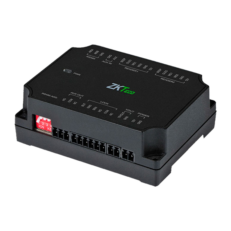
ZKTeco
ZKTeco DM10 quick start guide
