Rexroth Indramat DURADRIVE SYSTEM200 Technical manual

Project Planning Manual
DOK-DURADR-HDC01.1****-PR02-EN-P
SYSTEM200
DURADRIVE
Drive Controllers
with degree of protection IP 65

About this Documentation DURADRIVE Drive Controllers
DOK-DURADR-HDC01.1****-PR02-EN-P
DURADRIVE
Drive Controllers
with degree of protection IP 65
Project Planning Manual
DOK-DURADR-HDC01.1****-PR02-EN-P
•Document number: 120-0855-B301-02/EN
This documentation describes
•planning the mechanical construction
•planning the electrical
•logistical handling of the equipment
•preparing the necessary equipment for startup operation
Description Release
Date
Notes
DOK-DURADR-HDC01.1****-PR01-EN-P 01.01 1st edition
DOK-DURADR-HDC01.1****-PR02-EN-P 07.01 2nd edition
2001 Rexroth Indramat GmbH
Copying this document, giving it to others and the use or communication
of the contents thereof without express authority, are forbidden. Offenders
are liable for the payment of damages. All rights are reserved in the event
of the grant of a patent or the registration of a utility model or design
(DIN 34-1).
The specified data is for product description purposes only and may not
be deemed to be guaranteed unless expressly confirmed in the contract.
All rights are reserved with respect to the content of this documentation
and the availability of the product.
Rexroth Indramat GmbH
Bgm.-Dr.-Nebel-Str. 2 •D-97816 Lohr a. Main
Telephone 09352/40-0 •Tx 689421 •Fax 09352/40-4885
http://www.rexroth.com/indramat
Dept. ECD (RS/US/BB)
This document has been printed on chlorine-free bleached paper.
Title
Type of Documentation
Document Typecode
Internal File Reference
Purpose of Documentation
Record of Revisions
Copyright
Validity
Published by
Note

DURADRIVE Drive Controllers Contents I
DOK-DURADR-HDC01.1****-PR02-EN-P
Contents
1 Introduction to the system 1-1
1.1 DURADRIVE drive controller ......................................................................................................... 1-1
1.2 An overview of individual components of the DURADRIVE family................................................ 1-3
1.3 An overview of the drive controllers ............................................................................................... 1-4
Type code for drive controller HDC ......................................................................................... 1-4
Type code for cooling fan unit..................................................................................................1-4
An overview of the communications interfaces........................................................................ 1-5
An overview of measuring systems supported ........................................................................ 1-6
1.4 Overview of the motors .................................................................................................................. 1-7
MKD synchronous motor for standard applications................................................................. 1-7
MHD synchronous motors for high-precision applications ...................................................... 1-8
MKE synchronous motor for potentially explosive areas......................................................... 1-9
2AD asynchronous motor for standard applications................................................................ 1-9
ADF asynchronous motor for standard applications.............................................................. 1-10
1MB asynchronous assembly motor...................................................................................... 1-10
MBW asynchronous motor for printing roller applications ..................................................... 1-11
MBS synchronous assembly motor ....................................................................................... 1-11
LSF linear synchronous assembly motor............................................................................... 1-12
2 Important directions for use 2-1
2.1 Appropriate use.............................................................................................................................. 2-1
Introduction .............................................................................................................................. 2-1
Areas of use and application....................................................................................................2-2
2.2 Inappropriate use ........................................................................................................................... 2-2
3 Safety Instructions for Electric Servo Drives 3-1
3.1 Introduction..................................................................................................................................... 3-1
3.2 Explanations................................................................................................................................... 3-1
3.3 Hazards by inappropriate use ........................................................................................................ 3-2
3.4 General Information ....................................................................................................................... 3-3
3.5 Protection against contact with electrical parts.............................................................................. 3-4
3.6 Protection by protective low voltage (PELV) against electrical shock ........................................... 3-6
3.7 Protection against dangerous movements..................................................................................... 3-6
3.8 Protection against magnetic and electromagnetic fields during operations and mounting............ 3-8
3.9 Protection against contact with hot parts ....................................................................................... 3-9
3.10 Protection during handling and installation .................................................................................... 3-9
3.11 Battery safety ............................................................................................................................... 3-10
3.12 Protection against pressurized Systems......................................................................................3-10

II Contents DURADRIVE Drive Controllers
DOK-DURADR-HDC01.1****-PR02-EN-P
4 DURADRIVE HDC01.1 Drive Controller 4-1
4.1 Technical data................................................................................................................................ 4-1
Dimensions .............................................................................................................................. 4-1
Ambient and operating conditions ........................................................................................... 4-3
Electric Data of the Individual HDC01.1 Components............................................................. 4-6
Storable energy in the bus..................................................................................................... 4-14
Allowed DC bus peak power.................................................................................................. 4-16
Allowed DC bus continuous power ........................................................................................ 4-16
Sizing components relevant to regeneration ......................................................................... 4-18
CE label, C-UL listing, Tests.................................................................................................. 4-20
4.2 Electrical connections - independent of the drive controller type................................................. 4-21
A look at the drive controller and connector designations ..................................................... 4-21
Independent of the drive controller type – total connecting diagram..................................... 4-25
X1, Connections for Control voltage ...................................................................................... 4-26
X2, Serial interface................................................................................................................. 4-28
X3, Digital and analog I/Os .................................................................................................... 4-32
X4, Encoder 1 ........................................................................................................................ 4-38
X5, Motor connections, motor temperature monitoring and holding brake............................ 4-41
X7, Connection for programming module..............................................................................4-47
X8, Encoder 2 ........................................................................................................................ 4-49
X10, EcoXexpansion interface............................................................................................... 4-55
X11, Ready to operate contact Bb, activation power ON ...................................................... 4-56
X13, Mains connection...........................................................................................................4-61
X14, Ventilator connection ..................................................................................................... 4-61
XE1, Protective conductor connections for mains ................................................................. 4-63
XS1, XS2, XS3, XS4 shield connections ............................................................................... 4-64
4.3 Electrical connections – dependent on the drive controller type.................................................. 4-65
HDC01.1-***N-SE01-01-FW – SERCOS interface................................................................ 4-65
HDC01.1-***N-PB01-01-FW – Profibus-DP Interface ........................................................... 4-69
HDC01.1-***N-IB01-01-FW – InterBus Interface................................................................... 4-74
HDC01.1-***N-CN01-01-FW – CANopen Interface............................................................... 4-77
HDC01.1-***N-DN01-01-FW – DeviceNet Interface.............................................................. 4-79
HDC01.1-***N-SE02-01-FW – SERCOS interface 2............................................................. 4-81
5 DC24V NTM power supplies 5-1
5.1 Application recommendations........................................................................................................ 5-1
5.2 Technical data................................................................................................................................ 5-1
5.3 Dimensional sheets and installation dimensions ........................................................................... 5-2
5.4 Front views..................................................................................................................................... 5-2
5.5 Electrical connection ...................................................................................................................... 5-3
5.6 Type code....................................................................................................................................... 5-4
6 DST transformers 6-1
6.1 Selection......................................................................................................................................... 6-1
6.2 Autotransformers for Drive Controllers .......................................................................................... 6-1
6.3 Type code....................................................................................................................................... 6-4

DURADRIVE Drive Controllers Contents III
DOK-DURADR-HDC01.1****-PR02-EN-P
7 Mains Connections 7-1
7.1 General........................................................................................................................................... 7-1
7.2 Grounding conditions of the power supply network ....................................................................... 7-1
7.3 Earth-leakage circuit breaker ......................................................................................................... 7-2
7.4 Control circuits for the mains connection ....................................................................................... 7-2
Control circuits with E-Stop...................................................................................................... 7-3
7.5 Fuses.............................................................................................................................................. 7-5
Computing phase current on the mains................................................................................... 7-5
Computing charging current inrush.......................................................................................... 7-5
Factor F for computing the connected load ............................................................................. 7-6
Selecting fusing Q1.................................................................................................................. 7-7
8 Constructing the control cabinet 8-1
8.1 Power dissipation ........................................................................................................................... 8-1
8.2 General notes................................................................................................................................. 8-7
8.3 Wire routing in the cable duct ........................................................................................................ 8-8
9 State of Delivery of the Drive Components 9-1
9.1 Packaging....................................................................................................................................... 9-1
9.2 Papers............................................................................................................................................ 9-2
9.3 Extent of Delivery........................................................................................................................... 9-2
9.4 Ordering ......................................................................................................................................... 9-3
Replacement Parts .................................................................................................................. 9-3
Additional Accessories............................................................................................................. 9-3
Mounting Accessories.............................................................................................................. 9-3
Commissioning Aids ................................................................................................................ 9-3
10 Identifying the Components 10-1
10.1 Component designations ............................................................................................................. 10-1
Type Plates ............................................................................................................................ 10-2
11 Replacing or Exchanging Drive Components 11-1
11.1 General......................................................................................................................................... 11-1
11.2 Procedure on Replacing the Unit ................................................................................................. 11-3
Replacing the drive controller: ...............................................................................................11-3
Replacing the cooling fan unit................................................................................................ 11-4
Replacing the Motor............................................................................................................... 11-6
Replacing cables.................................................................................................................... 11-6
11.3 Replacing Firmware ..................................................................................................................... 11-9
Replacing the Parameter Module .......................................................................................... 11-9
Replacing the Firmware Module .......................................................................................... 11-10
Replacing the Programming Module (complete module) .................................................... 11-10
12 Attachment 12-1
12.1 Wire routing and wiring of the drive controller.............................................................................. 12-1
RS485 connector ................................................................................................................... 12-2

IV Contents DURADRIVE Drive Controllers
DOK-DURADR-HDC01.1****-PR02-EN-P
12.2 What is needed to prepare to start-up ......................................................................................... 12-3
12.3 Signal sequence HDC01.1........................................................................................................... 12-4
Recommended switching on sequence................................................................................. 12-4
Recommended off sequence................................................................................................. 12-6
12.4 Cleaning the drive controller ........................................................................................................ 12-8
12.5 Directory of standards and guidelines.......................................................................................... 12-9
13 Index 13-1
14 Service & Support 14-1
14.1 Helpdesk ...................................................................................................................................... 14-1
14.2 Service-Hotline............................................................................................................................. 14-1
14.3 Internet ......................................................................................................................................... 14-1
14.4 Vor der Kontaktaufnahme... - Before contacting us..................................................................... 14-1
14.5 Kundenbetreuungsstellen - Sales & Service Facilities ................................................................ 14-2

DURADRIVE Drive Controllers Introduction to the system 1-1
DOK-DURADR-HDC01.1****-PR02-EN-P
1 Introduction to the system
1.1 DURADRIVE drive controller
PZ5015F1.FH7
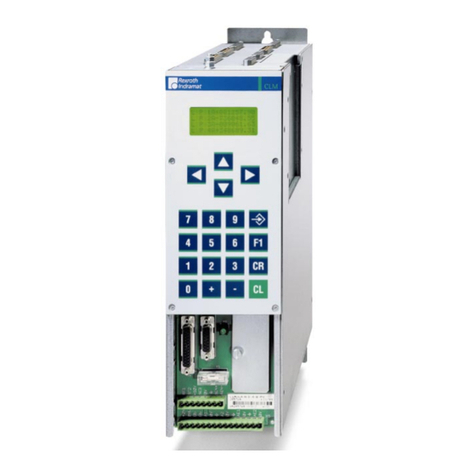
Fig. 1-1: DURADRIVE drive controller
The digital intelligent automation system DURADRIVE is the solution with
a high degree of functionality for stand-alone drives under difficult ambient
conditions.
DURADRIVE can be used to implement a variety of drive tasks in the
most varied applications. Different device types are available with
graduated drive power.

1-2 Introduction to the system DURADRIVE Drive Controllers
DOK-DURADR-HDC01.1****-PR02-EN-P
Typical application areas are:
•handling systems
•packaging machines
•assembly systems
•printing machines
•machine tools

DURADRIVE Drive Controllers Introduction to the system 1-3
DOK-DURADR-HDC01.1****-PR02-EN-P
1.2 An overview of individual components of the DURADRIVE
family
FA5126F1.FH7
HDC
NFE
NTM
Control voltage supply unit
Line filter for control
voltage supply unit
Drive controller
FWA
Firmware
IKS - ready-made feedback cable
AC motor
Components shown in gray are absolutely necessary.
System voltage
DC 24 V
IKG - ready-made power cable
IKL - ready-made power cable
Fig. 1-2: Overview of individual components

1-4 Introduction to the system DURADRIVE Drive Controllers
DOK-DURADR-HDC01.1****-PR02-EN-P
1.3 An overview of the drive controllers
Type code for drive controller HDC
HDC 01.1 - A040N - PB01 - 01 - FW
Line 01
Product group HDC
Type code fields: Example:
Special design
none N
Rated current
40 A 040
100 A 100
200 A 200
Design 1
TL0214F1.FH7
Cooling mode
natural convection (heatsink
outside) A
Firmware FW
denotes that firmware must be ordered as separate
subposition = FW
Interface
CANopen interface CN01
DeviceNet interface DN01
InterBus interface IB01
Profibus-DP interface PB01
SERCOS interface SE01
SERCOS interface 2 SE02
Version of the interface 01
Fig. 1-3: Type code HDC
Type code for cooling fan unit
Class: Drive controller HDC H
Product: Cooling fan unit for controllers LEC
Other design
none N
TL0216F1.FH7
LECH - 040N
Type code fields: Example:
Rated current for drive controller
40 A 040
100 A, 200 A 200
Fig. 1-4: Type code cooling fan unit
Note: The above illustrates how the type codes are put together.
Your Sales rep will help with the current status of available
versions.

DURADRIVE Drive Controllers Introduction to the system 1-5
DOK-DURADR-HDC01.1****-PR02-EN-P
An overview of the communications interfaces
device type:
CN01 DN01 IB01 PB01 PL02 SE01 SE02
interface
RS232 / 485 XXXXXXX
CANopen interface X
DeviceNet interface X
InterBus interface X
Profibus-DP interface X
SERCOS interface X
SERCOS interface 2 X
Fig. 1-5: An overview of interfaces
Note: Parallel interface 2 is only required in combination with the
ELC control software.

1-6 Introduction to the system DURADRIVE Drive Controllers
DOK-DURADR-HDC01.1****-PR02-EN-P
An overview of measuring systems supported
Connecting the systems to the encoder inputs
Encoder 1 (plug X4) Encoder 2 (plug X8)
Digital
servo-
feedback
(1)
Type of
motor
DSF HSF
Resolver with
FDS
(2)
Resolver
without FDS
(3)
Sine encoder
(4)
EnDat
encoder
(5)
Gear-type
encoder with
1Vss signals
(6)
Square-wave
encoder with
5V TTL signals
(7)
MKD XX
MKE XX
MHD X
2AD XX X *)
ADF XX X *)
1MB XX XX
*)
MBW XX XX
*)
LSF X
MBS XXX
Fig. 1-6: Connecting the measuring systems
(1) : single-turn or multi-turn DSF / HSF
(2) : resolver or multi-turn resolver (RSF) with
feedback data storage (FDS)
(3) : resolver or multi-turn resolver (RSF) without
feedback data storage (FDS)
(4) : incremental measuring system with sine signals
(1Vss signals)
(5) : absolute measuring system with EnDat interface
(6) : gear-type encoder with 1Vss signals
(7) : square-wave encoder with 5V TTL signals
-> *) not recommended (due to maximum input frequency
of 200 kHz)!
Note: The cable type designations of the connecting cables required
are listed in the motor project planning manual or "List of
Connecting Cables for DIAX04 and ECODRIVE03".
See also the firmware functional description: "Setting the Measurement
System".

DURADRIVE Drive Controllers Introduction to the system 1-7
DOK-DURADR-HDC01.1****-PR02-EN-P
1.4 Overview of the motors
MKD synchronous motor for standard applications
•general automation technology
•handling systems
•axes that only need to approach fixed positions (no path operation)
•applications with low-precision demands (accuracy of up to
approx. 1/20000 of one motor revolution)
•motor in a chassis configuration
•motor cooling method:natural convection
surface cooling is optional for the MKD112
Fig. 1-7: An MKD motor
Application
Construction

1-8 Introduction to the system DURADRIVE Drive Controllers
DOK-DURADR-HDC01.1****-PR02-EN-P
MHD synchronous motors for high-precision applications
•Automated production with the highest demands for accuracy (up to
1/4000000 of a motor revolution)
•high demands on dynamics
•axes in path operation
•Motor in a chassis configuration
•Motor cooling method:natural convection
surface cooling is optional for the MHD093, MHD112, MHD115
liquid cooling is optional for the MHD093, MHD115
Fig. 1-8: An MHD motor
Application
Construction

DURADRIVE Drive Controllers Introduction to the system 1-9
DOK-DURADR-HDC01.1****-PR02-EN-P
MKE synchronous motor for potentially explosive areas
•potentially explosive areas such as: painting installations, chemical
industries in general automation engineering
•applications with low-precision demands (accuracy of up to
approx. 1/20000 of one motor revolution)
•motor in a chassis configuration
•motor cooling method: natural convection
Fig. 1-9: An MKE motor
2AD asynchronous motor for standard applications
•main spindle and servo axes in machine tools for drive tasks with high
performance demands
•highest demands on accuracy (up to 1/2000000 of a motor revolution)
•axes in path operation
•motor in a chassis configuration
•motor cooling method: surface cooled
Fig. 1-10: An 2AD motor
Application
Construction
Application
Construction

1-10 Introduction to the system DURADRIVE Drive Controllers
DOK-DURADR-HDC01.1****-PR02-EN-P
ADF asynchronous motor for standard applications
•main spindle and servo axes in machine tools for drive tasks with high
performance demands
•highest demands on accuracy (up to 1/2000000 of a motor revolution
possible)
•axes in path operation
•motor in a chassis configuration
•motor cooling method: liquid cooled
Fig. 1-11: An ADF motor
1MB asynchronous assembly motor
•compact machine concepts for main spindles and servo axes in
lathes, milling machines, grinding machines and processing centers
•for main spindles in high-speed processing
•for drive tasks with high performance demands
•highest demands on accuracy (up to 1/4000000 of a motor revolution
possible)
•axes in path operation
•motor as assembly kit for integration into the machine components
•motor cooling method: liquid cooled
Fig. 1-12: An 1MB motor
Application
Construction
Application
Construction

DURADRIVE Drive Controllers Introduction to the system 1-11
DOK-DURADR-HDC01.1****-PR02-EN-P
MBW asynchronous motor for printing roller applications
•for printing roller applications with high demands for accuracy
•motor for mounting directly onto the printing roller
•motor cooling method: liquid cooled
Fig. 1-13: An MBW motor
MBS synchronous assembly motor
•compact machine concepts for main spindles and servo axes in
lathes, milling machines, grinding machines and processing centers
•for main spindles in high-speed processing
•highest demands on accuracy
•motor as assembly kit for integration into machine components
•motor cooling method: liquid cooled
Fig. 1-14: An MBS motor
Application
Construction
Application
Construction

1-12 Introduction to the system DURADRIVE Drive Controllers
DOK-DURADR-HDC01.1****-PR02-EN-P
LSF linear synchronous assembly motor
•For precision applications in new compact machine concepts for main
spindles and servo axes in lathes, milling machines, grinding
machines and processing centers for use in high-speed processing
•machine concepts in printing, packaging, and sheet metal processing
machines
•highest demands on accuracy (less than 0.5 µm possible)
•motor as assembly kit for integration into machine components
•motor cooling method: liquid cooled
Fig. 1-15: An LSF motor
Application
Construction

DURADRIVE Drive Controllers Important directions for use 2-1
DOK-DURADR-HDC01.1****-PR02-EN-P
2 Important directions for use
2.1 Appropriate use
Introduction
Rexroth Indramat products represent state-of-the-art developments and
manufacturing. They are tested prior to delivery to ensure operating safety
and reliability.
The products may only be used in the manner that is defined as
appropriate. If they are used in an inappropriate manner, then situations
can develop that may lead to property damage or injury to personnel.
Note: Rexroth Indramat, as manufacturer, is not liable for any
damages resulting from inappropriate use. In such cases, the
guarantee and the right to payment of damages resulting from
inappropriate use are forfeited. The user alone carries all
responsibility of the risks.
Before using Rexroth Indramat products, make sure that all the pre-
requisites for an appropriate use of the products are satisfied:
•Personnel that in any way, shape or form uses our products must first
read and understand the relevant safety instructions and be familiar
with appropriate use.
•If the product takes the form of hardware, then they must remain in
their original state, in other words, no structural changes are permitted.
It is not permitted to decompile software products or alter source
codes.
•Do not mount damaged or faulty products or use them in operation.
•Make sure that the products have been installed in the manner
described in the relevant documentation.

2-2 Important directions for use DURADRIVE Drive Controllers
DOK-DURADR-HDC01.1****-PR02-EN-P
Areas of use and application
Drive controllers made by Rexroth Indramat are designed to control
electrical motors and monitor their operation.
Control and monitoring of the motors may require additional sensors and
actors.
Note: The drive controllers may only be used with the accessories
and parts specified in this document. If a component has not
been specifically named, then it may not be either mounted or
connected. The same applies to cables and lines.
Operation is only permitted in the specified configurations and
combinations of components using the software and firmware
as specified in the relevant function descriptions.
Every drive controller has to be programmed before starting it up, making
it possible for the motor to execute the specific functions of an application.
The drive controllers of the ECODRIVE03 family are designed for use in
single or multiple-axis drive and control applications.
To ensure an application-specific use, the drive controllers are available
with differing drive power and different interfaces.
Typical applications of drive controllers belonging to the ECODRIVE03
family are:
•handling and mounting systems,
•packaging and foodstuff machines,
•printing and paper processing machines and
•machine tools.
The drive controllers may only be operated under the assembly,
installation and ambient conditions as described here (temperature,
system of protection, humidity, EMC requirements, etc.) and in the
position specified.
2.2 Inappropriate use
Using the drive controllers outside of the above-referenced areas of
application or under operating conditions other than described in the
document and the technical data specified is defined as “inappropriate
use".
Drive controllers may not be used if
•they are subject to operating conditions that do not meet the above
specified ambient conditions. This includes, for example, operation
under water, in the case of extreme temperature fluctuations or
extremely high maximum temperatures or if
•Rexroth Indramat has not specifically released them for that intended
purpose. Please note the specifications outlined in the general safety
instructions!
Other manuals for DURADRIVE SYSTEM200
1
Table of contents
Other Rexroth Indramat Controllers manuals