Prizmatix UHP-T Series User manual
Main Office
Phone: +972-72-2500097
Fax: +972-72-2500096
sales@prizmatix.com
European Sales Office
Phone: +44-(0)77-9172-9592
Fax: +44-(0)20-7681-2977
sales.europe@prizmatix.com
North America Sales Office
Phone: +1-(248)-436-8085
Fax: +1-(248)-281-5236
sales.usa@prizmatix.com
P.O.B . 244 Givat -S hmu el 541 01, Is rael
UHP-T
LED Illuminator with
UHPTLCC-02-USB
Controller
User Manual
Ver 1.0

Prizmatix
2 | P a g e UHP-T-LED with UHPTLCC-02-USB User Manual
Contents
1 Introduction ................................................................................................................3
1.1 Features................................................................................................................3
1.2 Intended use.........................................................................................................3
2 Safety...........................................................................................................................3
2.1 General safety.......................................................................................................3
2.2 Eye safety..............................................................................................................4
2.2.1 UHP-T illuminator assignment according to IEC 62471 ................................4
2.2.2 Special safety notes.......................................................................................6
2.2.3 Hazard Distances (HD)...................................................................................7
2.2.4 Permissible exposure duration (tmax) ............................................................7
3 Setup of the device .....................................................................................................8
3.1 Package contents list ............................................................................................8
3.2 System overview:..................................................................................................9
3.3 UHP-T illuminator system connection................................................................10
3.4 Use of UHP-T LED illuminator on a microscope .................................................12
3.4.1 Setting of the illuminator LED head on the microscope.............................12
3.4.2 Illuminator alignment on the microscope................................................... 13
3.4.3 Disconnection of illuminator LED head from a microscope .......................14
3.5 Use of UHP-T LED illuminator for table-top illumination...................................14
3.6 LED Control by TTL Input ....................................................................................14
3.7 Computer Control and Power Monitoring .........................................................15
4 Cleaning.....................................................................................................................15
5 Specifications ............................................................................................................16
5.1 Electrical specifications ......................................................................................16
5.2 General specifications ........................................................................................16

Prizmatix
3 | P a g e UHP-T-LED with UHPTLCC-02-USB User Manual
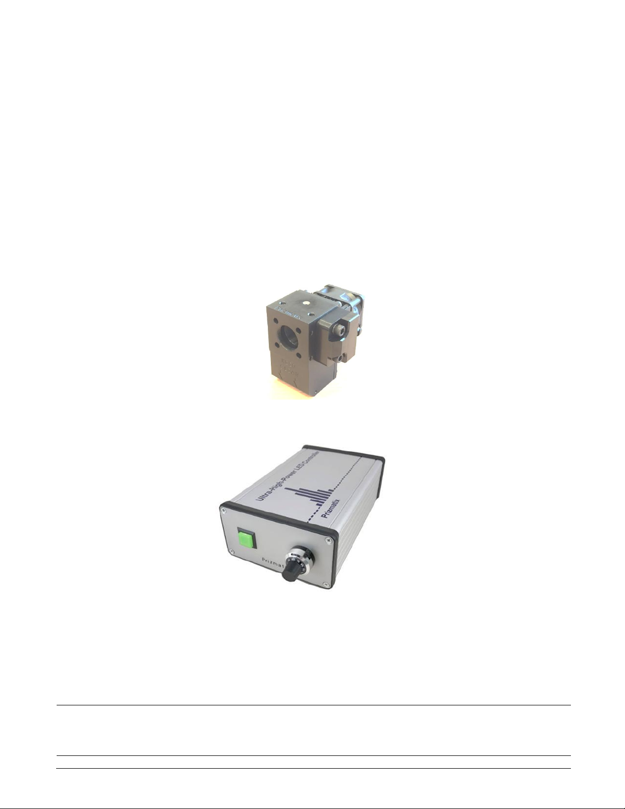
1 Introduction
The UHP-T-LED is an Ultra High Power LED light source for various laboratory applications
including fluorescence microscopy, Optogenetics, high power illumination and other applications.
It is an effective replacement for spectral lamps and lasers.
The UHPTLCC-02-USB current controller supports CW operation, TTL triggering and
synchronization, control from computer via USB interface and logging of output power into
computer if optional photo-receiver is installed.
1.1 Features
•Compatible with Prizmatix modular UHP-T-LED, UHP‐Mic-LED and Mic-LED Light-
Source products families –for creation of multi-wavelength setups for Fluorescence
microscopy, Optogenetics, fiberoptic applications and more.
•Single chip Ultra High Brightness LED (Except UHP-T-LA product line).
•Optically isolated TTL input for external triggering (no shutter needed).
•LED spectrum can be narrowed by band pass filters or a filter wheel.
•Computer control via USB.
•Excellent for fluorescence excitation
•Stable precisely adjustable power
•Long life (no lamp or laser tube replacement required)
•Rapid warm up time
1.2 Intended use
The UHP-T-LED is an Ultra-High-Power LED light source designed to be used in various scientific
applications in laboratory. Few examples of use are fluorescence microscopy, whole body imaging
of small animals, bio-analysis, photo-activation and numerous others.
2 Safety
2.1 General safety
Please make yourself familiar with the contents of these operating instructions before using the
UHP-T-LED system. Use the illuminator only as specified in this manual. Otherwise, the protection
provided by the illuminator may be impaired.
The following symbols are used for the warnings:
CAUTION! Failure to comply with the safety instructions can be hazardous to the user.
CAUTION! Failure to comply with the safety instructions can result in damage to the
instrument.
Prizmatix
4 | P a g e UHP-T-LED with UHPTLCC-02-USB User Manual
Do not use the illuminator if it is damaged. Before you use the illuminator, inspect the case. Look
for cracks or missing parts.
Do not use the device around explosive gas.
Never operate the illuminator with the controller cover removed or the case open.
Any maintenance should ONLY be performed by a Prizmatix authorized technician.
Prizmatix products are NOT authorized for use as components in life support devices or systems.
2.2 Eye safety
The UHP-T illuminator system is in excess of the Exempt Group. The viewer-related risk is highly
dependent upon the use and installation of the product. For example if the product is attached to
epifluorescence port of microscope the beam is restricted and in most case such system will be
assigned to a Low Risk or Exempt Group, on the contrary if the illuminator is used for table top
illumination of a Petri dish –such assembly may be of potentially High Risk Group. Each specific
setup shall be evaluated and assigned to an appropriate risk group by the user and appropriate
safety means should be taken. Herein below a free space unrestricted setup is analyzed and various
models of UHP-T illuminators are assigned to appropriate Risk Groups. This assignment is a worst-
case analysis.
2.2.1 UHP-T illuminator assignment according to IEC 62471
The UHP-T illuminator is assigned to following risk groups according to IEC 62471: 2006. The
assignment done based on the standard system configuration for table-top illumination. The
assignment results are summarized in Table 1.
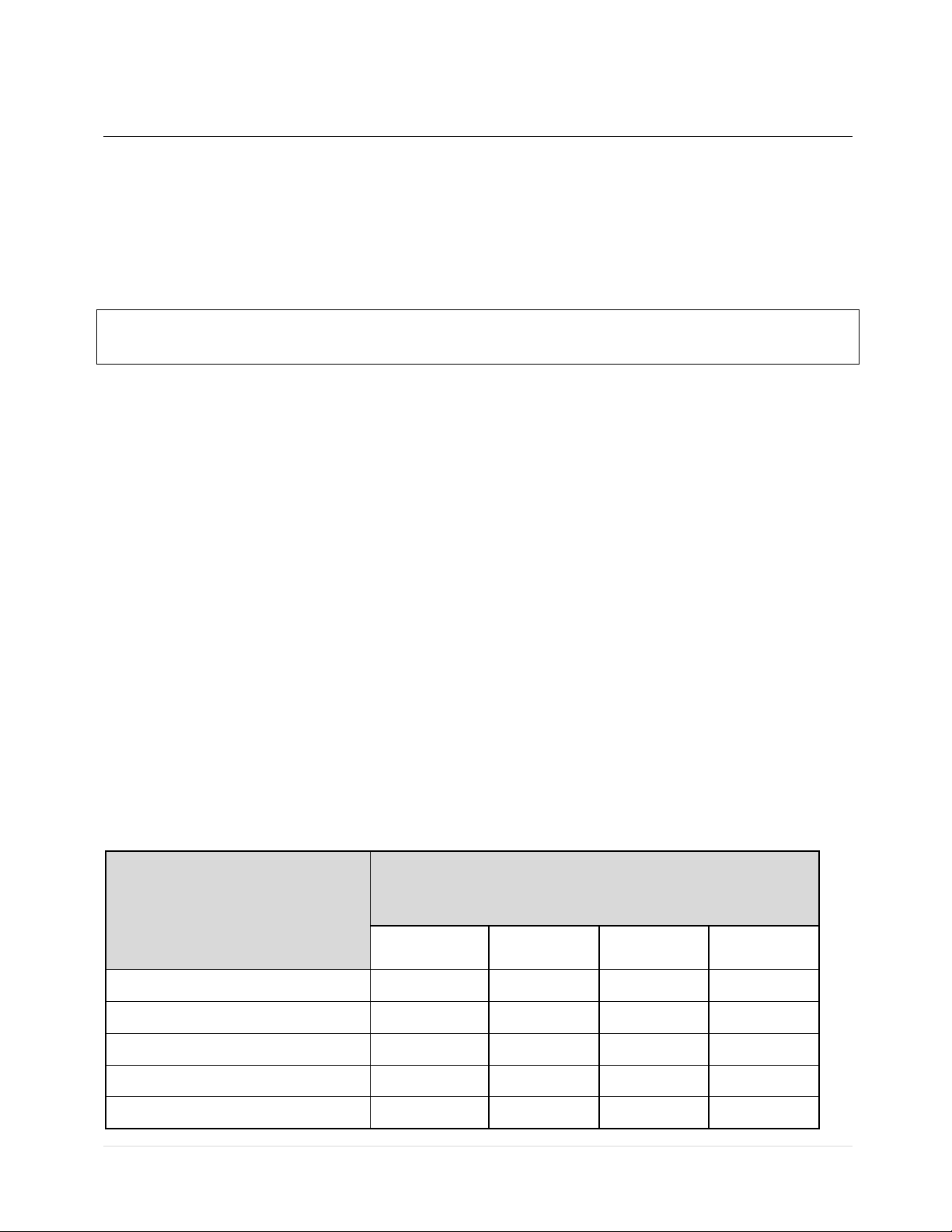
Table 1: UHP-T illuminator assignment to risk groups according to IEC 62471: 2006.
Product Type
Assignment to
Risk Group
Exempt
RG0
Low Risk
RG1
Mod Risk
RG2
High Risk
RG3
UHP-T-405-EP
UHP-T-455-EP
UHP-T-520-EP
UHP-T-625-EP
UHP-T-White

Prizmatix
5 | P a g e UHP-T-LED with UHPTLCC-02-USB User Manual
The UHP-T illuminators are marked on the product with following labels:
Product
Safety Label
UHP-T-405-EP
RISK GROUP 3
WARNING UV emitted from this product.
WARNING Possibly hazardous optical radiation
emitted from this product
UHP-T-455-EP
RISK GROUP 3
WARNING Possibly hazardous optical radiation
emitted from this product
CAUTION Possibly hazardous optical radiation
emitted from this product
NOTICE UV emitted from this product
UHP-T-520-EP
RISK GROUP 2
CAUTION Possibly hazardous optical radiation
emitted from this product
UHP-T-625-EP
Not required
UHP-T-White
RISK GROUP 2
CAUTION. Possibly hazardous optical
radiation emitted from this product.

Prizmatix
6 | P a g e UHP-T-LED with UHPTLCC-02-USB User Manual
2.2.2 Special safety notes
Table 2 summarize the safety notes specific to various product types (IEC/TR 62471-2, 2009 Tables
1 and 2).
Table 2: Safety labels specific to various product types
Product
Safety Label
UHP-T-405-EP
RISK GROUP 3
WARNING. UV emitted from this product.
Avoid eye and skin exposure to unshielded product
CAUTION. UV emitted from this product. Eye or skin
irritation may result from exposure. Use appropriate
shielding.
CAUTION. Possibly hazardous optical radiation emitted
from this product. Do not stare at operating lamp. May be
harmful to the eyes.
WARNING. Possibly hazardous optical radiation emitted
from this product. Do not look at operating lamp. Eye
injury may result.
UHP-T-455-EP
RISK GROUP 3
WARNING. Possibly hazardous optical radiation emitted
from this product. Do not look at operating lamp. Eye
injury may result.
CAUTION. Possibly hazardous optical radiation emitted
from this product. Do not stare at operating lamp. May be
harmful to the eyes.
NOTICE UV emitted from this product. Minimize exposure
to eyes and skin. Use appropriate shielding.
UHP-T-520-EP
RISK GROUP 2
CAUTION. Possibly hazardous optical radiation emitted
from this product. Do not stare at operating lamp. May be
harmful to the eyes.
UHP-T-625-EP
Not required
UHP-T-White
Risk Group 2
CAUTION. Possibly hazardous optical radiation emitted
from this product. Do not stare at operating lamp. May be
harmful to the eyes.

Prizmatix
7 | P a g e UHP-T-LED with UHPTLCC-02-USB User Manual
2.2.3 Hazard Distances (HD)
Following Table 3 provides the distance from distal end of the fiber at which the threshold
illuminance EL returns the product to RG 1.
Table 3: Distances from distal end of the fiber at which the photochemical hazard reduces to Risk
group 1, for relevant products.
Product
Distance at which Blue-Light hazard reduced to Risk Group 1
[m]
UHP-T-405
8.0
UHP-T-455
11.5
UHP-T-520
2.4
UHP-T-625
Already within RG1 at 0.2m
UHP-T-White
4.4
2.2.4 Permissible exposure duration (tmax)
The Permissible Exposure Durations for UHP-T product are calculated and reported in Table 4 below
Table 4: Permissible Exposure Durations for UHP-T product.
Product
Radiance
tmax
[W·m-2·sr-1]
[sec]
UHP-T-405-EP
1.597E+05
6
UHP-T-455-EP
3.242E+05
3
UHP-T-520-EP
1.336E+04
75
UHP-T-625-EP
1.450E+02
6895
UHP-T-White
4.701E+04
21
Prizmatix
8 | P a g e UHP-T-LED with UHPTLCC-02-USB User Manual
3 Setup of the device
Remove the device from the packaging and inspect the device for loose components or any signs of
damage. Notify Prizmatix if the device appears damaged in any way: do not install or operate a
damaged device.
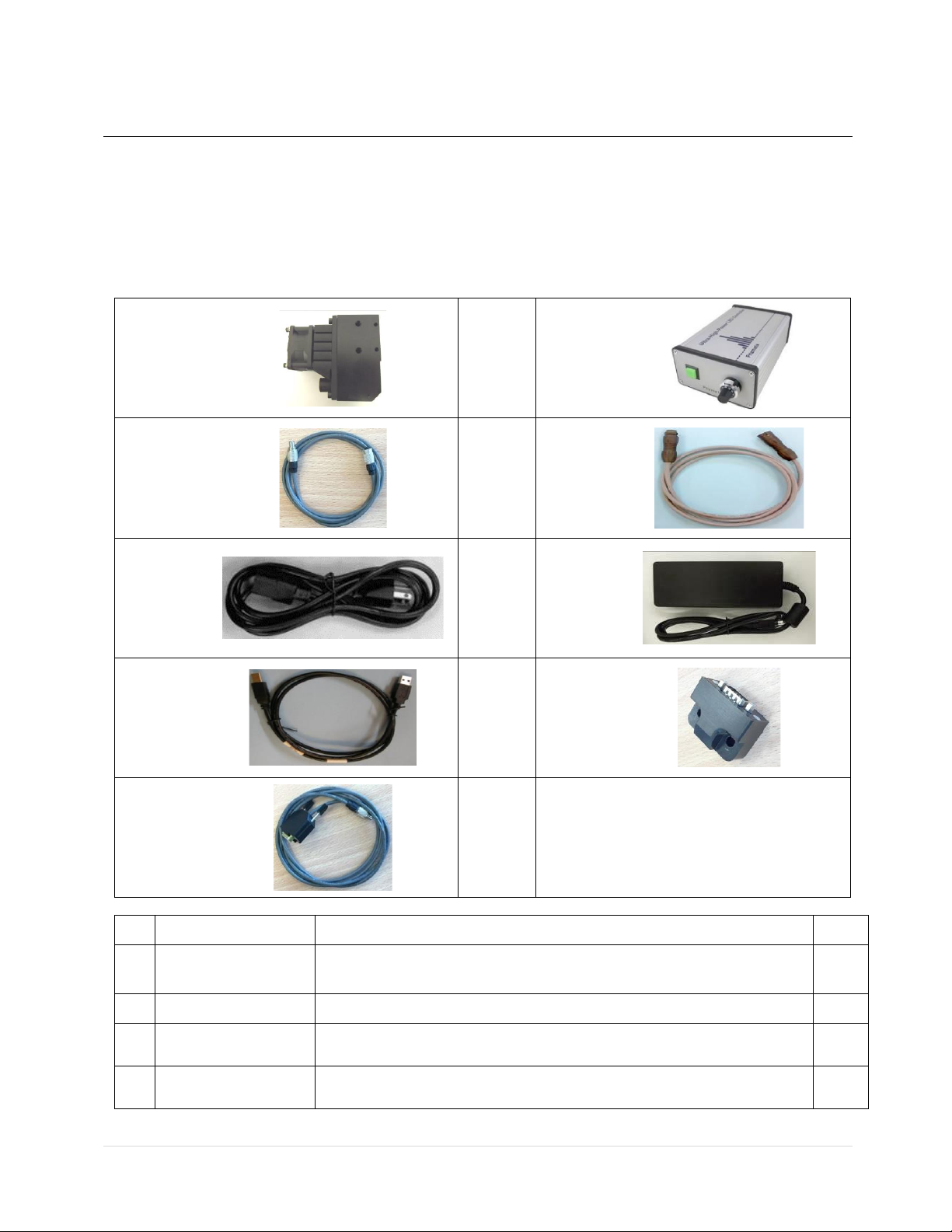
3.1 Package contents list
(1)
(2)
(3)
(4)
(5)
(6)
(7)
(8)
(9)
#
Item
Description
QTY
1
UHP-T-LED Head
UHP-T-LED head, with Olympus / Zeiss / Nikon / Leica microscope
adaptor assembled on it (optional).
1
2
UHPTLCC-02-USB
UHP-T-LED Benchtop Current Controller with USB connection
1
3
LED Control Cable
Cable to connect the UHP-T-LED to Controller
(4 pin connectors)
1
4
LED Current Cable
Cable to connect the UHP-T-LED to Controller
(3 pin connectors)
1
Prizmatix
9 | P a g e UHP-T-LED with UHPTLCC-02-USB User Manual
5
Mains Power Cord
Cord to connect the power adaptor to mains voltage
1
6
Power Adaptor
Universal power adaptor
1
7
USB Cable
USB-A to USB-B Cable
1
8
PD-LT Photosensor
Photosensor for power monitoring at computer. Typically, this item
will be assembled on UHP-T-LED head. Optional item.
1
9
Photosensor cable
Cable to connect the photosensor to the UHPTLCC-02-USB
controller. Optional item.
1
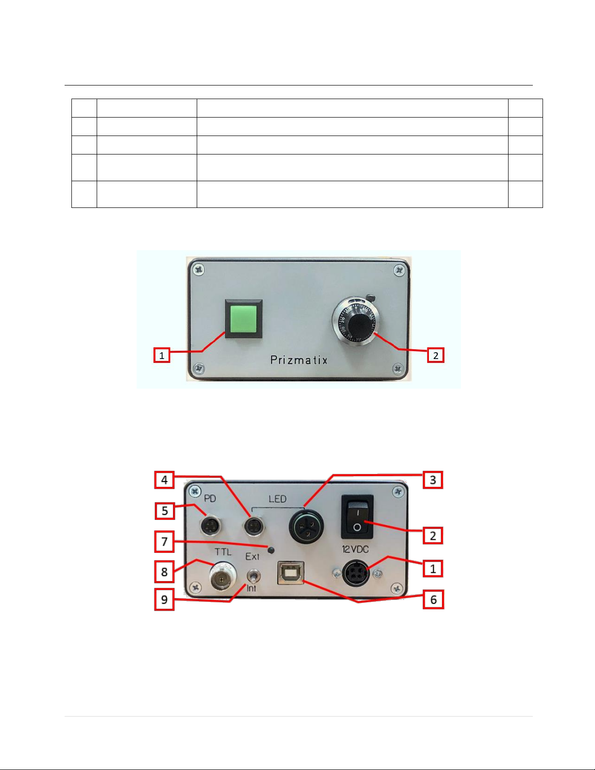
3.2 System overview:
Figure 1: Front panel of UHPTLCC-02-USB Current Controller: (1) LED light On/Off switch with
internal LED indicator, (2) Power adjustment dial (10-turn potentiometer).
Figure 2: UHPTLCC-02-USB LED Current Controller - back panel: (1) 12V DC power jack, (2) Power
On/Off switch, (3) LED current cable connector (3 contacts) , (4) LED control cable connector (4
contacts), (5) Photosensor connector (5 contacts), (6) USB connector, (7) Indicator LED, (8) TTL
input connector, (9) TTL-enable toggle switch.
Prizmatix
10 | P a g e UHP-T-LED with UHPTLCC-02-USB User Manual
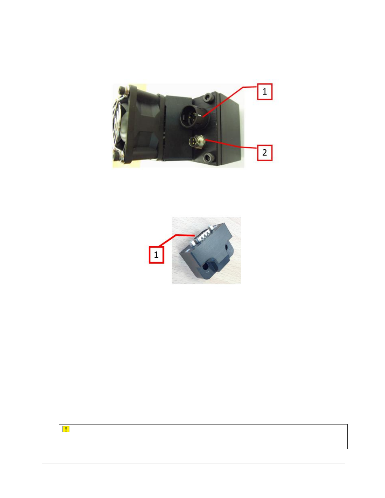
Figure 3: UHP-T LED illuminator head: (1) Connector for LED current cable, (2) Connector for LED
control cable
Figure 3a: PD-LT photosensor installed on the UHP-T-LED head: (1) D-Type 9-pin Connector for
PD-LT cable (This item is optional)
3.3 UHP-T illuminator system connection
1. Check that power On/Off switch on back panel is in OFF position.
2. Check that LED light On/Off button on front panel of UHPTLCC-02-USB current controller is
in Off position (pulled out position).
3. Turn the LED power adjustment dial on the front panel of the current controller
counterclockwise to the lowest setting.
4. Connect the LED Control Cable and the LED Current Cable to the UHPTLCC-02-USB LED
current controller and to the UHP-T-LED head (See Figure 4 and 5 below).
CAUTION!: Both metal and plastic connectors have a key to prevent mating in incorrect
orientation. Pay attention to connect the connectors correctly. Do not use excessive force!
Prizmatix
11 | P a g e UHP-T-LED with UHPTLCC-02-USB User Manual
5. Connect the PD-LT Photosensor Cable to the UHPTLCC-02-USB current controller (if you
ordered the photosensor).
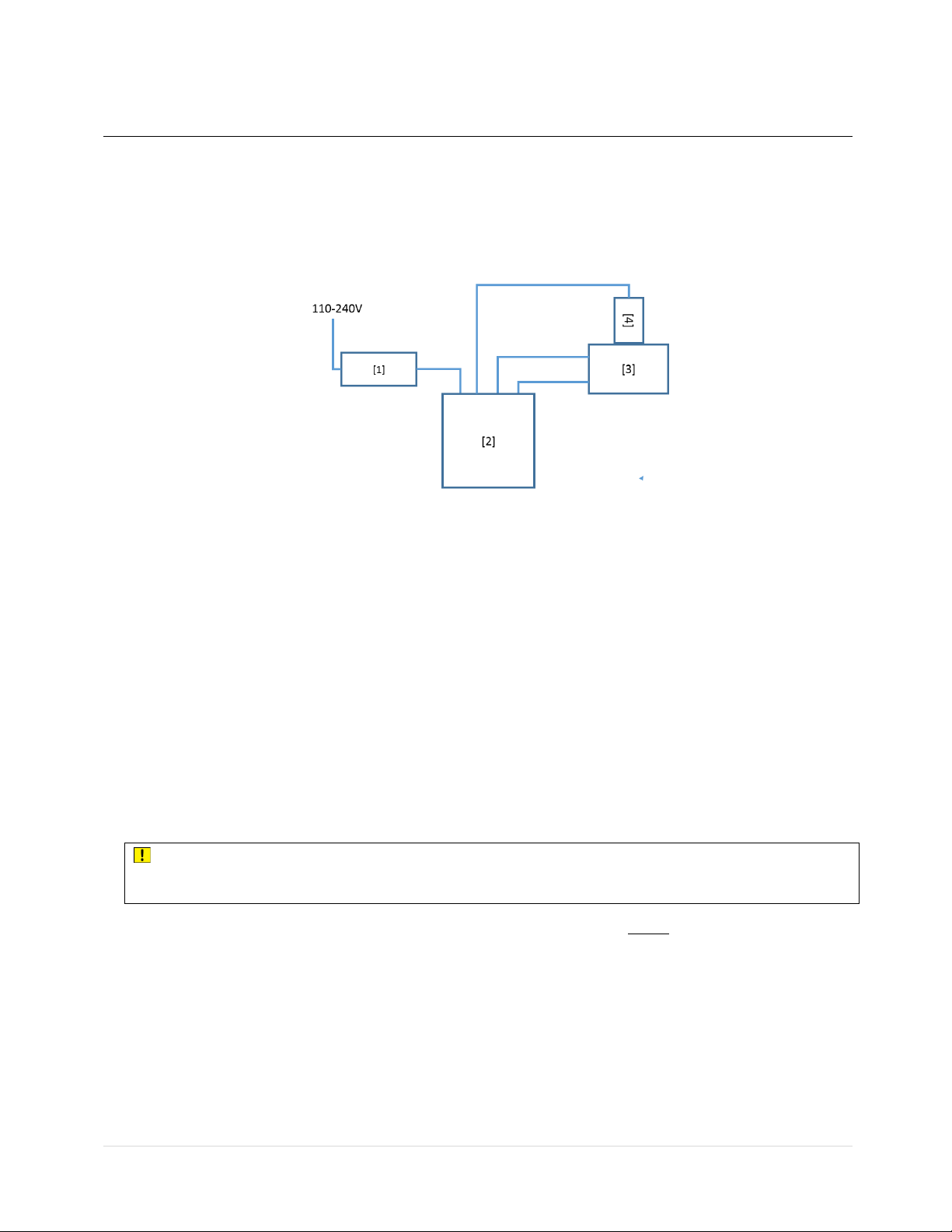
Figure 4: UHP-T LED Illuminator cable connection: (1) Power Adaptor, (2) UHPTLCC-02-USB
controller, (3) UHP-T-LED head, (4) PD-LT Photosensor
5. Connect the Power Adaptor cord to the 12VDC jack on the back panel of the Current
Controller.
6. Connect the Mains Power Cord to the Power Adaptor.
7. Plug the Power Adaptor into the wall outlet with the Mains Power Cord.
8. Switch the Int / Ext toggle switches at the back panel of current controller to Int position.
9. Switch the Power Switch on back panel to ON position.
10. Push the LED button on the front panel (LED emission switch). The button will light up.
11. Adjust the dial control to the desired output power level.
CAUTION!: Never disconnect the power cord form the product before switching the
ON/OFF switch on back panel to OFF position
Note: The LED button’s indicator on the front panel will turn ON, ONLY if the two cables from
LED head to controller are connected (i.e. Current cable and Control Cable).
Note: The LED head contains a thermistor to regulate the temperature of the LED. The fan is
activated only once the LED begins to warm up. When the LED is switched on from a cold
state at the maximum power setting the fan will start to work after 5 - 30 seconds, depending
on the LED wavelength and operation conditions.
Prizmatix
12 | P a g e UHP-T-LED with UHPTLCC-02-USB User Manual
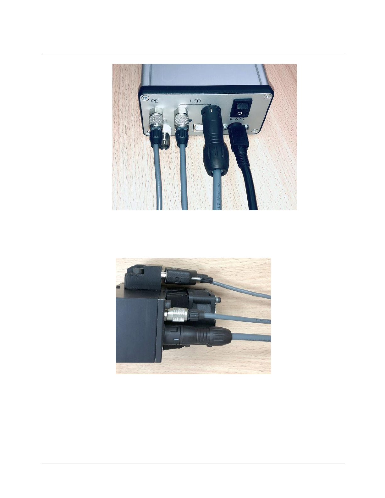
Figure 5a: Cable connections on the back panel of the UHPTLCC-02-USB current controller.
Remark: PD-LT Photosensor Cable has 5 pin metal connector; LED Control Cable has 4 pin metal
connector.
Figure 5b: Cable connections on the UHP-T-LED head
3.4 Use of UHP-T LED illuminator on a microscope
3.4.1 Setting of the illuminator LED head on the microscope
1. The UHP-T-LED is designed to fit into the fluorescence lamp port of a microscope by using
appropriate microscope adaptors.
Prizmatix
13 | P a g e UHP-T-LED with UHPTLCC-02-USB User Manual
2. Dismantle any existing fluorescence lamp (Hg, Xenon, etc.) from the microscope: most
microscope manufacturers (Zeiss, Olympus, Leica) use set screws to tighten the lamp onto
the port. Release the screws and carefully pull out the lamp. In the case of Nikon
microscopes with an F-mount, turn the grooved collar counterclockwise and release the
lamp.
3. Carefully insert the UHP-T-LED into the lamp port. Ensure the Z-adjustment screw is
accessible and tighten the set screws (or collar in Nikon microscopes).
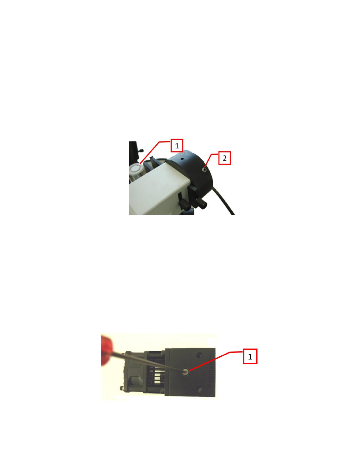
4. Observe the illumination. If needed adjust the UHP-T-LED axial focus by a Hex Key (2mm or
5/64")
Figure 6: Olympus microscope epi-fluorescence lamp port: (1) Olympus hex screw driver, (2)
Light source fixation set screws.
3.4.2 Illuminator alignment on the microscope
Z -alignment of the collimator lens is required to optimize the illumination provided by the UHP-T
LED illuminator.
Adjustment of the Z placement of the collimating lens relative to the LED chip is done by slightly
turning the Z-Adjust screw on the top of the UHP-T LED head (see Figure 7 below).
Note that the span of the screw motion is less than one full turn –this covers the full Z adjustment
move.
Figure 6: Z-Axis Focus Adjust: (1) Focus adjust screw

Prizmatix
14 | P a g e UHP-T-LED with UHPTLCC-02-USB User Manual
3.4.3 Disconnection of illuminator LED head from a microscope
1. Turn the power OFF and disconnect the cables from the LED head.
2. Loosen the two fixing set screws (or the F-mount collar on Nikon).
3. Pull out the UHP-T-LED head to disengage it from the microscope.
3.5 Use of UHP-T LED illuminator for table-top illumination
In case the UHP-T illuminator is used for table-top application as illumination of Petri dish, the eye
safety issues shall be considered. To minimize user and by stander exposure protection enclosure
shall be considered, see example at Figure 7.
Figure 7: Protection enclosure for UHP-T-LED illuminator used for Petri dish illumination
experiment.
3.6 LED Control by TTL Input
The TTL input (TTL) BNC connector is placed at rear panel of the UHPTLCC-02-USB controller,
featuring the TTL connector and Int/Ext toggle switch as shown above.
To control the LED by TTL input:
•Connect the BNC cable to the TTL input and to TTL trigger source.
•Switch the "TTL Enable" toggle to Ext position to enable the triggering
CAUTION!:
•The absolute maximum voltage to be applied to TTL input is +5.5V.
•The internal pin of BNC connector is Positive (+).
•The external part of the connector is Negative (-).
•The TTL input is opto-isolated.
CAUTION!:

Prizmatix
15 | P a g e UHP-T-LED with UHPTLCC-02-USB User Manual
Using more than the maximum voltage or inverse polarity may cause permanent damage
to the UHPTLCC-02-USB Current Controller!
3.7 Computer Control and Power Monitoring
To control the UHP-T-LED light (ON/OFF and output power) from computer the UHPTLCC-02-USB
shall be connected to the computer by USB cable and LED Control software shall be installed on
the PC. The LED Control software can be downloaded from Prizmatix website:
https://www.prizmatix.com/software.htm
The User-Manual of the software is available at same place.
In order to monitor LED power on computer the UHP-T-LED head shall be equipped with PD-LT
photosensor. The PD-LT shall be connected to the UHPTLCC-02-USB controller by the photosensor
cable.
When user will run the LED control software the UHPTLCC-02-USB controller will acknowledge the
software that PD-LT is connected and the LED Control software will show a Graph that will enable
monitoring of LED set power and actual power as function of time. Please refer to the User-
Manual of the LED Control software.
Remark: The UHPTLCC-02-USB can be controlled from miro-Manager and MetaMorth.
Additionally, any software capable of sending and receiving simple ASCII commands over a USB
interface can be used. Few examples are MATLB, LabVIEW, LabVIEW/CVI, VISUAL Basic and
Python. Prizmatix can provide code examples and API for custom software programming.
Remark: The UHPTLCC-02-USB can be used with Raspberry-Pi running Python, ask for example
code.
4 Cleaning
Keep the UHP-T-LED illuminator head clear from dirt and do not leave it open. Make sure to close
the output aperture of the illuminator with a cap when it is not in use.
The UHPTLCC current controller box can be wiped with mild wet-wipes.
CAUTION!:
Do not attempt to use chemicals, e.g. Alcohol or Acetone –you may damage plastic
components!

Prizmatix
16 | P a g e UHP-T-LED with UHPTLCC-02-USB User Manual
5 Specifications
5.1 Electrical specifications
TTL Input
Optically isolated BNC connector
TTL Input level
V
5
Current controller input supply voltage
V
12
Power Adaptor Input
85-264 VAC, 47-63 Hz, 1.5 A
5.2 General specifications
Operation temperature range
°C
10 - 35
Storage temperature range
°C
-10 - 55
Operating relative humidity (Non-condensing)
%
<90
Head dimensions
See drawing below
Head weight
g
450
Controller dimensions (L x W x H)
mm
166 x 106 x 56
Controller weight
g
450
Power adaptor dimensions (L x W x H)
mm
165 x 65 x 35
Power adaptor weight
g
570
Power Adaptor Safety
LED Head fan noise
dBA
38
This manual suits for next models
6
Table of contents


