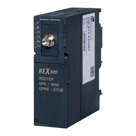
Mounting the device
Observe the ambient temperature. Ensure
sufficient cooling.
Snap the device onto a top-hat rail accord-
ing to DIN EN 60715. See image for instal-
lation position.
Connect the external power supply to the
connection terminal (3). Recommendation:
Use white-yellow connection terminal.
Connect KNX line with red-black bus termi-
nal (2).
Attach cover cap over the KNX/external
power supply connection.
Establish network connection by plugging
RJ45 plug into RJ pin jack (7).
Insert microSD card into the card reader (8)
(IP router).
Attaching the cover cap, Fig. 3
A cover cap must be attached to protect the
bus connection from dangerous voltages in
the connection area.
Guide bus line to the rear.
Attach cover cap over the bus terminal until
it engages.
Removing the cover cap, Fig. 4
Press cover cap on the sides and remove.
Start-up
Load the physical address and application
software
Start-up software from ETS 4.2.
IP router/IP interface
Briefly press the programming button (1) (<
4 seconds).
Programming LED (4) lights up red.
Assign physical address.
Programming LED (4) goes out.
Label device with physical address.
Load application software, filter tables,
parameters, etc.
IP-router as data logger/clock
Press the programming button (1) longer (>
4 seconds).
Programming LED (4) lights up yellow.
Assign physical address.
Programming LED (4) goes out.
Label device with physical address.
Load application software and parameters.
Technical data
KNX medium TP1
Start-up mode S mode
KNX rated voltage DC 21…30 V
SELV
KNX current consumption Typically 85 mA
KNX connection Bus connection
terminal
External supply
voltage DC 24...30 V
Power consumption 2 W (for DC 24 V)
Connection Connection ter-
minal
IP communication Ethernet 10/100
BaseT
(10/100 Mbit/s)
IP connection RJ45 pin jack
Supported protocols ARP, ICMP,
IGMPv3, DHCP,
AutoIP, UDP/IP
(Core, Routing,
Tunnelling,
Device Manage-
ment)
microSD card Max. 32 GByte
(SDHC)
Ambient temperature 0 °C to +45 °C
Storage temperature -25 °C to +70 °C
Installation width 36 mm (2 MW)
Warranty
The warranty is provided in accordance with
statutory requirements via the retailer.
Please submit or send faulty devices postage
paid and with an error description to your
sales representative (retailer/installation
company). They will forward the devices to
the Gira Service Center.
Use as Physical address
Line coupler x.y.0
Area coupler x.0.0
Data interface x.y.a
Data logger/
Clock
x.y.b
