Pro-face GLC300-TC41-24V User manual

WARNINGS
When Designing your GLC System:
- Be sure to design your GLC control system so that in the event of a main power
supply failure or a GLC accident, the user system’s overall safety integrity will be
maintained. If this is not done, incorrect output signals or a GLC malfunction may cause
an accident.
(1) Interlock circuits, etc. designed to interrupt or oppose normal machine movement
(i.e. Emergency Stop, General Protection, forward and reverse rotation, etc.), as well
as those designed to prevent machine damage (i.e. for upper, lower and traverse
movement limit positioning, etc.) should all be designed to be located outside of the
GLC.
(2) Whenever the GLC generates a “Watchdog Timer Error”, GLC operation will halt.
Also, when Errors occur in Input/Output control areas that the GLC cannot detect, it
is possible for unexpected movement to occur in those areas. As a result, for the
purpose of preventing unsafe machine movement, a “Failsafe Circuit” should be
created which is completely external to the GLC.
(3) If an problem arises with an external unit’s relay or transistor, causing an output
(coil) to remain either ON or OFF, a major accident can occur. To prevent this, be
sure to set up external watchdog circuits that will monitor vital output signals.
- Design a circuit that will supply power to the GLC’s I/O unit before starting up the
GLC. If the GLC’s internal program enters RUN mode prior to the I/O unit’s load
control power turning ON, an incorrect output (signal) or malfunction could cause an
accident to occur.
- Design a user program that will ensure the safety of the user’s system, in the event of a
GLC display or control error, or in the event of either a data transmission error or
power failure between the GLC and a connected unit. These types of problems can
lead to an incorrect output (signal) or malfunction, which could thereby cause an
accident to occur.
- Do NOT use GLC touch panel switches to perform life-related or important accident
prevention operations. These operations should be performed by separate hardware
switches to prevent operator injury and machine damage.
Wiring Warnings:
- To prevent electric shock or equipment damage, prior to installing or wiring the GLC,
confirm that the GLC’s power cord is unplugged from the power supply.
- After completing any GLC wiring work, be sure the terminal block’s protective plastic
cover is reattached. If this cover is not reattached, an electric shock could easily
occur.
- High voltage runs through the GLC. Except for changing the backlight, do NOT
attempt to open the GLC, since there is a possibility of an electric shock.
- Do not use power levels with the GLC that are outside of the GLC’s specified power
range. Doing so may cause a fire, electric shock or damage the GLC.
- Do not operate or store the GLC in areas where flammable gasses are present, since
operating the GLC may cause an explosion.
DANGERS

Operation and Maintenance Warnings:
- Never touch a live power terminal. This could cause a shock or machine malfunction.
- Due to the danger of an electric shock, confirm that the GLC’s power cord is un-
plugged before either cleaning the GLC or attaching/detaching the power terminal
screws.
- When replacing the GLC’s backlight, be sure to unplug the unit’s power cord to
prevent a shock, and wear gloves to prevent being burned.
- The GLC uses a lithium battery for backing up its internal clock and control memory
data. If the battery is incorrectly replaced (i.e. the + and - sides are reversed), the
battery may explode. Therefore, before changing the battery, Digital recommends that
you contact your local GLC distributor for battery replacement instructions.
- Do not attempt to modify the GLC’s internal parts or wiring in any way, since this may
lead to either a shock or fire.
CAUTIONS
Wiring Layout Cautions:
Be sure that all GLC input/output signal lines are isolated from all power wiring or
power cables, via a separate wiring duct. This is to prevent excessive noise, which can
cause a unit malfunction.
Installation Cautions:
- When attaching the I/O unit to the GLC, be sure that all the I/O unit’s attachment
screws are used and the unit is securely attached to the GLC. If the I/O unit is not
attached securely in place, the I/O unit may be damaged if it falls off the back of the
GLC, or a system-related malfunction or accident may occur due to I/O data signal
problems.
- Be sure any data cable attached to the GLC’s connector is securely attached. If the
cable and connector pins do not all make complete contact, incorrect input or output
signals can result.
General Wiring Cautions
- To prevent shocks or malfunctions, GLC’s FG (earth) wire should be grounded
according to the following:
1) A maximum grounding resistance of 100 W or less.
2) A grounding wire of 2mm2or larger should be used.
- The GLC’s wiring should be checked to confirm both that the operating voltage and
wiring terminal locations are correct. If either the voltage or the wiring terminal loca-
tions are incorrect, it can cause a fire or accident.
- Be sure to secure all wiring terminal screws in place with the designated torque. Screws
and terminals that become loose can cause a short circuit, fire or accident.
- Be sure that metal filings or wiring remnants do not fall inside the GLC, since they can
cause a fire, accident, or malfunction.
GLC Operation and Maintenance Cautions
- Be sure to read the GLC’s manual and on-line help information carefully before per-
forming program changes, forced output, or utilizing the RUN, STOP or PAUSE
commands while the GLC is in operation. Mistakes concerning the use of these items
can cause a machine accident or damage.
GLC Unit Disposal Cautions
- The GLC unit should be disposed of in a manner appropriate to the user country’s
industrial machinery disposal standards.

The GLC300-TC41-24V are UL / c-UL recognized products. (UL file No.E182139)
■GLC conforms as a component to the following standards:
・UL508
Industrial Control Equipment
・UL1604
Electrical Equipment for Use in ClassⅠand ⅡDivision 2 and Class Ⅲ
Hazardous (Classified) Locations
・CAN/CSA-C22.2, Nos.142, and 213-M1987
Standard for Safety of Information Technology Equipment, including
Electrical Business Equipment
GLC300-TC41-24V(UL Registration Model : 2780027-02)
・The GLC should be installed in the front face of a metal panel.
・If the GLC is installed so as to cool itself naturally, be sure to install it in a verti-
cal panel. Also, be sure that the GLC is mounted at least 100mm away from
adjacent structures and other equipment, otherwise, the heat generated by the
GLC's internal components may become higher than that allowed by UL stan-
dard requirements.
Installation and operation instructions are provided with each GLC. These installa-
tion instructions contain the following statements.
1. Power, input and output (I/O) wiring must all be in accordance with Class I, Division
2 wiring methods, Article 501-4 (b) of the National Electrical Code, NFPA 70, or as
specified in Section 18-152 of the Canadian Electrical Code for units installed within
Canada, and in accordance with that location's authority.
2. Suitable for use in Class I, Division2, GroupsA, B, C and D hazardous location, or
nonhazardous locations only.
3. WARNING: Explosion hazard-substitution of components may impair suitability for
Class I, Division2.
4. WARNING: Explosion hazard-do not disconnect equipment unless power has been
switched off or the area is known to be nonhazardous.
5. WARNING: Explosion hazard-when in hazardous locations, turn off power before
replacing or wiring modules.
UL / c-UL (CSA)Approval
CE Marking
GLC300-TC41-24V are CE marked , EMC compliant products.These units also
conform to EN50081-2 , EN50082-2 directives.
The following items are included in the GLC's package. Prior to using the GLC, be sure
to confirm that all the parts shown below are present.
This unit has been carefully packed, with special attention to quality. However,
should you find anything damaged or missing, please contact your local GLC dis-
tributorimmediately.
Package Contents
User's Manual
(Sold Separately)
GLC300 User’s Manual
GLC Option Items
Logic Program Development soft-
ware (Sold Separately)
Pro-Control Editor
GLC Unit
( GLC300-TC41-24V)
Operation Instructions (1 )
( this sheet )
Installation fasteners ( 4 pcs )
Operation
Instructions
Digital
(GLC300-MM01-ENG)
Digital
GLC300GLC300
GLC300GLC300
GLC300
User'sUser's
User'sUser's
User's
ManualManual
ManualManual
Manual
Pro-Control
Editor
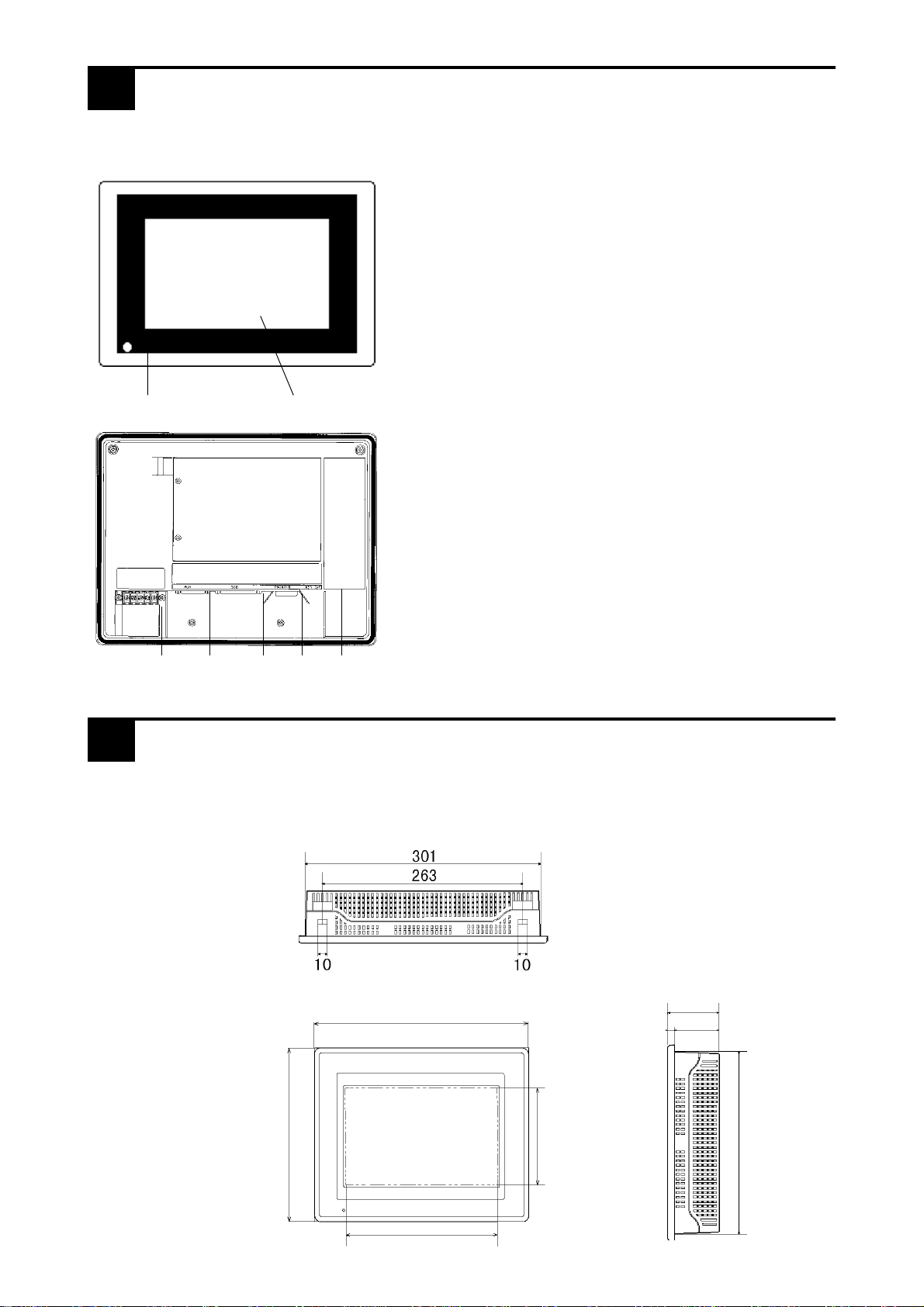
The GLC's part names and their functions are explained below.
1Names and Functions of GLC Parts
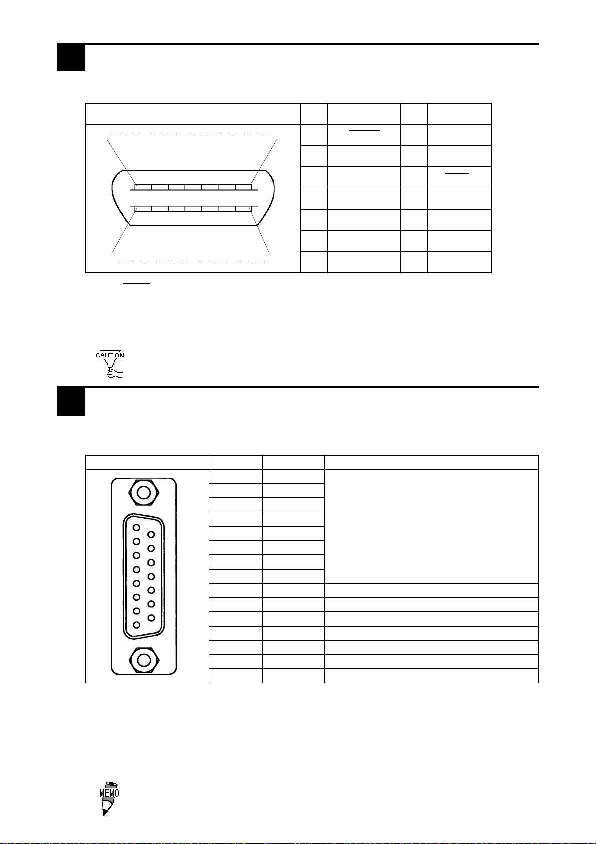
The GLC300-TC41-24V unit dimensions are as follows.
2Dimensions
A:Display
The monitor screen that indicates screens and data of
the host.
GLC300-TC41-24V : TFT-type color LCD
B:Touch Panel
Runs any screen change operations and sends data to
the PLC.
C:Power Lamp
Lights up when the power is turned On. (Normally
:Green LED)
D:Power Input Terminal Block
The input and ground terminals for AC power cable.
E:Auxiliary Input/Output (AUX)
Operates the Touch Switch, System Alarm, Buzzer,
Run outputs, and Remote Reset inputs.
F:Serial Interface
RS-232C, RS-422 (Serial) interface. Connect to the
Host.
G:Printer Interface
Connect the printer here.
H: Tool Connector
Connect the Downloading Cable, or a Bar Code
Reader here.
D FE GH
A,BC
unit:mm TopView
85
77.5
227
7.5
SideView
158.4
211.2
243
FrontView
317

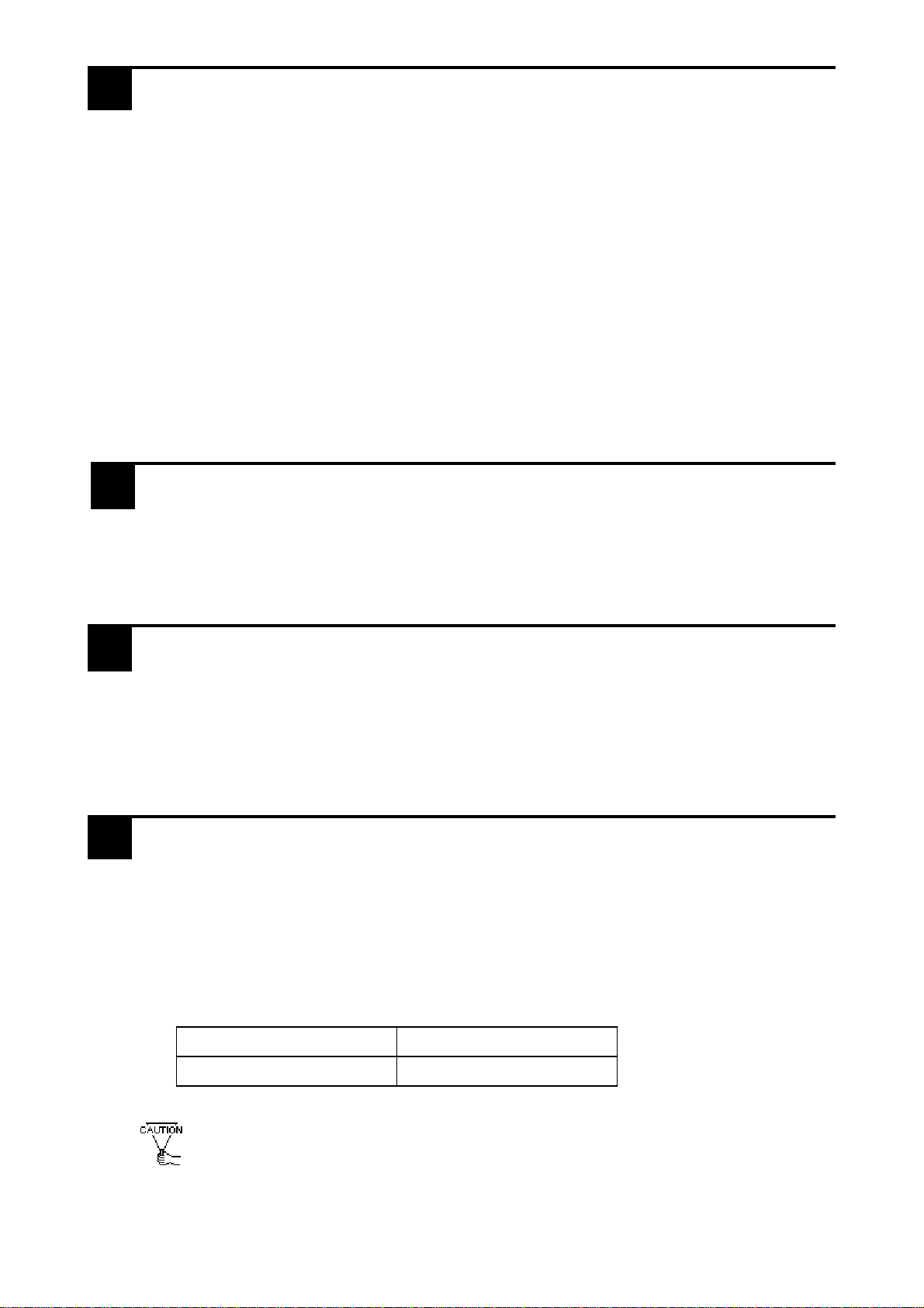
Pin
#Si
g
nal
Name Condition Pin
#Si
g
nal
Name Condition
1FGFrame
g
round 14 VCC 5V±5% output
0.25A
2SD
Send data
(
RS-232C
)
15 SDB Send data B
(
RS-422
)
3RD
Receive data
(
RS-232C
)
16 RDB Receive data B
(
RS-422
)
4RS
Request send
(
RS-232C
)
17 NC No connection
5CS
Clear send
(
RS-232C
)
18 CSB Clear send B
(
RS-422
)
6 NC No connection 19 ERB Enable receive B
(
RS-422
)
7GNDSi
g
nal
g
round 20 ER Enable receive
(
RS-232C
)
8CD
Carrier detect
(
RS-232C
)
21 CSA Clear send A
(
RS-422
)
9TRMX
Termination
(
RS-422
)
22 ERA Enable receive A
(
RS-422
)
10 RDA Receive data A
(
RS-422
)
23
RESERVED
Reserved for future
use
11 SDA Send data A
(
RS-422
)
24 NC No connection
12 NC No connection 25
RESERVED
Reserved for future
use
13 NC No connection
This serial port is used for the GLC's RS-232C and RS-422 interface cables.
3Serial Interface
RecommendedConnector: Dsub25pinplug XM2A-2501<madebyOMRONCorp.>
RecommendedCover : Dsub25pinCover XM2S-2511<madebyOMRONCorp.>
JackScrew XM2Z-0071<madebyOMRONCorp.>
•Use rough metric type M2.6 x 0.45p threads used to hold the cable’s set
(fastening) screws in place.
RecommendedCable : CO-MA-VV-SB5Px28AWG<madebyHITACHICableLtd.>
1
13
14
25
* Pin # 14 can be used for the power supply for the user's optional equipment connected
to the GLC.
*
• Pin # 14 is not protected, so be sure to use it only within its rated range.
• Be sure to connect the GLC's Pin # 7 (SG) terminal to the other (Host) unit's Signal
Groundterminal .
When making a cable, please be aware of the following:
<For RS-422 Connection>
•The following pairs of pin #’s must be connected to each other
...#18 (CSB) <-> #19 (ERB)
...#21 (CSA) <-> #22 (ERA)
•When connecting the RS-422 cable and the #9 (TRMX) and #10 (RDA)
points, a termination resistance of 100Ωis added between RDA and RDB.
•When the GLC is set as a Memory Link type and the cable type is RS-422, a
4-line system must be setup.
<For RS-232C connection>
•Do not connect #9 (TRMX), #10 (RDA), #11 (SDA), #15 (SDB), #16 (RDB),
#18 (CSB), #19 (ERB), #21 (CSA), and #22 (ERA).
This is the printer interface port in the rear side of GLC unit.
4Printer Interface
7
14
1
8
Pin Connection Pin# Signal Name Pin# Signal Name
1PSTB8PDB6
2PDB09PDB7
3 PDB1 10*1 INIT
4PDB211BUSY
5PDB312NC
6PDB413NC
7PDB514GND
*1 When INIT signal is not used, #10 pin's connection is not necessary.
RecommendedConnector: FCN-787P014-G/R <manufacturedbyFUJITSU,Inc.>
RecommendedCover: FCN-780C014-D/E <manufacturedbyFUJITSU,Inc.>
•Do not connect to pin #12 and #13.
An auxiliary interface for touch switch output, system alarm output, RUN output, and
remote reset input.
*1 The AUX Alarm outputs in the following two cases:
•HardwareAlarm(SCREENMEMORYCHECKSUMERROR)
•Software Alarm (SYSTEM ERROR, i.e. incorrect data that makes continuation
of screen operation impossible or when Watchdag Timer's Alarm output occurs11)
RecommendedConnector: Dsub 15 pin Plug XM2A-1501 <madebyOMRONCorp.>
RecommendedCover: Dsub15pinCover XM2S-1511 <madebyOMRONCorp.>
JackScrew XM2Z-0071 <madebyOMRONCorp.>
•Use rough metric type M2.6 x 0.45p threads used to hold the cable’s set
(fastening) screws in place.
5AUX Interface (Input/Output)
1
8
9
15
Pin Connection Pin# Signal name Contents
1TSW0 Touch Switch OutPut
2TSW1
3TSW2
4TSW3
5TSW4
6TSW5
7TSW6
8TSW7
9RUN Out
p
ut:On in RUN mode;Off in standb
y
mode
10 ALARM Alarm Out
p
ut
;
When On
,
GP unit alarmori
g
in*1
11 BUZZ Buzzer Output
12 DC24V Output-Common(DC24V)
13 AIN-C Input-Common(DC24V)
14 AOUT-C Output-Common(GND)
15 RESET Reset Input

■Cut a hole in the panel, and install the GLC into the panel's front face.
■Attach the Installation Fasteners from the inside of the panel.
Tighten all installation fasteners with a screwdriver.
To create a waterproof seal, a force of 0.5-0.6N•m is required.
Panel GLCunit
•Tightening the screws with too much force can damage the GLC.
•Before installing the GLC, be sure that the moisture resistant
gasket is attached securely to the unit.
6Installation
Rear of GLC
Gasket
1.6mmto10mm
Panelthickness
302
under 4-R2
228
Unit:mm
-0
+1
-0
+1

•To avoid the possibility of an electric shock, be sure the Power Cord is unplugged
from the power outlet prior to connecting the power cord's power terminals to the
GLC.
•The GLC300-TC41-24V can only use DC24V input. Any other input voltage can
damage the GLC and its power supply.
•Since the GLC has no power switch, be sure to use a breaker type switch.
•To prevent a short from occurring when the ring terminals
become loose, be sure to use sleeved ring terminals.
•When the FG terminal is connected, be sure the wire is
grounded. Not grounding the GLC unit will result in excess
noise and vibration.
• Wherever possible, use thick wires (max. 2 mm2) for power
terminals, and twist the wire ends before attaching the ring terminals.
•Be sure to use the following size Ring Terminals.
7Wiring
Under
6.0mm
Over φ 3.2 mm
WARNING
*1Ring Terminal to use: V2-MS3 (made by JST)
Rear side
-
+FG + - FG Ring Terminals *1
Power Input
Terminal Block
Connect the power cable following the steps below.
1. Check to make sure the Power is Off.
2. With a plus screwdriver, remove the cover on the Power Input Terminal Block.
3. Disconnect the screws from the 3 terminals to be used, align the wire rings and
re-insert the screws.
(Please make sure the connection of the wires are correct.)
•The torque necessary for fastening the screws is between 0.5-0.6N•m.
•From the FG terminal at the rear side of GLC unit, please take grounding exclusively
[within ground resistance of 100 Ω].
9Precaution for Grounding
Please pay special attention to the following instructions when connecting the power
cable to the GLC unit.
•If the supply voltage exceeds the GLC unit range, connect a voltage transformer.
•For between the line and ground, select a power supply that is low in noise. If there is an
excess amount of noise, connect a noise reducing transformer.
•When supplying power to the GLC unit, please separate the input/output and operation
unit lines.
•To increase the noise quality, simply twist the power cable before connecting it to the
GLC unit.
•The power supply cable must not be bundled or kept close to main circuit lines (high
voltage, high current), or input/output signal lines.
•Connect a surge absorber to deal with power surges.
•To reduce noise, make the power cable as short as possible.
8Precautions for Supplying Power
11 Replacing the Backlight
10 Precautions for Input/Output Signal Lines
•Input and Output signal lines must be separated from the power control cables for op-
erational circuits.
•if this is not possible, use a shielded cable and the shield should be grounded.
•The backlight on this unit can be replaced.
For an explanation of how to replace it, please refer to the GLC300 Series User’s
Manual (sold separately) or the instruction manual which comes with replacement
backlights (sold separately).
Applicable backlight models
•Using any backlight other than the applicable models shown above may cause
an accident or breakdown.
GP unit Backlight model
GLC300-TC41-24V GP577RT-BL00-MS
•If this is not possible, use a shielded, grounded cable.
Table of contents
Popular Control System manuals by other brands

VALCOBABY
VALCOBABY MCP-25/MS manual

Firestone
Firestone 2554 installation instructions

Signature Control Systems
Signature Control Systems EZ Indoor 8124US Installation and programming guide

HIK VISION
HIK VISION DS-K260X-G Quick setup guide

Astral Pool
Astral Pool LumiPlus 75813 Installation and maintenance manual

BM PRO
BM PRO RVMaster Help guide


