Woodway Engineering Ltd
Lower Road, Barnacle
Coventry, CV7 9LD
United Kingdom
Tel: +44 (0) 24 76 841750
Fax: +44 (0) 24 76 621796
www.woodwayengineering.com INSTALLATION GUIDE
6
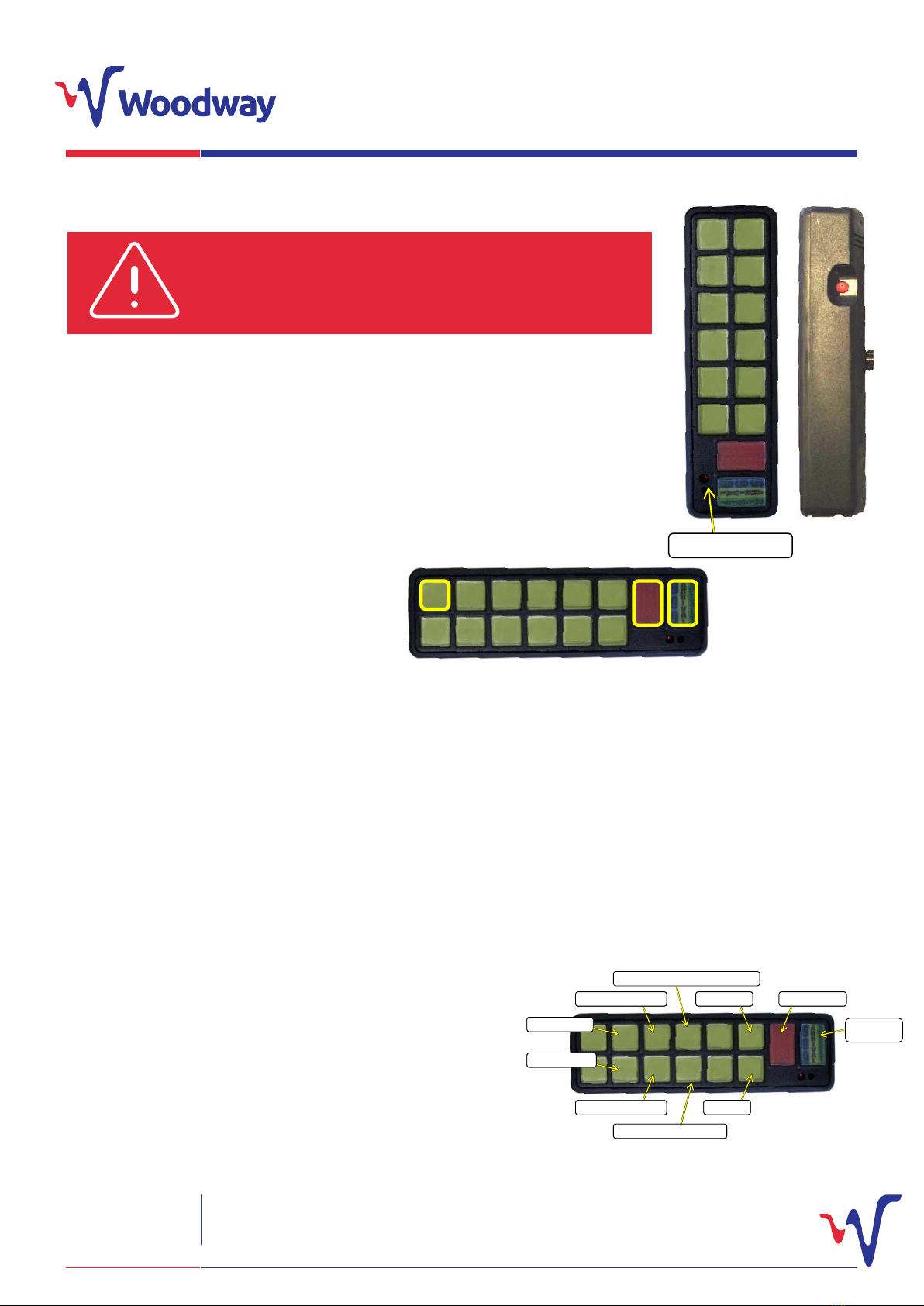
Keypad Programming
To adjust the volume of the internal microphone, enter
programming mode (see above). Press and hold the channel 3 key
until the unit beeps. This unit will now be in volume adjustment
mode. While this mode is active the channel 3 switch will ash.
Channel 11 (volume up) and channel 12 (volume down) adjust the
microphone volume. Volume adjustment takes around 8 seconds
to go from minimum to maximum. When you have nished press
the 999/arrival/reset key to save the settings. You may now program
another option or perform the programming key press to return to
normal operation.
When in programming mode, button 8 can be held to toggle this
function. The LED will either light, to show this mode is active or go
out, showing that it is disabled. You will also here a low level bleep
when toggling modes. This is programmed the same way as the
external 999 switch. When enabled, if the unit is in pursuit mode
(999 mode) and +12V is applied to the red/blue 999 wire, the unit
will move automatically to arrival mode. If the mode is required on
a 0V switched hand brake, a relay will need to be used. Press the
999/ARRIVAL/RESET button to turn all switches o and again to go
into 999 mode. You may now program another option or perform
the programming key press to return to normal operation. The
external 999 and Highways Agency modes do not operate
together, ensure only one mode is activated at one time.
If a group of keys are required to self cancel if one or other in that
group is pressed, rst enter programming mode (detailed above).
Now depress and hold the channel 5 selection key, the warning
LED will ash and the keys that are required in the groups can be
pressed. The keys in the group will stay lit when selected. When all
the keys that are required in the group are lit up, press the 999/
arrival/reset button to save the set up and clear the selections. You
may now program another option or perform the programming key
press to return to normal operation. Two separate groups of self
cancelling groups can be dened.
To program self cancelling group 2, enter programming mode, press
and hold the channel 6 selection key and repeat the operation
above.
If more than one self cancelling group channel is incorporated as
part of a 999 or arrival selection, all channels will become active
at the same time. It is therefore advised that any self cancelling
groups should be dened before the 999 or arrival modes are
programmed.
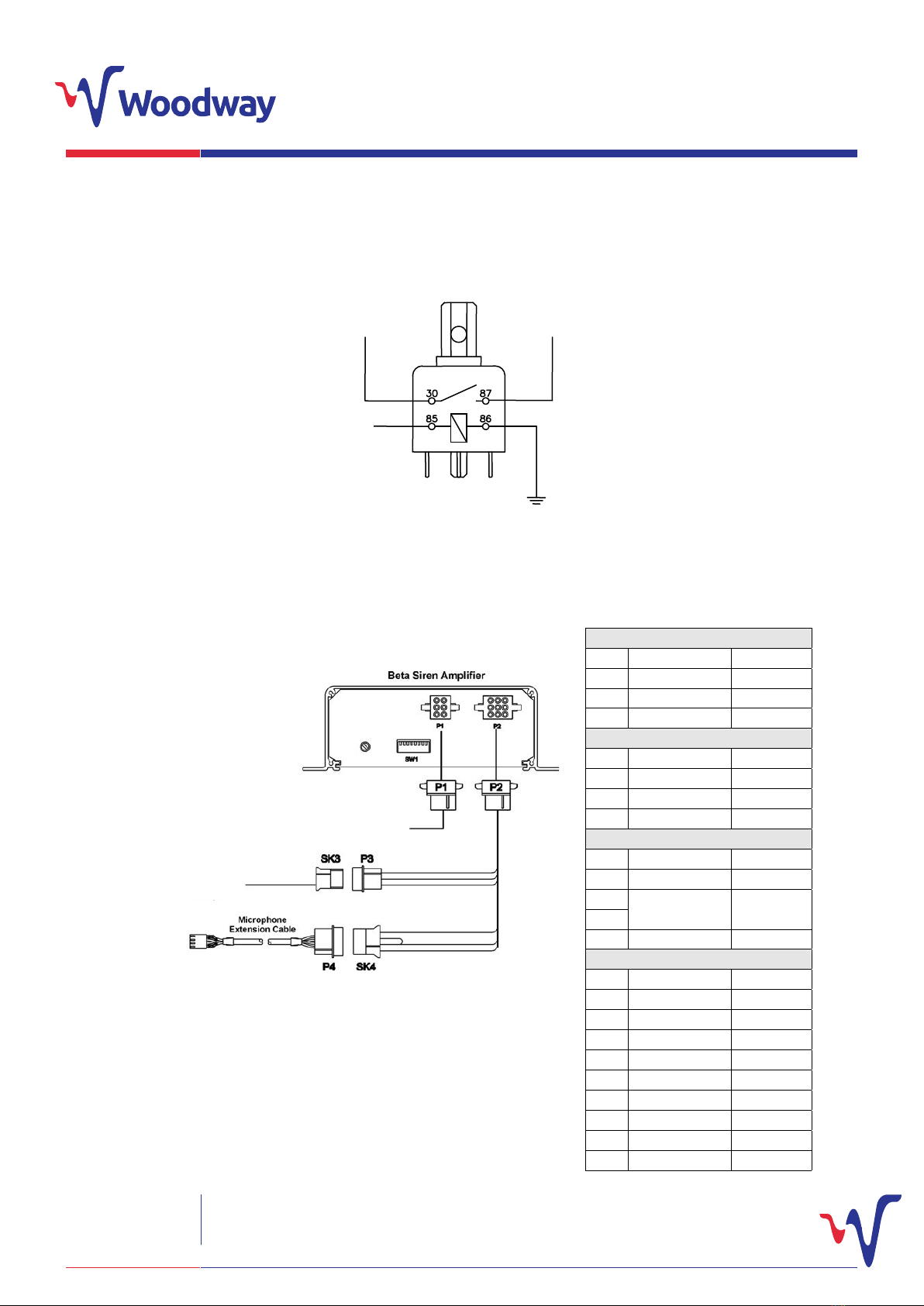
When in programming mode, button 7 can be held to toggle
this function. The LED will either light, to show this mode is
active or go out, showing that it is disabled. You will also here
a low level bleep when toggling modes. To use the external
999 function, connect the RED/BLUE wire on the output/
receiver module to a momentary switch that is connected to
+12V. Hold the switch for more than half a second to activate
the 999 mode. Cancel the 999 mode in the usual method,
press the 999/ARRIVAL/RESET button to go to arrival mode
and press it again to reset the switch panel. You may now
program another option or perform the programming key
press to return to normal operation. The external 999 and
Highways Agency modes do not operate together,
ensure only one mode is activated at one time.
Channel keys 1 - 12 can be turned into momentary action
keys. When set-up, a channel will only be active whilst the key
is pressed. This is useful for creating a button to drive an air
horn for example. If this channel happens to be part of the
999 pursuit or arrival selection when activated the channel
will come on for a short period and automatically cancel
itself.
To program which keys are momentary enter programming
mode then hold the button for channel 4 for over 2 seconds
until a low level beep is heard and the light goes out. Then
select which channels are momentary by turning that
channel on. Finally press the 999/arrival/reset key to store
the selection. You may now program another option or
perform the programming key press to return to normal
operation.
The system can be restored to the factory default set-up by
pressing and holding the siren key whilst in programming
mode. The factory default set-up is currently dened as
follows:
999 Pursuit: 360degree Strobes (front and rear); Channel 3;
4 and Siren On.
Arrival: 360degree Strobes; Channel 4 On; Siren O.
No momentary keys and self-cancelling groups.
Microphone Volume set at 50%.
External 999 and Highways modes are disabled.
Public Address Microphone Volume
Highways Agency Mode
Self Cancelling Switches
External 999 Activation
Momentary Key Selection
Factory Default Set Up