manuals.online logo
Brands
  1. Home
  2. •
  3. Brands
  4. •
  5. Pro-Form
  6. •
  7. Treadmill
  8. •
  9. Pro-Form SEARS 730si User manual

Pro-Form SEARS 730si User manual

Other manuals for SEARS 730si

3

This manual suits for next models

1

Other Pro-Form Treadmill manuals

Pro-Form DTL52950 User manual

Pro-Form

Pro-Form DTL52950 User manual

Pro-Form 785 TL User manual

Pro-Form

Pro-Form 785 TL User manual

Pro-Form 660 Vx Treadmill Quick start guide

Pro-Form

Pro-Form 660 Vx Treadmill Quick start guide

Pro-Form 575 Crosstrainer Treadmill Operating and maintenance manual

Pro-Form

Pro-Form 575 Crosstrainer Treadmill Operating and maintenance manual

Pro-Form 6.5 X Treadmill Setup guide

Pro-Form

Pro-Form 6.5 X Treadmill Setup guide

Pro-Form 831.299560 User manual

Pro-Form

Pro-Form 831.299560 User manual

Pro-Form 435ex Treadmill User manual

Pro-Form

Pro-Form 435ex Treadmill User manual

Pro-Form 850 T Treadmill User manual

Pro-Form

Pro-Form 850 T Treadmill User manual

Pro-Form 831.297000 User manual

Pro-Form

Pro-Form 831.297000 User manual

Pro-Form Crosswalk 400e User manual

Pro-Form

Pro-Form Crosswalk 400e User manual

Pro-Form 520 PETL52010 User manual

Pro-Form

Pro-Form 520 PETL52010 User manual

Pro-Form PFTL71330 User manual

Pro-Form

Pro-Form PFTL71330 User manual

Pro-Form 730 Zlt Treadmill User manual

Pro-Form

Pro-Form 730 Zlt Treadmill User manual

Pro-Form PT6.0 PFTL69501 User manual

Pro-Form

Pro-Form PT6.0 PFTL69501 User manual

Pro-Form 485 Crosswalk Cwl Treadmill Quick start guide

Pro-Form

Pro-Form 485 Crosswalk Cwl Treadmill Quick start guide

Pro-Form 831.297001 User manual

Pro-Form

Pro-Form 831.297001 User manual

Pro-Form TREADMILL 831.299572 User manual

Pro-Form

Pro-Form TREADMILL 831.299572 User manual

Pro-Form 745cs User manual

Pro-Form

Pro-Form 745cs User manual

Pro-Form 630 User manual

Pro-Form

Pro-Form 630 User manual

Pro-Form PFTL57706.0 User manual

Pro-Form

Pro-Form PFTL57706.0 User manual

Pro-Form 1195 ZLT User manual

Pro-Form

Pro-Form 1195 ZLT User manual

Pro-Form 70 Treadmill User manual

Pro-Form

Pro-Form 70 Treadmill User manual

Pro-Form 480 Cx Treadmill Operating and maintenance manual

Pro-Form

Pro-Form 480 Cx Treadmill Operating and maintenance manual

Pro-Form 785 TL User manual

Pro-Form

Pro-Form 785 TL User manual

Popular Treadmill manuals by other brands

Motus M990T Service manual

Motus

Motus M990T Service manual

NordicTrack APEX4100i NTTL18906 user manual

NordicTrack

NordicTrack APEX4100i NTTL18906 user manual

CAPITAL SPORTS Pacemaker Touch manual

CAPITAL SPORTS

CAPITAL SPORTS Pacemaker Touch manual

Insportline Hill Pro user manual

Insportline

Insportline Hill Pro user manual

Expondo Gymrex GR-MG31 user manual

Expondo

Expondo Gymrex GR-MG31 user manual

HEALTH ONE Walk Ro user manual

HEALTH ONE

HEALTH ONE Walk Ro user manual

NordicTrack T7.5 S user manual

NordicTrack

NordicTrack T7.5 S user manual

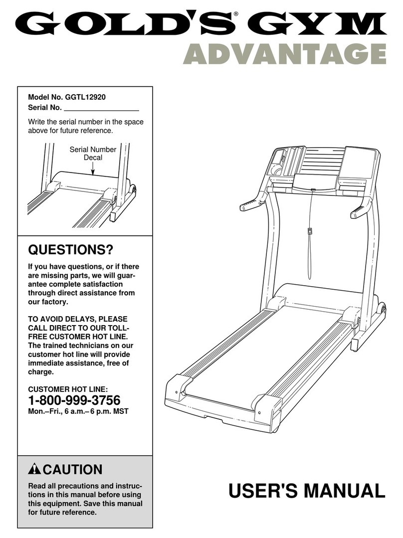
Gold's Gym ADVANTAGE GGTL12920 user manual

Gold's Gym

Gold's Gym ADVANTAGE GGTL12920 user manual

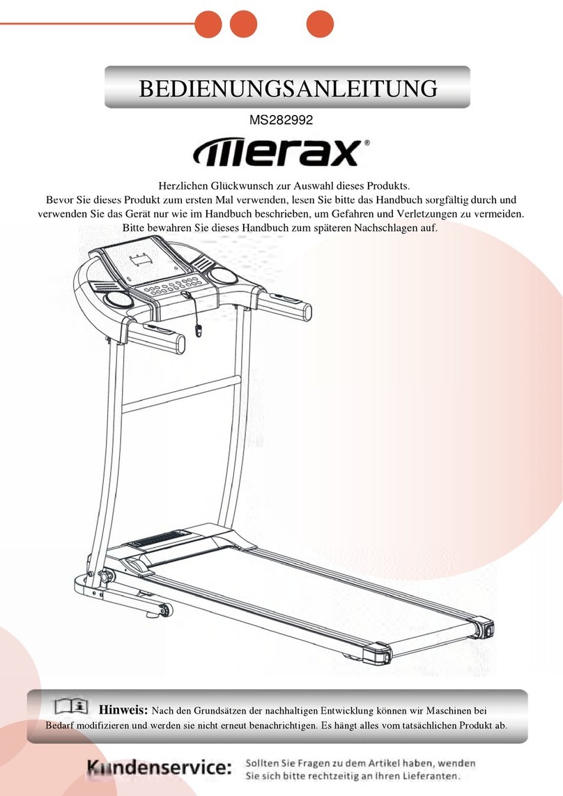
Merax MS282992 manual

Merax

Merax MS282992 manual

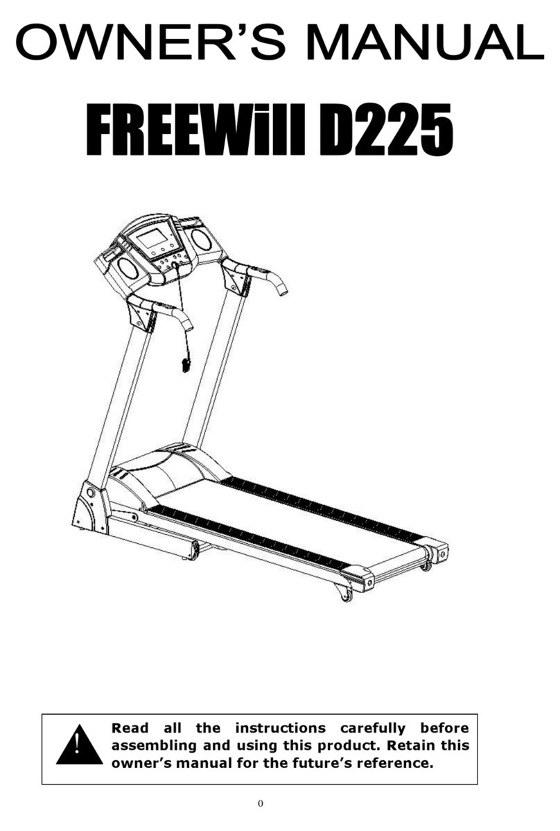
FitLogic freewill d225 owner's manual

FitLogic

FitLogic freewill d225 owner's manual

HOP-SPORT ESTIMA HS-3200LB instruction manual

HOP-SPORT

HOP-SPORT ESTIMA HS-3200LB instruction manual

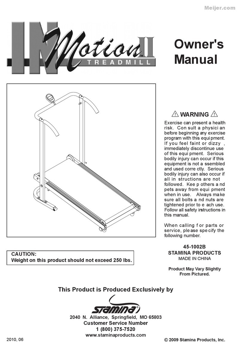
Stamia InMotion II owner's manual

Stamia

Stamia InMotion II owner's manual

Smooth Fitness EVO 3i user manual

Smooth Fitness

Smooth Fitness EVO 3i user manual

NordicTrack NETL81810.0 user manual

NordicTrack

NordicTrack NETL81810.0 user manual

Schwinn 830/Journey 8.0 Assembly manual / owner's manual

Schwinn

Schwinn 830/Journey 8.0 Assembly manual / owner's manual

Keys Fitness HealthTrainer HT-740T owner's manual

Keys Fitness

Keys Fitness HealthTrainer HT-740T owner's manual

Spirit XT8 Service manual

Spirit

Spirit XT8 Service manual

NordicTrack T 14.0 Treadmill Manuel de l'utilisateur

NordicTrack

NordicTrack T 14.0 Treadmill Manuel de l'utilisateur

manuals.online logo
manuals.online logoBrands
  • About & Mission
  • Contact us
  • Privacy Policy
  • Terms and Conditions

Copyright 2025 Manuals.Online. All Rights Reserved.

SEARS
Model No. 831.297741
Serial No.
The serial number can be found in the
locationshown below. Write the serial
number in the space above.
E_X z=" R C I S _"
EQ u i F, I,,.4 i=- I,,4T
11Oil I_1 i Iol _11-I
HELPLINE!
1-800-736-6879
USER'S MANUAL
SEARS, ROEBUCK AND CO., HOFFMAN ESTATES, IL 60179
PRO;FORM
TABLE OF CONTENTS
•IMPORTANT PRECAUTIONS ....................................
•BEFORE YOU BEGIN ..........................................
"ASSEMBLY ..................................................
HOW TO USE THE PULSE SENSOR ..............................
OPERATION AND ADJUSTMENT ................................
" HOW TO USE THE MANUAL MODE ............................
HOW TO USE PROGRAMS A, B, C, AND D ......................
HOW TO USE THE FAT BURN AND AEROBIC PROGRAMS ........
HOW TO USE THE FITNESS I'EST PROGRAM ...................
HOW TO FOLD AND MOVE THE TREADMILL ......................
TROUBLE-SHOOTING .........................................
CONDITIONING GUIDELINES ....................................
°*oo.°.oo.°.o.o..o.*
°°.oo.°..o°.°°......
°°°°*.°oo..o°.°oo°.o
.°°°°o°°.oo.°oo°.°o,
o°oo..°.oo°.oo,°°oo*
°°ooo°°°o°°°o°°°ooo°
°.°o*°*,°°°°.°,.,..,,°°°o°.,3
.°o°,°°_°°.°°°°.,*o°.o°..°°°.4
°°°°°,o°°*oo°.°.o°°.o°o°o°..5
°°°.o°,°.° .... °..,,o.°.o°...8
°,°°°°°,°,°°°o°°..°°°°°°°,°°9
...... 11
...... 13
...... 15
...... 16
...... 18
...... 20
.......................,..22
ORDERING REPLACEMENT PARTS .................................................. Back Cover
FULL 90 DAY WARRANTY ........................................................... Back Cover
Note: An EXPLODED DRAWING and a PART LIST are attached to the center of this manual. Save the
EXPLODED DRAWING and PART LIST for future reference.
2"
IMPORTANT PRECAUTIONS
BEFORE YOU BEGIN
Thank you for selectingthe PROFORM" 730si tread-
mill.The 730si treadmill blendsadvanced technology
with innovativestylingto provideyou with an excellent
form of cardiovascular exercise in the convenience and
privacyof your home. The 730si offers an impressive
array offeatures designedto make your workouts more
enjoyable and effective. Andwhen you're not exercis-
ing, the unique 730sl can be folded up, requiring less
than half the floor space ofother treadmills.
For your benefit, read this manual carefully before
using the treadmill. Ifyou have additional questions,
please call ourtoll-free HELPLINE at 1-800-736-6879,
Monday through Saturday, 7 a.m. until 7 p.m. Central
13me(excluding holidays). To help us assistyou,
please note the product model number and serial num-
ber before calling. The model number of the treadmill
is831.297741. The serial number can be found on a
decal attached to the treadmill (see the frontcover of
this manual for the location).
Before reading further, please review the drawing
below and familiarize yourself with the pads that are
labeled.
Water Bottle*
Holder
Tray
*Water Bottle isnot included
Storage Latch, Console
Key/Clip
Handrails,
Walking Belt,
Foot Rails
Circuit Breaker
On/Off
FRONT
BACK
Rear Roller
Adjustment Bolt
Cushioned Walking
Platform for maximum
exercise comfod
RIGHT SIDE
4"
ASSEMBLY
Assembly requires two people. Set the treadmill in a cleared area and remove all packing materials. Do not dis-
pose of the packing materials until assembly iscompleted. Tools required for assembly: The included allen
wrench _andyour phillips screwdriver _and two adjustable wrenches _.
1. Attach six Base Pads (95) to the bottomof the Base (73)
in the indicated locations (see the insetdrawing). Note:
One additional Base Pad will be used in assembly step 6,
and one extra Base Pad is included.
2. Firmly hold the Uprights (6, 88) as shown. Raise the
Uprights until the base and the front Wheels (66) are
resting on the floor.
3. Loosen the Crossbar Bolts (t) in the ends of the Console
Crossbar (9). Pivot the Console (10) to the angle shown.
Look under the Left and Right Crossbar Brackets (3, 36)
and find the two small holes in each end of the Console
Crossbar (9). Tighten Crossbar Screws (84) intoall four
holes.
Rotate the Console (10) upward until itstops. Using the
7/32" end of the Allen Wrench (83), tighten the Crossbar
Bolts (1) in the ends of the Console Crossbar (9).
4. Next, the treadmill should be raised to the storage posi-
tion. Hold the treadmill with your hands in the locations
shown at the righL To decrease the possibility of In-
jury, bend your legs and keep your back stralght. As
you raise the treadmill, make sure to lift with your
legs rather than your back. Raise the treadmill about
halfway to the vertical position..
::::_>95
2 6
10
4
5
6"
5. Move yourdght hand to the position shownat the right,
and hold the treadmiti firmly. Using your left hand, rift the
storage latch. Raise the treadmill untilthe lockingpin
• snaps intothe storage latch. Make sure that the locking
pln Is Inslde the storage latch, and that the storage
latch Is fully closed.
.See the upper Inset drawing. Attach a Base Pad (95) to
the bottomof the Stabilizer Plate (81) in the indicated lo-
cation.
Stand behind the lreadmilL Hold the RightCrossbar
Bracket (36) and the LeftCrossbar Bracket (not shown).
Place one foot on the base in the indicatedlocation.
Tip the treadmill back slightly.While the treadmill is held
in this position,asecond person should slidethe
Stabilizer Plate (81) onto the base (see the lower inset
drawing). Keeping your foot on the base, carefully tip the
treadmillup until it is restingon the base. Make sure that
the Stabilizer Plate (81) stays on the base.
Attach the Stabilizer Plate (81) to the base with a
Stabilizer Plate Bolt (91), two Stabilizer Plate Washers
(94), and the Stabilizer Plate Nut (89) as shown.
7. Refer to assembly drawing 5 at the top of this page. Hold
the upper end of the treadmillwith your right hand as
shown. Using your left hand, liftthe storage latch. Pivot
the treadmill slightlyuntilthe locking pin isout ofthe stor-
age latch.
Hold the treadmill firmlywith both hands, and iower the
treadmill to the floor. To decrease the possibility of In-
Jury, bend your legs and keep your back stralght.
8. Remove the paper backing from the Wrench Clip (28).
Press the Wrench Clip ontothe Frame (49) in the indi-
cated location. Press the Allen Wrench (83) intothe
Wrench Clip.
Storage Latc_
6
36
7
8
89 If
26_
9. AttachthePulsesensor(105)toonectthe Headbands
(106 or 107). Make sure that the sensor window is
pressed through the indicated hole in the Headband.
Press open the clothes clip, and insed the pulse sensor
wire into the clothes clip. Make sure that the pulse
sensor wire Is resting agalnst the hinge of the
clothes clip (see the Inset drawing), The use of the
pulse sensor is explained on page 8.
_" " - Clothes
9 Sensor 105
Window
107
Pulse Sensor Wire
Make sure that all pads are tightened before you use the treadmill. Note: Place a mat beneath the treadmill to
protect the floor or carpet.
7
'HOLYTO'USE THE PULSE'SENSOR
8"
The uniqueheadband-stTle pulse sensorIs specta ly
designedfor greater accuracy, comfod, and durability.
To get the best performance from the pulse sen-
sor, please read the f611owing Instructions.
HOW TO ADJUST THE HEADBAND
Forthe pulse sensor to function properly,the head-
band shouldfitsnugly around your head, without being
uncomfortable.
To a_ust the
headband, in-
sed thead-
justmenttab
throughone
ofthe holes
in the head-
band. Note:
Each time
you exer-
cise, the headband may expand slightly during the
first few minutes of use. It may be necessary to
readjust the headband periodically.
HOW TO PUT ON THE PULSE SENSOR
Rub yourforehead bdefly to stimulate circulation.Put
on the headband as shown below, with the sensor win-
dow centered on your forehead. Make sure thatthere
is no hair between the sensor window and your fore°
head. Attach the clothes clipto yourcollar. The clothes
clipwillreduce the movement of the pulse sensor wire,
helping to ensure accurate pulse readings.
Sensor
Window
Clothes
L/
IMPORTANT: To avoid static build-up that may
damage the console, wear the pulse sensor only
while you are on the treadmill.
GUIDELINES FOR ACCURATE PULSE READINGS
The instructionson page 12 explain how the pulse
sensor isused with the console (see PULSE
DISPLAY). For the best results, remember the follow-
ingimpodant guidelines:
1. Before puttingon the headband, rub yourforehead
brieflyto stimulate circulation.
2. Make sure that the headband t'dssnugly, without
being uncomfortable. If the headband is too loose or
tight, yourpulse may not be detected.
.The headband must be wornwith the sensor win-
dow centered on your forehead. Make sure that
there is no hair between the sensor window and
yourfo_'ehead.Make-up appliedto the forehead
may interfere with pulse readings. Note: If the pulse
sensor does not detect your pulsewhen the sensor
window is centered on your forehead, try positioning
the sensor window above your dghtor left eyebrow.
Dependingon the shape ofyourforehead, it may be
easier to detect your pulsefrom a different position.
4. Make sure that the pulse sensor wire is fully
plugged intothe jack on the console.
5. Because yourpulse constantlychanges, the pulse
sensorwillsample your pulse everyfew seconds.
When you first put on the pulsesensor, itmay take
up to ten seconds for an accurate pulseto be shown.
6. Avoid excessive head movement during exercise.
7. The sensorwindow shouldbe cleaned weekly when
the treadmillis used regularly.Moisten acottonswab
withwater, and carefully wipe the sensorwindow.
HOW TO SOLVE COMMON PULSE PROBLEMS
1. Ifyou are weadng the pulse sensor and the NO
PULSE DETECTED indicatorlights,refer to guide-
I_nes2, 3, 4, 5, 6, and 7 above.
.
3.
If the pulseshown in the PULSE display seems ex-
cessivelyhigh or low, refer to guideline 5.
If error code "E5" appears in the PULSIE display,
refer to guidelines 2, 3, 4, 5, 6, and 7.
4. If the letters =PLS" appear In the PULSE display,
refer to guidelines 2, 3, 4, 5, 6, and 7.
CLEANING THE PULSE SENSOR AND HEADBAND
Remove the headband from the pulse sensor. Wipe
the pulse sensorwith a damp cloth; never Immerse
the pulse sensor In water. Hand wash the headband
in milddetergent, gently wdng it out, and let itair dry.
•OPERATION AND ADJUSTMENT ....."
THE PERFORMANT LUBE TM WALKING BELT
Your treadmill features a walking belt coated with
PERFORMANT LUBE _', a high-performance lubricant.
IMPORTANT: Never apply silicone spray or other
substances to the walking belt or the walking plat-
form. They will deteriorate the walking belt and
cause excessive wear.
HOW TO PLUG IN THE POWER CORD
DANGER:improper connection
of the equipment-grounding conductor can
result In an increased risk of electric shock.
check wit h a qualified electrician or service-
iman If you are indoubt as :towhether the
product Is properly grounded. Do not modify
the plug provided with the Product--if it will
not fit the outlet, have a proper outlet in-
stalled by a qualified electrician,
Your treadmill, like any other type of sophisticated
electronic equipment, can be seriouslydamaged by
sudden voltage changes in your home's power.
Voltage surges, spikes, and noise interference can re-
sult from weather conditions or from other appliances
being turned on or off.
To decrease the pos-
V . Q
_lblhty of your tread 1
mill being damaged,
always use a surge
protector (not In-
cluded) with your
treadmill.
Surge protectors are
sold at most hardware
stores and department
stores. Use only a UL-
listed surge protector,
rated at 15 amps, with a
14-gauge cord of five
feet or less In length.
This product must be
grounded. If it should
malfunction or break
down, grounding pro-
vides apath of least re*
sistance for electric cur-
rent to reduce the risk of
electric shock. This product is equipped with a cord
having an equipment-grounding conductor and a
grounding plug. Plug the power cord into a surge
protector, and plug the surge protector into an ap-
propriate outlet that ls properly installed and
grounded in accordance with all local codes and
•ordinances.
This product is for use on a nominal 120-volt circuit,
and has a grounding plug that looks like the plug illus-
trated In drawing 1 below. A temporary adapter that
lookslike the adapter illustrated in drawing 2 may be
used to connect the surge protector to a 2-pole recep-
tacle as shown in drawing 2 ifa properly grounded out-
letis not available.
The temporary adapter should be used only until a
properly grounded outlet (drawing 1) can be installed
by a qualified electrician.
The green-colored rigid ear, lug, or the like extending
from the adapter must be connected to a permanent
ground such as a properly grounded outlet box cover.
Whenever the adapter is used itmust be held in place
by a metal screw. Some 2-pole receptacle outlet box
covers are not grounded. Contact a qualified elec-
trlclan to determine If the outlet box cover Is
grounded before using an adapter.
/Grounded Outlet Box ff
/Treadmill Power Cord-. ///
..r_ /Grounding Pin (
I!._ "_",>._Grcunding Plug Grounding Plug,. j
=rounded Outlet L_ _<o -"_ _, _)
Ground,noP,ug Surge Protector
DIAGRAMOFTHECONSOLE
!'-
_2481_=Niumn__
c,:: ,_--'57 "159
"(z_"*'___.h----',r _o,,,,., _-=
.-
owlU_m _E/A_C_ff
-. 3.5J
Tp Note: Ifthere is a thin sheet ofclear plaso
ulse SensorJack tic on the face of the console, remove it.
10
FEATURES OF THE CONSOLE
The treadmillconsole offers an impressive array offee-
turesdesigned to make your workouts more effective
and enjoyable. When the console is in the manual mode,
thespeed and incline ofthe treadmill canbe changed
with a touchof a button. As you exercise, fivedisplays
will providecontinuous exercise feedback. Seven preset
programsare also offered. Programs A, B, C, and D au-
tomatically controlthe speed of the treadmillas they
guide you through effective workouts; the special FAT
BURN program provides intensive fat-burning workouts;
the AEROBIC program helpsyou to achieve maximum
cardiovascular benefits;and the unique FITNESS TEST
programmeasures your relative fitness level.
To use the manual mode, follow the steps on pages 11
through13. To use program A, B, C or D, see pages 13
and 14. To use the FAT BURN or AEROBIC program,
see pages 15 and 16. To use the FITNESS TEST pro-
gram, see pages 16 and 17. Note: The console can dis-
play speed and distance in either milesor kilometers
(see SPEED DISPLAY on page 12). Forsimplicity,all in-
stroctionsrefer to miles.
Beforebeginning,make sure
thattheon/off switch located
nearthe powercord is in the
"on" position.Plugin the power
cord(see page 9). Note: Ifthe
keyis in the console when the
Position
powercord isplugged in,the letters "PO" will flash in the
SPEED display.If this occurs, remove the key.