PRO Light Equinox MaxiPar Plus User manual

Equinox
MaxiPar Plus
User Manual
Order code:EQLED110
TABLE OF CONTENTS
1. Safety Instructions
2. Technical Specifications
3. How to set the Unit
4. DMX 512 Address setting
5. How to control the Unit
6. Troubleshooting
7. Fixture Cleaning
1. Safety Instructions
WARNING
Please keep this User Guide for future consultation. If you sell the unit to
another user be sure that they also receive this.
Unpack and check carefully that there is no transportation damage before
using the unit.
!Before operating, ensure that the voltage and frequency of the power supply
match the power requirements of the unit.
!It’s important to ground the yellow/green conductor to earth in order to avoid
electric shock.
!The unit is for indoor use only. Use only in a dry location.
!The unit must be installed in a location with adequate ventilation, at least
50cm from adjacent surfaces. Be sure that no ventilation slots are blocked.
!Disconnect the mains power before replacement or servicing.
!Make sure there are no flammable materials close to the unit while operating
as they may cause a fire hazard.
!Always use a safety cable when installing this unit.
!The maximum ambient temperature is: 40°. Don’t operate it where the
temperature is higher than this.
!In the event of a serious operating problem stop using the unit immediately.
Never try to repair the unit by yourself. Repairs carried out by unskilled
people can lead to damage or malfunction. Please contact the nearest
authorized technical assistance center. Always use the same type spare
parts.
!Do not touch any power cables during operation as the high voltage may
cause an electric shock.
Warning
!To prevent or reduce the risk of electrical shock or fire, do not expose the unit
to rain or moisture.
!Do not open the unit within five minutes after switching off.
!The housing and lenses must be replaced if they are visibly damaged.
!This lighting fixture is for professional use only - it is not designed for or
suitable for household use. The product must be installed by a qualified
technician in accordance with local territory regulations. The safety of the
installation is the responsibility of the installer. The fixture presents risks of
severe injury or death due to fire hazards, electric shock and falls.
!Warning! Risk Group 2 LED product according to EN 62471.
Do not view the light output with optical instruments or any device
that may concentrate the beam.
!WARRANTY: One year from date of purchase.
Installation
The unit should be mounted via its screw holes onto the bracket. Always
ensure that the unit is firmly fixed to avoid vibration and slipping while operating.
Make sure that the structure to which you are attaching the unit to is secure
and is able to support a weight of 10 times of the unit’s weight. Always use a
safety cable that can hold 12 times of the weight of the unit when installing the
fixture.
The equipment must be installed by professionals and it must be installed in a
place where is out of the reach of people and no one can pass by or under it
2. Features and Technical Specifications
lControl: I.R., Sound active, Auto, Master/slave and DMX 512 modes
lDMX Channels: 2CH/3CH/4CH/7CH
lOptional IR Remote (LEDJ90C)
lElectronic dimming 0-100% and variable strobe
lBeam angle: 40°
l4 push button menu with LED display
lVoltage: AC100-240V 50/60Hz
lFuse: T2.5A 250V
lPower Consumption: 30W
lLight source: 5 x 5W quad-colour LEDs (RGBUV)
lDimensions: 205 x 230 x 115mm
Please read the instructions carefully as they include important
information about installation, usage and maintenance.
lWeight: 1.05kg
lPower socket: IEC power input/output
lXLR sockets: 3-Pin XLR input/output
3. How to set the Unit
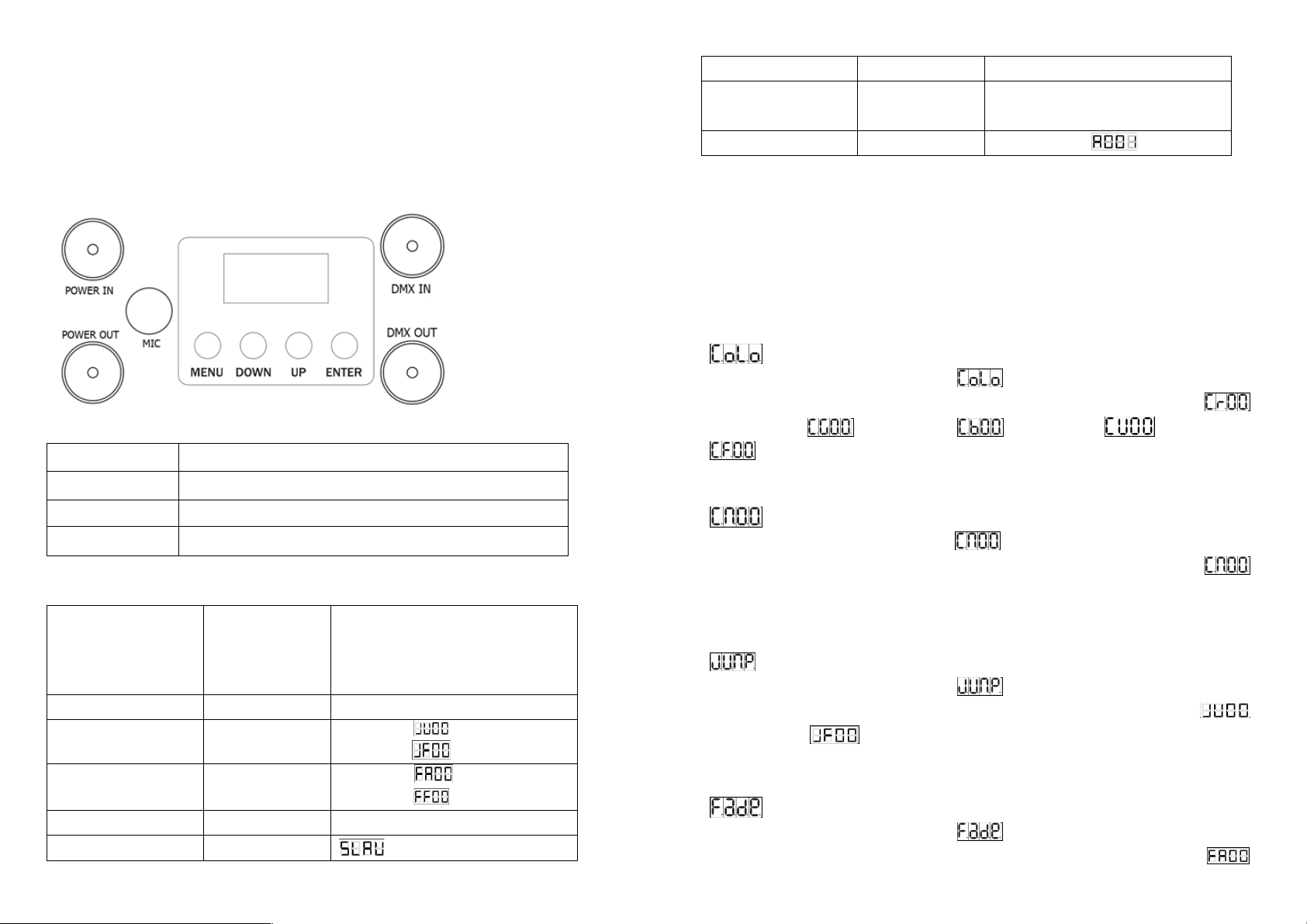
3.1 Control Panel
Buttons function of display
MENU
Selects the programming functions
DOWN
To go backward in the selected functions
UP
To go forward in the selected functions
ENTER
Confirms the selected functions
Led display menu
Colour mode
CoLo
Cr 00~99 (Red)
CG 00~99 (Green)
Cb 00~99 (Blue)
CU 00~99 (UV)
CF 00~99 (Colour flash speed)
Colour Mixing mode
Cn01
Cn 00~015
Jump mode
Junp
JU 00~99
JF 00~99 (Flash speed)
Fade mode
Fade
FA 00~99
FF 00~99 (Flash speed)
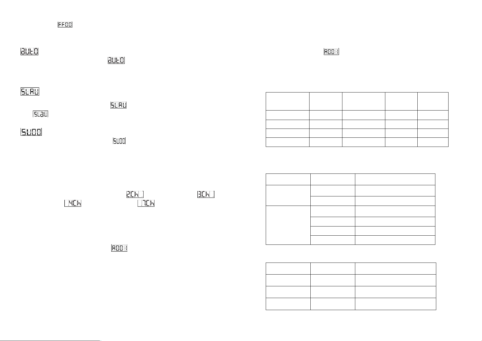
AUTO
aUTO
Slave mode
SLAV
Sound
SU00
SU 00~99 Sensitivity
Channel Mode
2CH/3CH/4CH/
7CH
2/3 channel mode
4/7 channel mode
DMX Address
A001
A001 – A512
3.2 Main Functions
To select any of the given functions, press the MENU button up to where the
required function is showing on the display. Select the function by pressing the
ENTER button and the display will blink. Use the DOWN and UP buttons to
change the mode. Once the required mode has been selected, press the
ENTER button to confirm.
Colour Mode
Press the MENU button to select Press the ENTER button and the
display will blink. Use the DOWN and UP buttons to select the
(Cr00-99) or (CG00-99) or (Cb00-99) or (CU00-99) or
(CF 00-99) mode. Once the mode has been selected, press the ENTER
button to confirm.
Colour mixing Mode
Press the MENU button to select . Press the ENTER button and the
display will blink. Use the DOWN and UP buttons to choose the
(Cn00-15) mode. Once the mode has been selected, press the ENTER button
to confirm.
Jump Mode
Press the MENU button to select Press the ENTER button and the
display will blink. Use the DOWN and UP buttons to select the
(JU00-99) or (JF00-99) mode. Once the mode has been selected,
press the ENTER button to confirm.
Fade Mode
Press the MENU button to select Press the ENTER button and the
display will blink. Use the DOWN and UP buttons to select the
(FA00-99) or (FF00-99) mode. Once the mode has been selected,
press the ENTER button to confirm.
Auto Mode
Press the MENU button to select . Press the ENTER button and the unit
will run a self-test with its built-in programs.
Slave mode
Press the MENU button to select . Press the ENTER button to confirm
and will be showed on the display.
Sound Mode
Press the MENU button to select . Press the ENTER button and the
display will blink. Use the DOWN and UP buttons to adjust the sound sensitivity
via the value 00-99. Once the value has been selected, press the ENTER
button to confirm.
Channel Mode
Press the MENU button to select the (2 Channel) mode, (3
Channel) mode, (4 Channel) mode or (7 Channel) mode via the
DOWN and UP buttons. Once the mode has been selected, press the ENTER
button to confirm.
4. DMX 512 Address setting
Press the MENU button to select . Press the ENTER button and the
display will blink. Use the DOWN and UP buttons to choose the (A001-A512)
address, press the ENTER button to confirm.
5. How to Control the unit
5.1. Master/slave built-in preprogram function
There is no need to turn the unit off when you change the DMX address as the
new DMX address setting will take effect at once.
5.2. Universal DMX Controller
By using a universal DMX controller to control the units, you will need to set a
DMX address from 1 to 512 so that the units can receive a DMX signal. Press
the MENU button until is showing on the display. Press the ENTER
button and the display will blink. Use the DOWN and UP buttons to change the
DMX 512 address. Once the address has been selected, press the ENTER
button to confirm.
Please refer to the below diagram to address your first 4 units:
Channel
mode
Unit 1
Address
Unit 2
Address
Unit 3
Address
Unit 4
Address
2 channel
1
3
5
7
3 channel
1
4
7
10
4 channel
1
5
9
13
7 channel
1
8
15
22
5.3 DMX 512 Configuration
2 CHANNEL MODE
Channel
Value
Function
1CH
000-240
Master dimmer
241-255
Strobe (slow-fast)
2CH
000-004
Blackout
005-080
Colour Macro
081-150
Colour Jump (slow-fast)
151-255
Colour Fade (slow-fast)
3 CHANNEL MODE
Channel
Value
Function
1CH
000-255
Red 0-100%
2CH
000-255
Green 0-100%
3CH
000-255
Blue 0-100%

4 CHANNEL MODE
Channel
Value
Function
1CH
000-255
Red 0-100%
2CH
000-255
Green 0-100%
3CH
000-255
Blue 0-100%
4CH
000-255
UV 0-100%
7 CHANNEL MODE
4. Optional IR Remote
Button functions:
The “BLACKOUT” button is used to set the LEDs into the power on or off
modes.
The “S PR” button is used to run the built-in programmes. To go though the
built-in programmes, press the “+” and “-” buttons.
The “FL” button is used to set the LEDs to flash on and off, to change the flash
fre-quency use the “+” and “-” buttons.
The “SP” button is used to set the run speed, this button is available only in the
colour change or colour fade modes. To change the speed use the “+” and “-”
buttons.
The “D” button is used to set the LEDs into DMX mode. (See DMX value table)
The “SA” button is used to set the LEDs into sound activated mode.
The “SL” button is used to set the LEDs into slave mode.
The “S”, “0”, “1”, “2”, “3”, “4”, “5”, “6”, “7”, “8” and “9” buttons are used
to set the DMX address for the LED’s.
Channel
Value
Function
1CH
000-255
Master dimmer
2CH
000-255
Strobe (slow-fast)
3CH
000-255
Red (0-100%)
4CH
000-255
Green (0-100%)
5CH
000-255
Blue (0-100%)
6CH
000-255
UV (0-100%)
7CH
000-004
No function
005-080
Colour Macro
081-150
Colour change (slow-fast)
151-255
Colour fade (slow-fast)

The “R”, “G”, “B” and “W” buttons are used to set the brightness for the Red,
Green, Blue and White/Amber/UV LEDs, to change the brightness use the “+”
and “-” buttons.
NOTE: See over leaf for DMX address set up examples. DMX Address
Examples:
To set the DMX address “245”;
1) Press the “S” button, this means you can now start to set the DMX address.
2) Press the “2” button, so the red LEDs flash, this means the first digit “2”
(the hundreds place) setting is successful.
3) Now Press the “4” button, and the green LEDs flash, this now means that
the second digit “4” (tens place) setting is successful.
4) Now Press the “5” button, and all of the R, G, B, A/W/UV LEDs flash, this
means that the final digit “5” (units place) setting is successful and the full
DMX address setting has been changed
5) Now press the “DMX MODE” button to save the new address into memory.
To set the DMX address “002”;
1) Press the “S” button, this means you can now start to set the DMX address.
2) Press the “0” button, so the red LEDs flash, this means the first digit “0”
(the hundreds place) setting is successful.
3) Now Press the “0” button, and the green LEDs flash, this now means that
the second digit “0” (tens place) setting is successful.
4) Now Press the “2” button, and all of the R, G, B, A/W/UV LEDs flash, this
means that the final digit “2” (units place) setting is successful and the full
DMX address setting has been changed.
5) Now press the “DMX MODE” button to save the new address into memory.
Important notes:
• Set the DMX address on each fixture before plugging into the DMX
controller.
• The I.R Remote is not usable when the fixture(s) are being controlled by
a DMX controller.
• The maximum transmitter distance is 10M. Please make sure that you
have the I.R remote aimed directly at each fixture to be programmed,
• If you do not press the “DMX MODE” button after you have changed the
DMX address, when you power down the fixture it will lose the address
you have set.
6. Troubleshooting
Following are a few common problems that may occur during operation
and some suggestions for easy troubleshooting:
A. The unit does not work, no light.
Check the connection of the power and the main fuse.
B. Not responding to DMX controller
1. Check DMX cables to see if linked correctly.
2. If the DMX address is showing but no response to the controller, check the
address settings and DMX polarity.
3. Try another DMX controller.
C. No response to the sound
Make sure the unit is not receiving a DMX signal.
7. Fixture Cleaning
•The cleaning of external optical lenses must be carried out periodically to
optimize light output. Cleaning frequency depends on the environment in
which the fixture operates: damp, smoky or particularly dirty surrounding
can cause a greater accumulation of dirt on the unit’s optics.
•Clean with a soft cloth using normal glass cleaning fluid or mild soapy
water.
•Always dry the parts carefully.
•Clean the external optics at least every 20 days.
-------------------------------------www.prolight.co.uk------------------------------------------
This manual suits for next models
1
Table of contents
Other PRO Light Lighting Equipment manuals


Popular Lighting Equipment manuals by other brands


MAGMATIC
MAGMATIC PRISMA MINI BAR 20 user manual

JB Systems
JB Systems LASER BURST II Operation manual

Kasco
Kasco WaterGlow LED4S19 Operation & maintenance manual

luceco
luceco LAC12P22S40 Installation & operating instructions

Robe
Robe Robin BMFL FollowSpot user manual

Lucci CONNECT
Lucci CONNECT GLASS GPO installation instructions

Conrad Electronic
Conrad Electronic 57 09 98 operating instructions

Nordic Aluminium
Nordic Aluminium XTSF manual

MOFLASH SIGNALLING
MOFLASH SIGNALLING X195 Series Installation & technical guide

Chauvet
Chauvet ST-800X supplementary guide

Banner
Banner A-GAGE MINI-ARRAY instruction manual

DHR
DHR 230RC Series Technical document