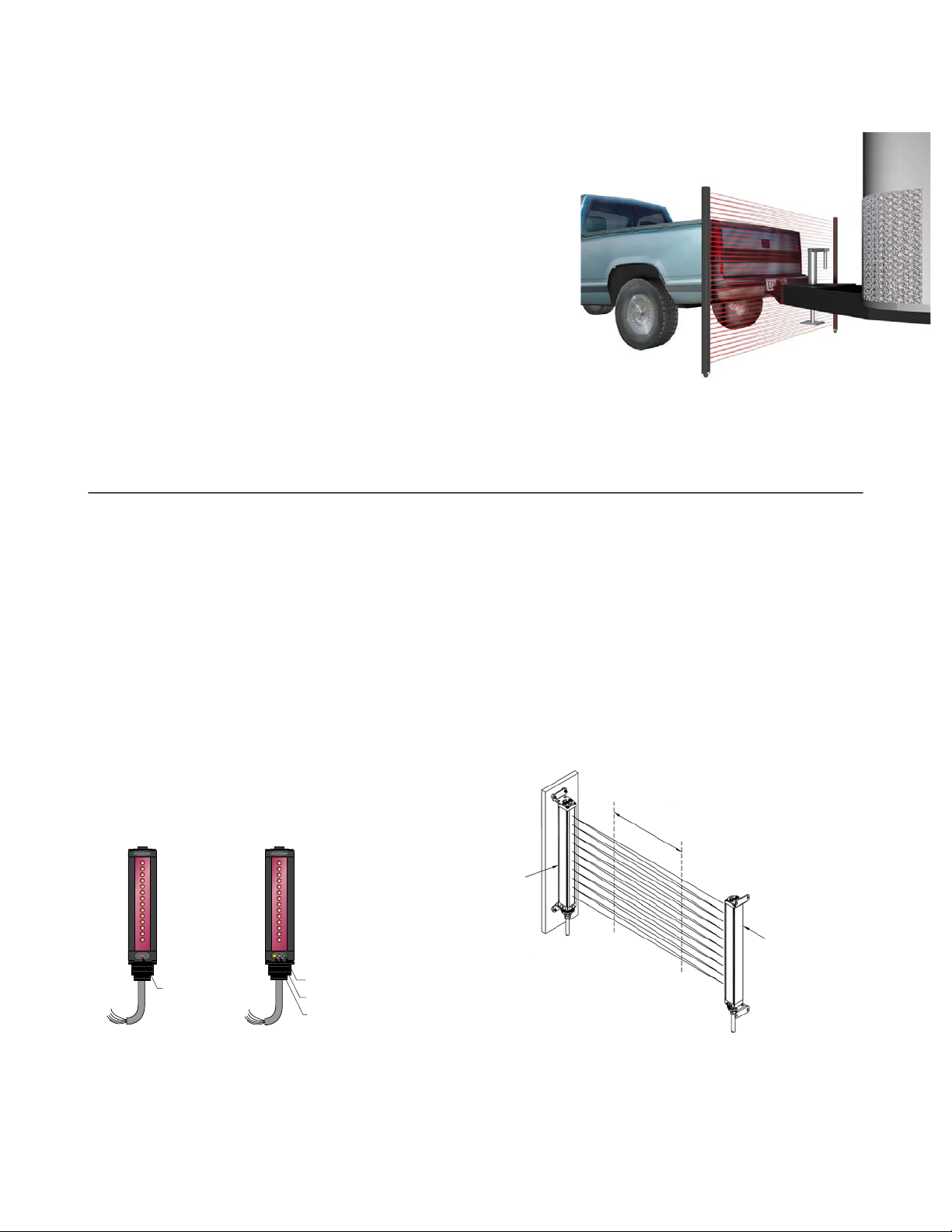
2.7 Vehicle Detection Applications (Output #1)
The MINI-ARRAY Two-Piece Light Screen features a superior interlaced (cross-hatched) beam pattern. When the light
screen is clear (no object is obstructing the receiver’s view of the emitted beam pattern), the sensor ignores small objects
while waiting to detect the beginning of a vehicle. Up to 125 mm (5 inch) of consecutive light channels must be blocked
before a valid object is detected; once the sensor detects 125 mm or more of consecutive blocked light, Output # 1
becomes active (output ON).
2.8 Trailer Hitch Detection Applications (Output #1)
After an object is detected, Output #1 remains active until the receiver again detects the entire emitter beam pattern (sensor
is clear). The interlaced scan pattern detects smaller objects after initially detecting a vehicle, even if only one beam is
obstructed. Once the receiver detects a fully unobstructed light screen, Output #1 again becomes inactive (output OFF).
2.9 System Self-Diagnostics
Output #2 can be configured for Alarm/Health Status. This enables advanced electronic and signal processing to allow the
receiver to continually monitor and evaluate light signal quality and alert the user to light signal degradation or sensor faults.
The sensor can detect marginal alignment, permanently blocked channels, a faulty emitter element, or a non-functioning
emitter.
The receiver was designed to detect system failures and remain operational. Potential problems include a dirty lens that
totally blocks (occludes) the optical light signal or a light signal failure (caused by either the emitter or receiver). Although
sensor failures are rare, the Two-Piece MINI-ARRAY is designed to continue to function while warning the user of fault
conditions. This minimizes system down time and provides advance notice that system maintenance or repairs are required.
Whenever the receiver detects proper operation, Output #2 is active (ON, a healthy condition). When the sensor detects a
system problem (either a sensor fault or a degraded signal), Output #2 is inactive (turns OFF, an alarm condition).
A system problem is acknowledged in three ways:
1. The condition of the diagnostic LEDs.
2. Output #2 will is inactive (OFF), when Output #2 is configured for Alarm/Health Status.
3. The condition can be transmitted to the monitoring system, via the EIA-485 interface (see
Request Sensor to
Transmit System Status Information (Command 0×66)
on page 12).
2.10 Marginal Alignment/Dirty Lens Detection
When the received light signal drops below a predetermined threshold, the receiver recognizes a marginal alignment or dirty
lens condition. The dirty lens threshold is equivalent to three times the minimum light signal necessary for detection.
Once this condition is detected, the receiver alerts the user that the lens surface should be cleaned or re-aligned. The
Amber diagnostic LED turns ON until the condition is no longer detected (whether the light screen is blocked or clear). This
advance recognition can be used to initiate a proper maintenance process. When Output #2 is configured for Alarm/Health
Status, Output #2 is inactive (OFF).
2.11 Fault Detection and Sensor Degradation Operation
The receiver detects an blocked (occluded) light channel when one or two consecutive light channels remain blocked after
eight or more vehicles are detected. After a blocked channel is detected, the Amber diagnostic LED flashes at 2 hertz, the
receiver notes the fault and begins to operate in sensor degradation mode. When Output #2 is configured for Alarm/Health
Status, Output #2 is inactive (OFF).
After the receiver detects a permanently blocked optical channel, it effectively ignores the degraded optical channel while
continuing to operate. This allows the sensor to continue working and, for many instances, provide reliable service.
Along with ignoring permanently blocked channels, the sensor continuously monitors sensor performance. If an optical
channel become inoperable (due to a faulty light channel), the sensor detects the problem and begins to operate in the
sensor degradation mode. Sensor degradation mode provides the user with advance notice of a fault while continuing to
maintain a functional traffic lane.
Emitter faults: The receiver can detect a non-functioning emitter (possibly caused by a disconnected cable). The receiver’s
Green and Red diagnostic LEDs flash at 2 hertz to signal this emitter condition.
A-GAGE®MINI-ARRAY®Two Piece Measuring Light Screen
www.bannerengineering.com - Tel: + 1 888 373 6767 7