PRO Light elumen8 User manual
Order codes: ELUM431
Fury 400 DTW 4 Cell Blinder
User Manual
www.prolight.co.uk Fury 400 DTW 4 Cell Blinder User Manual 2
Safety advice
WARNING
FOR YOUR OWN SAFETY, PLEASE READ THIS USER MANUAL
CAREFULLY BEFORE YOUR INITIAL START-UP!
• Before your initial start-up, please make sure that there is no damage caused during transportation.
• Should there be any damage, consult your dealer and do not use the equipment.
• To maintain the equipment in good working condition and to ensure safe operation, it is necessary
for the user to follow the safety instructions and warning notes written in this manual.
• Please note that damages caused by user modications to this equipment are not subject to warranty.
IMPORTANT:
The manufacturer will not accept liability for any resulting damages caused by the non-observance
of this manual or any unauthorised modication to the equipment.
OPERATING DETERMINATIONS
If this equipment is operated in any other way, than those described in this manual, the product may suffer damage and
the warranty becomes void. Incorrect operation may lead to danger e.g: short-circuit, burns and electric shocks etc.
Do not endanger your own safety and the safety of others!
Incorrect installation or use can cause serious damage to people and/or property.
CAUTION!
KEEP THIS EQUIPMENT
AWAY FROM RAIN,
MOISTURE AND LIQUIDS
CAUTION!
TAKE CARE USING
THIS EQUIPMENT!
HIGH VOLTAGE-RISK
OF ELECTRIC SHOCK!!
• Never let the power cable come into contact with other
cables. Handle the power cable and all mains voltage
connections with particular caution!
• Never remove warning or informative labels from the unit.
• Do not open the equipment and do not modify the unit.
• Do not connect this equipment to a dimmer pack.
• Do not switch the equipment on and off in short intervals,
as this will reduce the system’s life.
• Only use the equipment indoors.
• Do not expose to ammable sources, liquids or gases.
• Always disconnect the power from the mains when
equipment is not in use or before cleaning! Only handle
the power-cable by the plug. Never pull out the plug by
pulling the power-cable.
• Make sure that the available mains supply voltage is
between 100~240V AC, 50/60Hz.
• Make sure that the power cable is never crimped or
damaged. Check the equipment and the power cable
periodically.
• If the equipment has been exposed to drastic
temperature uctuation (e.g. after transportation),
do not connect power or switch it on immediately.
The arising condensation might damage the equipment.
Leave the equipment switched off until it has reached
room temperature.
• Never touch the xture during operation as it may be hot.
• If the equipment is dropped or damaged, disconnect the
mains power supply immediately and have a qualied
engineer inspect the equipment before operating again.
• If your product fails to function correctly, stop use
immediately. Pack the unit securely (preferably in the
original packing material), and return it to your Pro Light
dealer for service.
• Only use fuses of same type and rating.
• Repairs, servicing and power connection must only be
carried out by a qualied technician. THIS UNIT CONTAINS
NO USER SERVICEABLE PARTS.
• This lighting xture is for professional use only - it is not
designed for or suitable for household use. The product
must be installed by a qualied technician in accordance
with local territory regulations. The safety of the installation
is the responsibility of the installer. The xture presents
risks of severe injury or death due to re hazards, electric
shock and falls.
• Warning! Risk Group 2 LED product according to
EN 62471. Do not view the light output with optical
instruments or any device that may concentrate the beam.
• WARRANTY: Two years from date of purchase.

www.prolight.co.uk Fury 400 DTW 4 Cell Blinder User Manual 3
Product overview & technical specications
• 4 x 90W amber and warm white COB LEDs (1800K/3200K)
• RGB backlights for ‘eye-candy’ effects
• Beam angle: 50°
• 8,562 Lux @ 2m
• 12kHz refresh rate
• Individually addressable LEDs
• DMX channels: 1/4/4/7/9/18/20/23 or 27 selectable
• RDM (Remote Device Management)
• Static colour, colour change, colour fade, auto
and master/slave modes plus built-in programs
• 0-100% dimming and variable strobe
• 4 dimming curves: Linear, square law,
inverse square law and S-curve
• 4 button menu with OLED display
• PowerCON TRUE1 input/output
• IP rated 5-Pin XLR input/output
• Fan cooled
Fury 400 DTW 4 Cell Blinder
Specications Fury 400 DTW
Power consumption 395W
Power supply 100~240V, 50/60Hz
Fuse F6A 250V
IP rating IP65
Dimensions 398 x 398 x 215mm
Weight 11kg
Order code ELUM431
0m 1m 2m 3m 4m 5m
50° - Lux 35976 8994 3997
50°
2248 1439
The Fury IP65 rated blinders are loaded with 90W individually addressable amber and warm white COB LEDs,
which emulate the dimming and colour temperature of a halogen lamp. Each cell features an RGB backlight
creating a truly versatile series, ideal for rental and installation, backed up with the eLumen8 2 year warranty.
210mm
215mm
110mm
342mm
142mm
68mm
148mm
398mm
148 mm
398mm
IP65
www.prolight.co.uk Fury 400 DTW 4 Cell Blinder User Manual 4
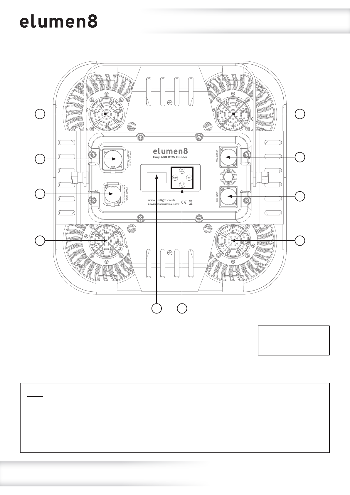
Technical specications
01 - OLED display
02 - Function buttons
03 - IP rated 5-Pin DMX input
04 - IP rated 5-Pin DMX output
05 - PowerCON TRUE1 input
06 - PowerCON TRUE1 output
07 - Fans
In the box: 1 x xture,
1 x power cable
& 1 x user manual
Fuse: The Fury 400 Blinder is tted with an internal mains (line) fuse. The fuse must only
be changed by qualied personnel. Before opening the xtures housing or changing the fuse,
the xture must be disconnected and isolated from the mains supply. Replacement cartridge
fuses must be of the same type and rating (20mm Glass F6A 250V). When closing the xture
please ensure the seal is correctly positioned and free from damage to ensure the xture is
water tight and to prevent water ingress.
POWER OUTPUT:
100-240V~50/60Hz POWER INPUT:
100-240V~50/60Hz
DMX INPUT DMX OUTPUT
www.prolight.co.uk
POWER CONSUMPTION: 395W
Fury 400 DTW Blinder
06
05
07
07
01 02
03
07
07
04

www.prolight.co.uk Fury 400 DTW 4 Cell Blinder User Manual 5
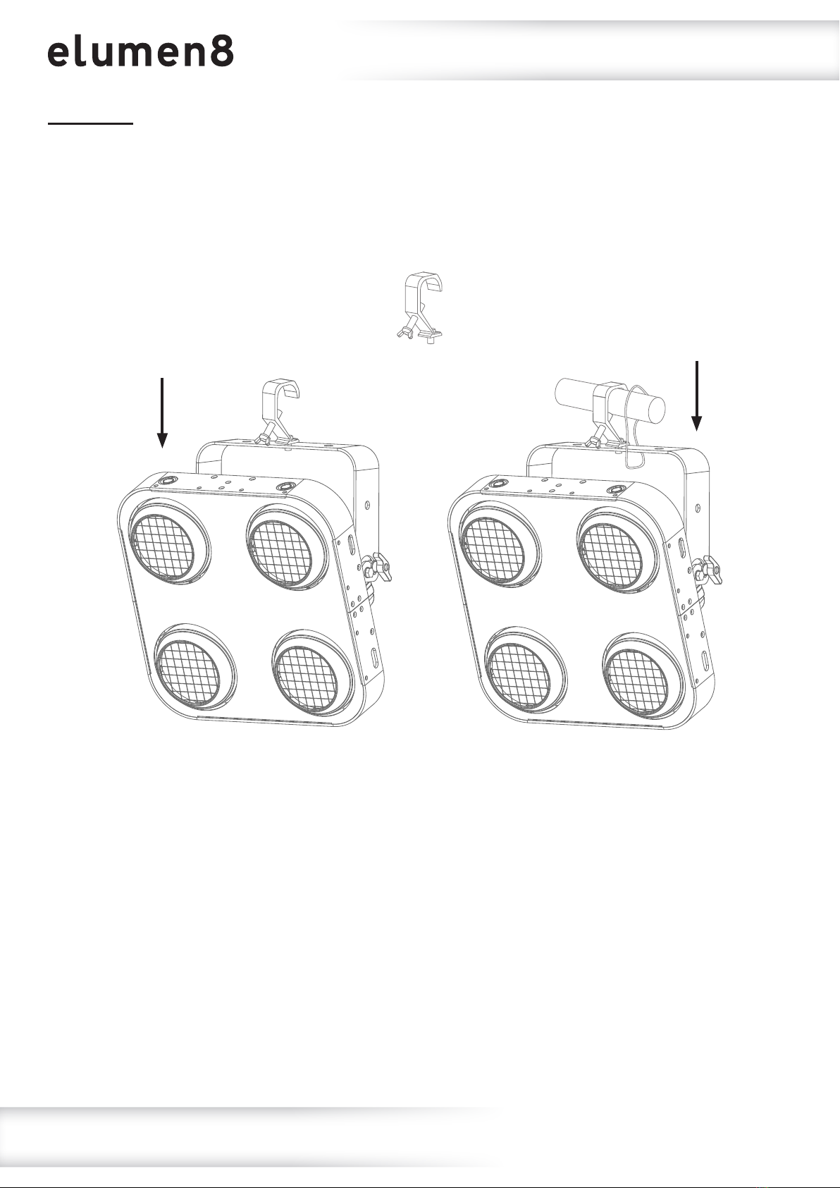
Installation
Before installing the xture, the supporting structure (ie. truss) must be able to hold a minimum of 10
times the xtures weight without any deformation (eg. 15kg - 150kg point load). The xture must be
secured with a secondary safety attachment when being installed (ie. an appropriate safety cable).
Never stand directly below the xture when mounting, removing, and/or servicing.
Overhead installation requires experience and qualications to calculate working load limits, the
material being used at the installation area and periodic safety inspections of the xture and installation
material. If you do not have the relevant experience and/or qualications please do not attempt the
installation yourself. The installation should be checked annually by a qualied person.
The eLumen8 Fury 400 can be operated in a number of mounting positions as shown in the diagram
above, hanging upside-down from the ceiling or truss, mounting sideways on truss or stood upright on
a at level surface. Always use a safety wire as an extra safety precaution to prevent damage/injury
in the event a clamp fails (see the next page for clamp installation). Never use the carry handles for
secondary attachments.
www.prolight.co.uk Fury 400 DTW 4 Cell Blinder User Manual 6
Installation
Installation:
1. Fasten the clamp to the xtures bracket.
2. Mount the xture onto your truss system via the clamps and tighten to ensure secure.
3. Pull the safety cable through the safety cable holes located on the metal base plate on the
underside of the xture and around the truss.
1
2
3

www.prolight.co.uk Fury 400 DTW 4 Cell Blinder User Manual 7
Operating instructions
Control Panel Menu:
The OLED control panel situated on the front of the xture allows the user to access the menu system to
adjust the xtures settings.
When the unit has been powered on the display will show “Versions” followed by “xx°C xx°C xx°C xx°C”.
The xture will then return to its home screen.
Pressing the “MODE” button once will take the user to the xtures main menu. Using the “UP” and
“DOWN” buttons you can then navigate between the different options in the main menu. Pressing the
“SET” button on one of these options allows you to access the sub menu where you can use the “UP”
and “DOWN” buttons to select option/value required. Once the option/value has been selected press
the “SET” button once more to conrm the setting.
To exit out of any of the above options, press and hold the “MENU” button.
MODE SET
DOWN
UP

www.prolight.co.uk Fury 400 DTW 4 Cell Blinder User Manual 8
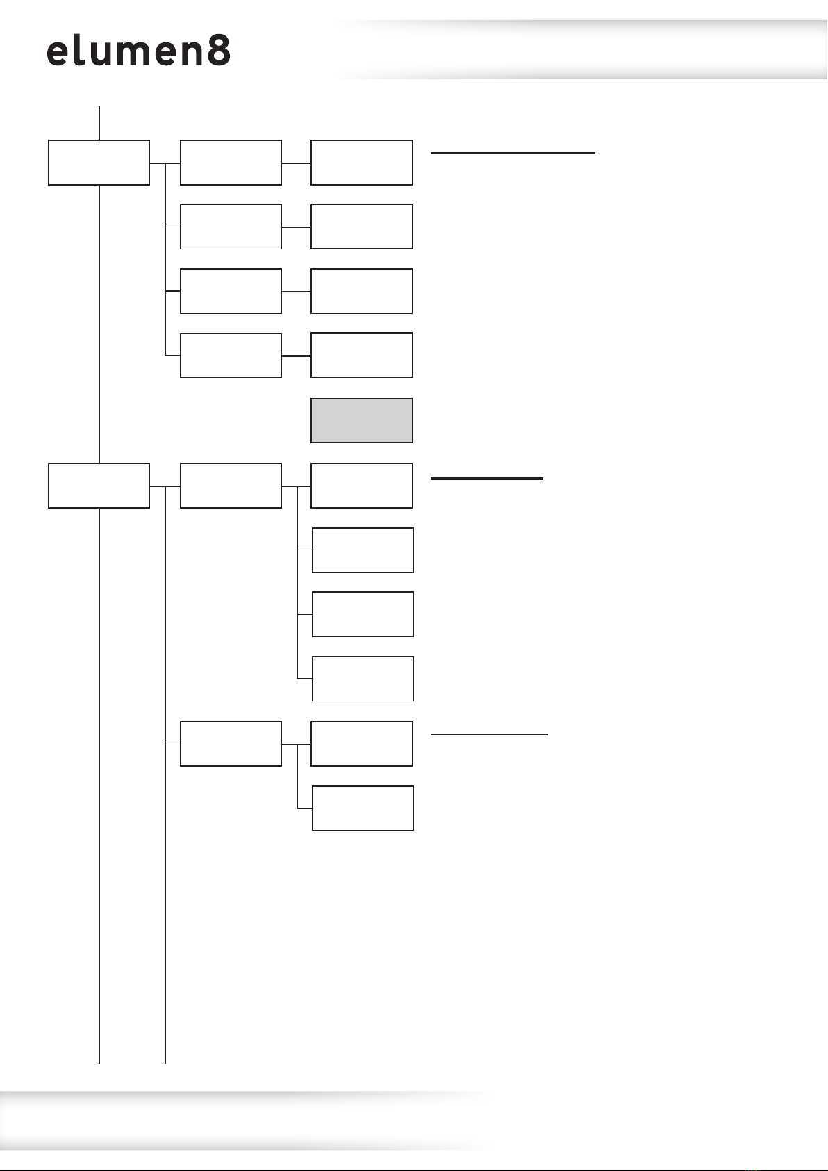
1: Auto Auto
Yes
Auto mode:
To access auto mode, press the “MODE” button
until “1: Auto” is highlighted on the OLED display.
Press the “SET” button and use the “UP” and
“DOWN” buttons to select between “Yes” and
“No”. Press the “SET” button to enter auto mode
when yes is selected.
Main Menu - Defaults are in grey
Built-in programs:
To access the built-in programs, press the
“MODE” button until “2: Program” is highlighted
on the OLED display. Press the “SET” button and
use the “UP” and “DOWN” buttons to highlight
“1) Mode”. Press the “SET” button and use the
“UP” and “DOWN” buttons to select the program
mode required between 01-23. Press the “SET”
button to conrm the setting.
If program mode 01 is selected use the “UP” and
“DOWN” buttons to highlight “2) Colour”. Press
the “SET” button and use the “UP” and “DOWN”
buttons to select the colour required between
01-21. Press the “SET” button to conrm the
setting.
If program mode 02-23 is selected use the “UP”
and “DOWN” buttons to highlight “2) Speed”.
Press the “SET” button and use the “UP” and
“DOWN” buttons to select the speed required
between 001-100. Press the “SET” button to
conrm the setting.
Now use the “UP” and “DOWN” buttons to
highlight “3) Strobe”. Press the “SET” button and
use the “UP” and “DOWN” buttons to select the
strobe speed required between 00-99.
Press the “SET” button to conrm the setting.
Operating instructions
Auto
No
2: Program Program
1) Mode:
Program Mode
xx
Program Speed
xx
Strobe Speed
xx
Colour Preset
xx
Program
2) Colour:
Program
2) Speed:
Program
3) Strobe:
IMPORTANT! PLEASE NOTE:The OLED display for this xture has a menu locking function where
after 30 seconds ofinactivity it will lock. To unlock the menu hold the “MODE” and “SET” buttons
for 3 seconds.

www.prolight.co.uk Fury 400 DTW 4 Cell Blinder User Manual 9
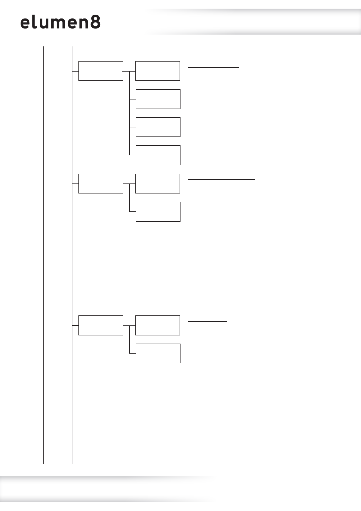
4: Slave Slave
Yes
DMX address:
To access the DMX address setting, press the
“MODE” button until “3: DMX” is highlighted on
the OLED display. Press the “SET” button and use
the “UP” and “DOWN” buttons to highlight
“1) Address”. Press the “SET” button and use
the “UP” and “DOWN” buttons to select the DMX
address required between 001-512. Press the
“SET” button to conrm the setting.
Slave mode:
To access slave mode, press the “MODE” button
until “4: Slave” is highlighted on the OLED
display. Press the “SET” button and use the “UP”
and “DOWN” buttons to select between “Yes”
and “No”. Press the “SET” button to enter slave
mode when yes is selected.
Main Menu - Defaults are in grey
DMX channel:
To access DMX channel mode, press the “MODE”
button until “3: DMX” is highlighted on the OLED
display. Press the “SET” button and use the “UP”
and “DOWN” buttons to highlight
“2) Channels”. Press the “SET” button and use
the “UP” and “DOWN” buttons to select the DMX
channel required 01/04/04/07/09/18/20/23
or 27 selectable. Press the “SET” button to
conrm the setting.
Operating instructions
Slave
No
3: DMX DMX
1) Address:
DMX Address
xxx
DMX Channels
xx
DMX
2) Channels:

www.prolight.co.uk Fury 400 DTW 4 Cell Blinder User Manual 10
5: Dimmer 1) White 1 White 1
xxx
B Ring
xxx
G Ring
xxx
R Ring
xxx
Amber 4
xxx
White 4
xxx
Amber 3
xxx
White 3
xxx
Amber 2
xxx
White 2
xxx
Amber 1
xxx
2) Amber 1
3) White 2
4) Amber 2
5) White 3
6) Amber 3
7) White 4
8) Amber 4
9) R Ring
10) G Ring
11) B Ring
Operating instructions
Default
000
Manual mode:
To access the manual dimming mode, press the
“MODE” button until “5: Dimmer” is highlighted
on the OLED display. Press the “SET” button
and use the “UP” and “DOWN” buttons to select
between White Pods 1-4, Amber Pods 1-4,
Backlight R, Backlight G or Backlight B.
Press the “SET” button and use the “UP” and
“DOWN” buttons to adjust the brightness
between 000-255.
Press the “SET” button to conrm the setting.
1
3
2
4
www.prolight.co.uk Fury 400 DTW 4 Cell Blinder User Manual 11
6: Halogen
7: Settings
1) Halogen 1
1) Curves Select
Halogen 1
xxx
1) Linear
Fast
Halogen 4
xxx
Halogen 3
xxx
Halogen 2
xxx
2) Halogen 1
2) Square Law
Smooth
3) Halogen 2
3) Inv Square
Law
4) Halogen 2
2) Dimmer
Speed
4) S-Curve
Operating instructions
Default
000
Manual halogen mode:
To access the manual halogen dimming mode,
press the “MODE” button until “6: Halogen” is
highlighted on the OLED display. Press the “SET”
button and use the “UP” and “DOWN” buttons to
select between Pods 1-4. Press the “SET” button
and use the “UP” and “DOWN” buttons to adjust
the brightness between 000-255.
Press the “SET” button to conrm the setting.
Dimming curve:
To access the dimming curve setting, press the
“MODE” button until “7: Settings” is highlighted
on the OLED display. Press the “SET” button and
use the “UP” and “DOWN” buttons to select
“1) Curves Select”. Press the “SET” button and
use the “UP” and “DOWN” buttons to select
between “Linear”,“Square Law”,“Inv Square
Law” and “S-Curve”. Press the “SET” button to
conrm the setting.
Dimming speed:
To access the dimming speed setting, press the
“MODE” button until “7: Settings” is highlighted
on the OLED display. Press the “SET” button and
use the “UP” and “DOWN” buttons to select
“2) Dimmer Speed”. Press the “SET” button
and use the “UP” and “DOWN” buttons to select
between “Fast” (LED) or “Smooth” (Halogen).
Press the “SET” button to conrm the setting.
www.prolight.co.uk Fury 400 DTW 4 Cell Blinder User Manual 12
Operating instructions
3) Dmx Fail 1) Blackout
Dmx Sync
On
Lock
On
2) Hold
Dmx Sync
Off
Lock
Off
3) Auto
4) Dmx Sync
5) Lock
4) Program
DMX fail setting:
Sets what the xture does when the DMX signal
is lost. To access the DMX fail setting, press the
“MODE” button until “7: Settings” is highlighted
on the OLED display. Press the “SET” button and
use the “UP” and “DOWN” buttons to select
“3) Dmx Fail”. Press the “SET” button and use
the “UP” and “DOWN” buttons to select between
“Blackout”,“Hold”,“Auto” and “Program”.
Press the “SET” button to conrm the setting.
Dmx synchronisation:
To access the DMX sync setting, press the
“MODE” button until “7: Settings” is highlighted
on the OLED display. Press the “SET” button and
use the “UP” and “DOWN” buttons to select
“4) Dmx Sync”. Press the “SET” button and use
the “UP” and “DOWN” buttons to select between
“On” and “Off”. Press the “SET” button to enable
Dmx sync when yes is selected.
Please note: The DMX Synchronisation setting
should be set to on when using the built-in
presets via DMX to ensure the xtures stay
synchronised.
Display lock:
To access the display lock setting, press the
“MODE” button until “7: Settings” is highlighted
on the OLED display. Press the “SET” button and
use the “UP” and “DOWN” buttons to select
“5) Lock”. Press the “SET” button and use the
“UP” and “DOWN” buttons to select between
“On” and “Off”. Press the “SET” button to enable
Display Lock when yes is selected.
Please note: After 30 seconds ofinactivity the
display will lock. To unlock the menu hold the
“MODE” and “SET” buttons for 3 seconds.

www.prolight.co.uk Fury 400 DTW 4 Cell Blinder User Manual 13
Operating instructions
Factory
Yes
Factory
No
6) Factory
Factory reset:
Resets all the xtures factory settings.
To access the factory setting reset, press the
“MODE” button until “7: Settings” is highlighted
on the OLED display. Press the “SET” button and
use the “UP” and “DOWN” buttons to select
“6) Factory”. Press the “SET” button and use the
“UP” and “DOWN” buttons to select between
“Yes” and “No”. Press the “SET” button to
perform the factory reset when yes is selected.
8: Information
Versions:
xx°C xx°C xx°C xx°C
UID:
Fixture information:
Displays the xtures version, each pods
temperature and RDM ID.
To display the xture information, press
the “MODE” button until “8: Information” is
highlighted on the OLED display. Press the
“SET” button and the xtures version, each pods
temperature and RDM ID will be displayed.

www.prolight.co.uk Fury 400 DTW 4 Cell Blinder User Manual 14
Operating instructions
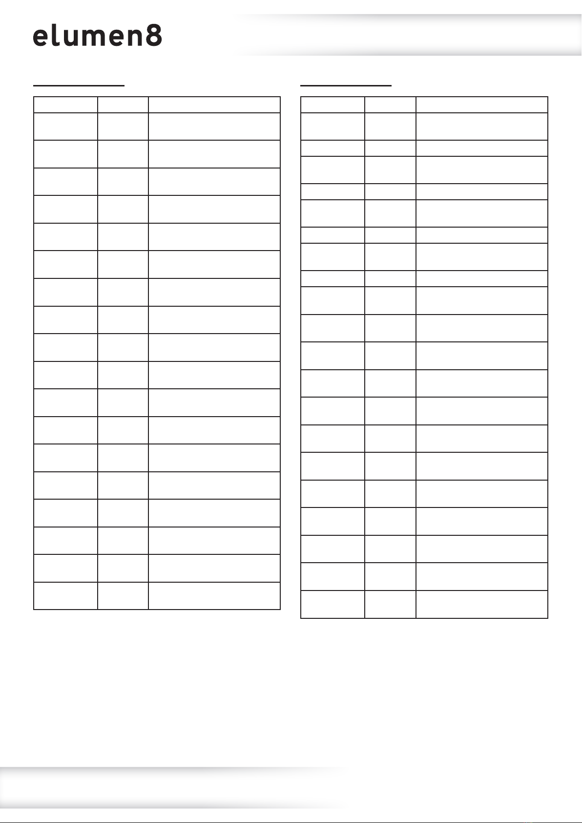
1 channel mode:
Channel Value Function
CH1 000-255 Halogen dimmer 0-100%
1
3
2
4
4 channel mode 1:
Channel Value Function
CH1 000-255 Halogen dimmer 0-100%
CH2 000-255 Red backlight dimmer 0-100%
CH3 000-255 Green backlight dimmer
0-100%
CH4 000-255 Blue backlight dimmer
0-100%
4 channel mode 2:
Channel Value Function
CH1 000-255 Pod 1 Halogen dimmer
0-100%
CH2 000-255 Pod 2 Halogen dimmer
0-100%
CH3 000-255 Pod 3 Halogen dimmer
0-100%
CH4 000-255 Pod 4 Halogen dimmer
0-100%
7 channel mode:
Channel Value Function
CH1 000-255 Pod 1 halogen dimmer
0-100%
CH2 000-255 Pod 2 halogen dimmer
0-100%
CH3 000-255 Pod 3 halogen dimmer
0-100%
CH4 000-255 Pod 4 halogen dimmer
0-100%
CH5 000-255 Red backlight dimmer 0-100%
CH6 000-255 Green backlight dimmer
0-100%
CH7 000-255 Blue backlight dimmer
0-100%
9 channel mode:
Channel Value Function
CH1 000-255 Halogen master dimmer
0-100%
CH2 000-255 Pod 1 halogen dimmer
0-100%
CH3 000-255 Pod 2 halogen dimmer
0-100%
CH4 000-255 Pod 3 halogen dimmer
0-100%
CH5 000-255 Pod 4 halogen dimmer
0-100%
CH6 000-255 Backlight master dimmer
0-100%
CH7 000-255 Red backlight dimmer 0-100%
CH8 000-255 Green backlight dimmer
0-100%
CH9 000-255 Blue backlight dimmer
0-100%
www.prolight.co.uk Fury 400 DTW 4 Cell Blinder User Manual 15
Operating instructions
18 channel mode:
Channel Value Function
CH1 000-255 Halogen master dimmer
0-100%
CH2 000-255 Pod 1 halogen dimmer
0-100%
CH3 000-255 Pod 2 halogen dimmer
0-100%
CH4 000-255 Pod 3 halogen dimmer
0-100%
CH5 000-255 Pod 4 halogen dimmer
0-100%
CH6 000-255 Backlight master dimmer
0-100%
CH7 000-255 Pod 1 red backlight dimmer
0-100%
CH8 000-255 Pod 1 green backlight dimmer
0-100%
CH9 000-255 Pod 1 blue backlight dimmer
0-100%
CH10 000-255 Pod 2 red backlight dimmer
0-100%
CH11 000-255 Pod 2 green backlight dimmer
0-100%
CH12 000-255 Pod 2 blue backlight dimmer
0-100%
CH13 000-255 Pod 3 red backlight dimmer
0-100%
CH14 000-255 Pod 3 green backlight dimmer
0-100%
CH15 000-255 Pod 3 blue backlight dimmer
0-100%
CH16 000-255 Pod 4 red backlight dimmer
0-100%
CH17 000-255 Pod 4 green backlight dimmer
0-100%
CH18 000-255 Pod 4 blue backlight dimmer
0-100%
20 channel mode:
Channel Value Function
CH1 000-255 Pod 1 warm white dimmer
0-100%
CH2 000-255 Pod 1 amber dimmer 0-100%
CH3 000-255 Pod 2 warm white dimmer
0-100%
CH4 000-255 Pod 2 amber dimmer 0-100%
CH5 000-255 Pod 3 warm white dimmer
0-100%
CH6 000-255 Pod 3 amber dimmer 0-100%
CH7 000-255 Pod 4 warm white dimmer
0-100%
CH8 000-255 Pod 4 amber dimmer 0-100%
CH9 000-255 Pod 1 red backlight dimmer
0-100%
CH10 000-255 Pod 1 green backlight dimmer
0-100%
CH11 000-255 Pod 1 blue backlight dimmer
0-100%
CH12 000-255 Pod 2 red backlight dimmer
0-100%
CH13 000-255 Pod 2 green backlight dimmer
0-100%
CH14 000-255 Pod 2 blue backlight dimmer
0-100%
CH15 000-255 Pod 3 red backlight dimmer
0-100%
CH16 000-255 Pod 3 green backlight dimmer
0-100%
CH17 000-255 Pod 3 blue backlight dimmer
0-100%
CH18 000-255 Pod 4 red backlight dimmer
0-100%
CH19 000-255 Pod 4 green backlight dimmer
0-100%
CH20 000-255 Pod 4 blue backlight dimmer
0-100%

www.prolight.co.uk Fury 400 DTW 4 Cell Blinder User Manual 16
Operating instructions
23 channel mode:
Channel Value Function
CH1 000-255 Master dimmer 0-100%
CH2 000-010 No function
011-255 Strobe (slow-fast)
CH3 000-255 Pod 1 warm white dimmer
0-100%
CH4 000-255 Pod 1 amber dimmer 0-100%
CH5 000-255 Pod 2 warm white dimmer
0-100%
CH6 000-255 Pod 2 amber dimmer 0-100%
CH7 000-255 Pod 3 warm white dimmer
0-100%
CH8 000-255 Pod 3 amber dimmer 0-100%
CH9 000-255 Pod 4 warm white dimmer
0-100%
CH10 000-255 Pod 4 amber dimmer 0-100%
CH11 000-255 Backlight master dimmer
0-100%
CH12 000-255 Pod 1 red backlight dimmer
0-100%
CH13 000-255 Pod 1 green backlight dimmer
0-100%
CH14 000-255 Pod 1 blue backlight dimmer
0-100%
CH15 000-255 Pod 2 red backlight dimmer
0-100%
CH16 000-255 Pod 2 green backlight dimmer
0-100%
CH17 000-255 Pod 2 blue backlight dimmer
0-100%
CH18 000-255 Pod 3 red backlight dimmer
0-100%
CH19 000-255 Pod 3 green backlight dimmer
0-100%
CH20 000-255 Pod 3 blue backlight dimmer
0-100%
CH21 000-255 Pod 4 red backlight dimmer
0-100%
CH22 000-255 Pod 4 green backlight dimmer
0-100%
CH23 000-255 Pod 4 blue backlight dimmer
0-100%
www.prolight.co.uk Fury 400 DTW 4 Cell Blinder User Manual 17
Operating instructions
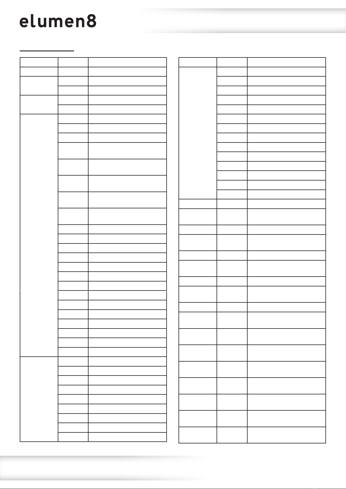
27 channel mode:
Channel Value Function
CH1 000-255 Master dimmer 0-100%
CH2 000-010 No function
011-255 Strobe (slow-fast)
CH3 000-010 No function
011-255 Random strobe (slow-fast)
CH4
000-010 No function
011-021 All pods - Warm white
022-032 All pods - Amber
033-043 Pod 1 & 3 - Warm white
Pod 2 & 4 - Amber
044-054 Pod 1 & 3 - Amber
Pod 2 & 4 - Warm white
055-065 Pod 1 & 2 - Warm white
Pod 3 & 4 - Amber
066-076 Pod 1 & 2 - Amber
Pod 3 & 4 - Warm white
077-087 All pods - Warm white
& Amber
088-098 All pods - Red
099-109 All pods - Green
110-120 All pods - Blue
121-131 All pods - Orange
132-142 All pods - Medium Yellow
143-153 All pods - Yellow
154-164 All pods - Magenta
165-175 All pods - Hot Pink
176-186 All pods - Cyan
187-197 All pods - Coral
198-208 All pods - Mint Green
209-219 All pods - Lilac
220-230 All pods - Dark Yellow
231-255 All pods - White (RGB)
CH5
000-015 No function
016-026 Program 2
027-037 Program 3
038-048 Program 4
049-059 Program 5
060-070 Program 6
071-081 Program 7
082-092 Program 8
093-103 Program 9
Channel Value Function
CH5 (cont.)
104-114 Program 10
115-125 Program 11
126-136 Program 12
137-147 Program 13
148-158 Program 14
159-169 Program 15
170-180 Program 16
181-191 Program 17
192-202 Program 18
203-213 Program 19
214-224 Program 20
225-235 Program 21
236-246 Program 22
247-255 Program 23
CH6 000-255 Program speed (slow-fast)
CH7 000-255 Pod 1 warm white dimmer
0-100%
CH8 000-255 Pod 1 amber dimmer 0-100%
CH9 000-255 Pod 2 warm white dimmer
0-100%
CH10 000-255 Pod 2 amber dimmer 0-100%
CH11 000-255 Pod 3 warm white dimmer
0-100%
CH12 000-255 Pod 3 amber dimmer 0-100%
CH13 000-255 Pod 4 warm white dimmer
0-100%
CH14 000-255 Pod 4 amber dimmer 0-100%
CH15 000-255 Backlight master dimmer
0-100%
CH16 000-255 Pod 1 red backlight dimmer
0-100%
CH17 000-255 Pod 1 green backlight dimmer
0-100%
CH18 000-255 Pod 1 blue backlight dimmer
0-100%
CH19 000-255 Pod 2 red backlight dimmer
0-100%
CH20 000-255 Pod 2 green backlight dimmer
0-100%
CH21 000-255 Pod 2 blue backlight dimmer
0-100%
CH22 000-255 Pod 3 red backlight dimmer
0-100%

www.prolight.co.uk Fury 400 DTW 4 Cell Blinder User Manual 18
Operating instructions
27 channel mode (cont.):
Channel Value Function
CH23 000-255 Pod 3 green backlight dimmer
0-100%
CH24 000-255 Pod 3 blue backlight dimmer
0-100%
CH25 000-255 Pod 4 red backlight dimmer
0-100%
CH26 000-255 Pod 4 green backlight dimmer
0-100%
CH27 000-255 Pod 4 blue backlight dimmer
0-100%
www.prolight.co.uk Fury 400 DTW 4 Cell Blinder User Manual 19
Setting the DMX address:
The DMX mode enables the use of a universal DMX controller. Each xture requires a “start address”
from 1- 512. A xture requiring one or more channels for control begins to read the data on the channel
indicated by the start address. For example, a xture that occupies or uses 7 channels of DMX and was
addressed to start on DMX channel 100, would read data from channels: 100, 101, 102, 103, 104,
105 and 106. Choose a start address so that the channels used do not overlap. E.g. the next unit in
the chain starts at 107.
DMX 512:
DMX (Digital Multiplex) is a universal protocol used as a form of communication between intelligent
xtures and controllers. A DMX controller sends DMX data instructions form the controller to the xture.
DMX data is sent as serial data that travels from xture to xture via the DATA “IN” and DATA “OUT”
XLR terminals located on all DMX xtures (most controllers only have a data “out” terminal).
DMX linking:
DMX is a language allowing all makes and models of different manufactures to be linked together
and operate from a single controller, as long as all xtures and the controller are DMX compliant.
To ensure proper DMX data transmission, when using several DMX xtures try to use the shortest
cable path possible. The order in which xtures are connected in a DMX line does not inuence the
DMX addressing. For example; a xture assigned to a DMX address of 1 may be placed anywhere in
a DMX line, at the beginning, at the end, or anywhere in the middle. When a xture is assigned a
DMX address of 1, the DMX controller knows to send DATA assigned to address 1 to that unit,
no matter where it is located in the DMX chain.
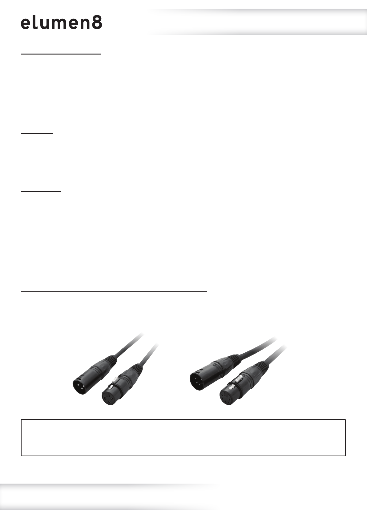
DATA cable (DMX cable) requirements (for DMX operation):
This xture can be controlled via DMX-512 protocol. The DMX address is set on the back of the unit.
Your unit requires either a standard 3-pin or 5-pin XLR connector for data input/output,
see images below.
Also remember that DMX cable must be daisy chained and cannot be split.
DMX setup
Further DMX cables can be purchased from all good sound and lighting suppliers or Prolight Concepts dealers.
Please quote: CABL10 – 2m CABL11 – 5m CABL12 – 10m3-Pin:
CABL185 – 2m CABL187 – 5m CABL188 – 10m5-Pin:
www.prolight.co.uk Fury 400 DTW 4 Cell Blinder User Manual 20
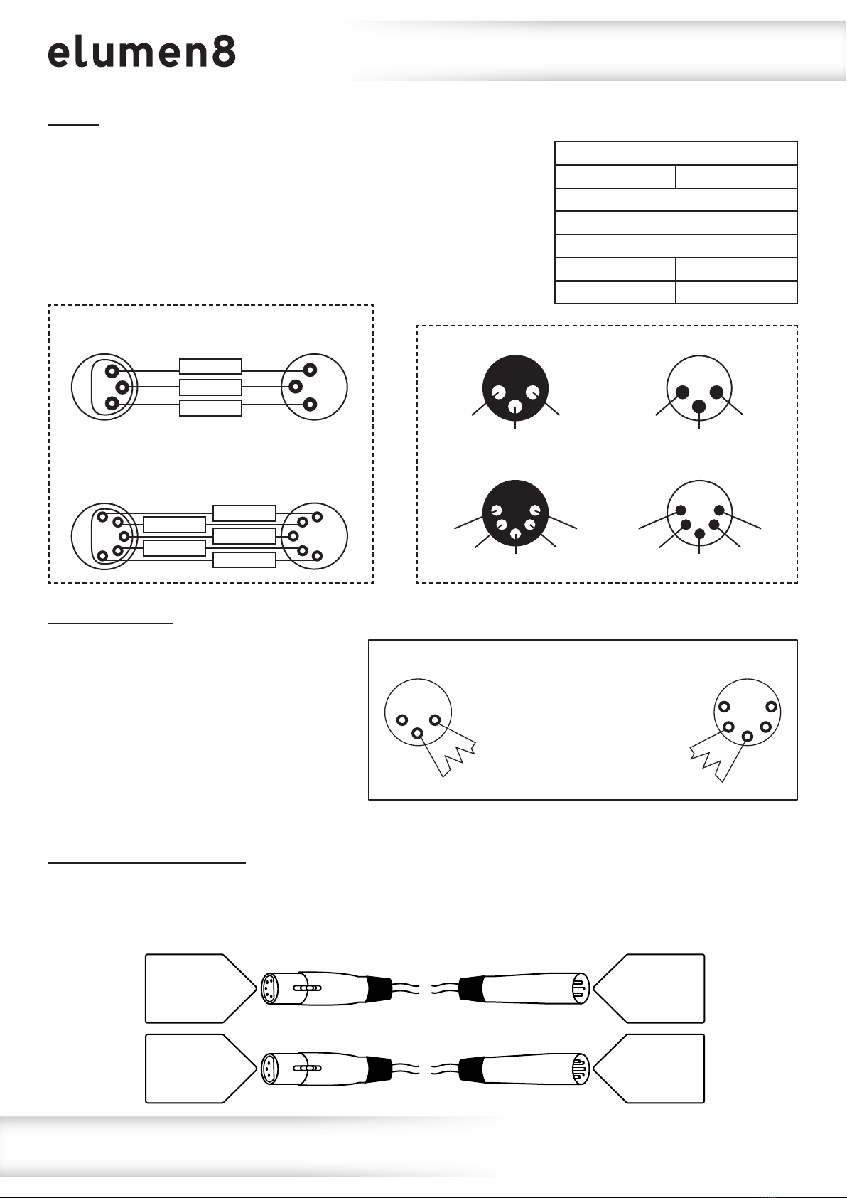
Notice:
Be sure to follow the diagrams below when making your own cables.
Do not connect the cables shield conductor to the ground lug or
allow the shield conductor to come in contact with the XLRs
outer casing. Grounding the shield could cause a short circuit
and erratic behaviour.
Line termination:
When longer runs of cable are used,
you may need to use a terminator on
the last unit to avoid erratic behaviour.
Using a cable terminator will decrease
the possibilities of erratic behaviour.
(3-pin - Order ref: CABL90,
5-pin - Order ref: CABL89)
5-pin XLR DMX connectors:
Some manufactures use 5-pin XLR connectors for data transmission in place of 3-pin. 5-pin XLR xtures
may be implemented in a 3-pin XLR DMX line. When inserting standard 5-pin XLR connectors in to a
3-pin line a cable adaptor must be used. The diagram below details the correct cable conversion.
5-pin XLR (female)
Pin 1: GND (screen)
Pin 2: Signal (-)
Pin 3: Signal (+)
Pin 4: N/C
Pin 5: N/C
3-pin XLR (female)
Pin 1: GND (screen)
Pin 2: Signal (-)
Pin 3: Signal (+)
3-pin XLR (male)
Pin 1: GND (screen)
Pin 2: Signal (-)
Pin 3: Signal (+)
5-pin XLR (male)
Pin 1: GND (screen)
Pin 2: Signal (-)
Pin 3: Signal (+)
Pin 4: N/C
Pin 5: N/C
DMX setup
Termination reduces signal
transmission problems and
interference. It is always
advisable to connect a DMX
terminal, (resistance 120
Ohm 1/4W) between pin 2
(DMX-) and pin 3 (DMX+) of
the last xture.
5-Pin
1
2 4
5
3
3-Pin
1 2
3
Pin Conguration
3-Pin 5-Pin
Pin 1 - Ground
Pin 2 - Negative
Pin 3 - Positive
– Pin 4 - N/C
– Pin 5 - N/C
1
2
3
1
2
3
DMX 512
3-Pin XLR output
DMX 512
3-Pin XLR input
GROUND
DMX +
DMX –
DMX 512
5-Pin XLR output
DMX 512
5-Pin XLR input
1
2
45
3
12
4
5
3
GROUND
N/C
DMX –
N/C DMX +
1 ground
3 hot
2 cold
3-Pin XLR male 3-Pin XLR female
2 cold
3 hot
1 ground
2 cold
1 ground 5 N/C
3 hot 4 N/C
5-Pin XLR male 5-Pin XLR female
4 N/C
5 N/C 1 ground
3 hot 2 cold
Other manuals for elumen8
1
Table of contents
Other PRO Light Lighting Equipment manuals


