PRO-NETS WR850RL User manual

WIRELESS 11n ROUTER
WR850RL
User’s Manual
September 2008

1
FCC Warning
This equipment has been tested and found to comply with the limits for a Class B digital device,
pursuant to part 15 of the FCC Rules. These limits are designed to provide reasonable
protection against harmful interference in a residential installation. This equipment generates,
uses, and can radiate radio frequency energy and, if not installed and used in accordance with
the instructions, may cause harmful interference to radio communication. However, there is no
guarantee that interference will not occur in a particular installation. If this equipment does
cause harmful interference to radio or television reception, which can be determined by turning
the equipment off and on, the user is encouraged to try to correct the interference by one or
more of the following measures:
Reorient or relocate the receiving antenna.
Increase the separation between the equipment and receiver.
Connect the equipment into an outlet on a circuit different from that to which
Consult the dealer or an experienced radio/TV technician for help. the receiver is
connected.
FCC Caution: Any changes or modifications not expressly approved by the party responsible
for compliance could void the user’s authority to operate this equipment.
This device complies with Part 15 of the FCC Rules. Operation is subject to the following two
conditions: (1) This device may not cause harmful interference, and (2) this device must
accept any interference received, including interference that may cause undesired operation.
IMPORTANT NOTE:
FCC Radiation Exposure Statement:
This equipment complies with FCC radiation exposure limits set forth for an uncontrolled
environment. This equipment should be installed and operated with a minimum distance of
about eight inches (20cm) between the radiator and your body.
This transmitter must not be co-located or operated in conjunction with any other antenna or
transmitter.!IEEE802.11b or 802.11g operation of this product in the USA is
firmware-limited to channels 1 through 11.
Notice
Changes or modifications to the equipment, which are not approved by the party responsible for
compliance could affect the user's authority to operate the equipment. Company has an on-going policy
of upgrading its products and it may be possible that information in this document is not up-to-date.
Please check with your local distributors for the latest information.

2
Copyright
2008 All Rights Reserved.
No part of this document can be copied or reproduced in any form without written consent from
the company.
Trademarks:
All trade names and trademarks are the properties of their respective companies.
Revision History
Revision History
V1 1st Release
You are cautioned that changes or modifications not expressly approved by the party responsible for compliance could void your
authority to operate the equipment.
FCC RF Radiation Exposure Statement:
1. This Transmitter must not be co-located or operating in conjunction with any other antenna or transmitter.
2. This equipment complies with FCC RF radiation exposure limits set forth for an uncontrolled environment. This equipment
should be installed and operated with a minimum distance of 20 centimeters between the radiator and your body.
This device complies with Part 15 of the FCC Rules. Operation is subject to the following two conditions: (1) this device may
not cause harmful interference and (2) this device must accept any interference received, including interference that may cause
undesired operation

3
Table of Contents
1. Introduction .......................................................................................5
1.1 Features ...................................................................................................... 5
1.2 Package Contents...................................................................................... 6
1.3 System Requirements ............................................................................... 6
1.4 LEDs Indication & Connectors of Wireless Router ................................ 6
1.5 Installation Instruction .............................................................................. 7
2. PC Configuration...............................................................................8
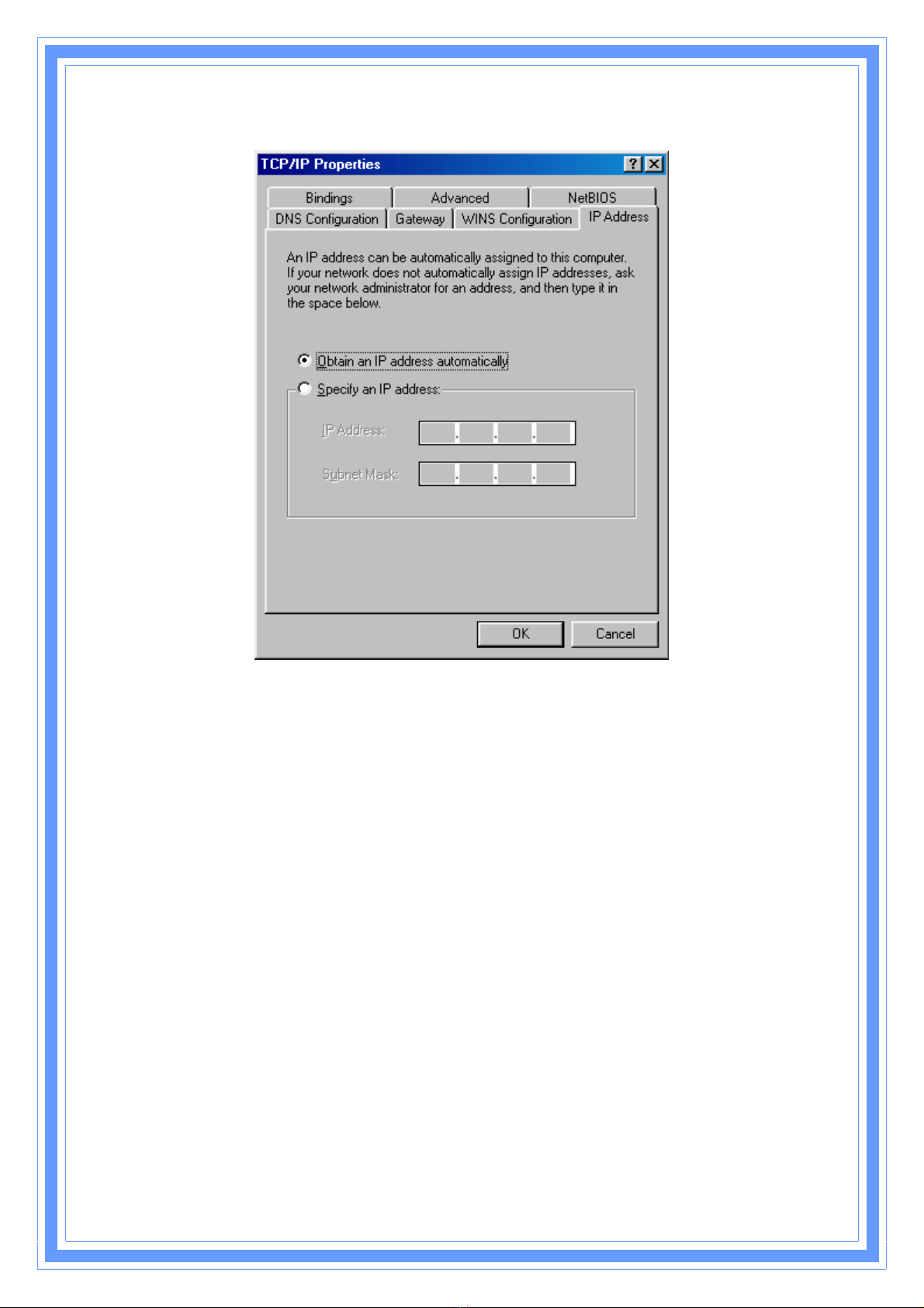
2.1 TCP/IP Networking Setup.......................................................................... 8
3. Configure Wireless Router via Web Based Utility .......................17
3.1 Access Web Based Configuration Utility .............................................. 17
3.2 Operation Mode ....................................................................................... 18
3.3 Quick Start................................................................................................ 27
3.4 Internet Settings....................................................................................... 27
3.4.1 WAN .............................................................................................. 27
3.4.2 LAN ............................................................................................... 28
3.4.3 DHCP Clients................................................................................ 30
3.4.4 VPN Passthrough ........................................................................ 31
3.4.5 DNS ............................................................................................... 31
3.4.6 Advanced Routing ....................................................................... 32
3.4.7 QoS ............................................................................................... 34
3.5 Wireless Settings ..................................................................................... 35
3.5.1 Basic ............................................................................................. 35
3.5.2 Advanced...................................................................................... 38
3.5.3 Security......................................................................................... 40
3.5.4 WPS............................................................................................... 42
3.5.5 Station list..................................................................................... 44
3.5.6 Site Survey ................................................................................... 44
3.6 Firewall...................................................................................................... 45
3.6.1 MAC/IP/Port Filtering Settings.................................................... 45
3.6.2 Port Forwarding ........................................................................... 47
3.6.3 DMZ ............................................................................................... 48
3.6.4 System Security Settings............................................................ 49
3.6.5 Content Filtering .......................................................................... 49
3.6.6 Port Trigger .................................................................................. 52
3.7 Administration.......................................................................................... 53
3.7.1 Administration.............................................................................. 53

4
3.7.2 Upgrade Firmware ....................................................................... 54
3.7.3 Setting Management.................................................................... 55
3.7.4 Status ............................................................................................ 56
3.7.5 Statistics ....................................................................................... 57
3.7.6 System Command ....................................................................... 58
3.7.7 System Log .................................................................................. 59

5
1. Introduction
This Wireless Broadband Router is a draft 802.11n compliant device that provide faster and
farther range than 802.11g while backward compatible with 802.11g and 802.11b devices.
This Router uses advanced broadband router chipset and wireless LAN chipset solution let
you enjoy high-speed Wired and Wireless connection. Simply connect this device to a Cable or
DSL modem and then you can share your high-speed Internet access with multiple PCs at
your home. It creates a secure Wired and Wireless network for you to share photos, files,
video, music, printer and network storage. This device also supports the latest wireless
security features such as WEP, WPA, WPA2 and WPS to prevent from unauthorized access.
1.1 Features
ΘʳCompliant with IEEE 802.11n draft 2.0 standard
ΘʳBackward compatible with IEEE 802.11b/g
ΘʳSupports NAT, NAPT, DHCP Server/Client
ΘʳSupports VPN pass through - IPSec, PPTP, L2TP
ΘʳSupports Virtual Server / Port Trigger / Port Forward
ΘʳSupports Virtual DMZ Host, DNS Proxy, DDNS, UPnP
ΘʳSupports 64/128-bit WEP Data Encryption
ΘʳSupports WPA / WPA2 / WPS / 802.1x Authentication
ΘʳSupports WDS (Wireless Distribution System) mode
ΘʳSupports Quality of Service (QoS) – WMM
ΘʳSupports MAC Filter, Client Filter, URL/IP Filter
ΘʳSupports Hacker Pattern Detection
ΘʳSupports Auto-crossover (MDI/MID-X) function
ΘʳSupports software upgrade through Web
ΘʳFriendly web-based GUI Configuration and Management

6
1.2 Package Contents
ΘʳOne Wireless AP Router with 2 antennas
ΘʳOne External Power Adapter
ΘʳOne CD-ROM (user’s manual)
ΘʳOne RJ-45 Ethernet Cable
1.3 System Requirements
ΘʳComputers with an installed Ethernet adapter.
ΘʳValid Internet Access account and Ethernet based DSL or Cable modem.
Θʳ10/100Base-T Ethernet cable with RJ-45 connector.
ΘʳTCP/IP protocol must be installed on all PCs.
ΘʳSystem with MS Internet Explorer ver. 5.0 or later, or Netscape Navigator ver. 4.7 or
later.
1.4 LEDs Indication & Connectors of Wireless Router
Front Panel LEDs Indication
LED Light Status Description
On Wireless Router is powered on.PWR
Off Wireless Router is powered off.
On Wireless Router is hung.Status
Blinking Wireless Router is up and ready.
On LAN port is successfully connected.LAN
(1, 2, 3, 4) Blinking Data is being sent or received.
On WAN port is successfully connectedWAN
Blinking Data is being sent or received.
Slow Blinking WLAN is successfully connected.WLAN
LINK/ACT Blinking Data is being sent or received.

7
Back Panel Connectors
Button/Port Description
Reset Reset configurations to default. You would use the reset button only when
a program error has caused your 11n AP router to hang. Press the button
and hold for 10 seconds.
WPS Click WPS button about 2-3 seconds while you are connecting a PC of
wireless adapter with WPS function (you must enable WPS’ PBC
function).
LAN
(1x, 2x, 3x, 4x)
Ethernet RJ-45 connector, connect to PC with a RJ-45 Ethernet cable.
WAN Ethernet RJ-45 connector, connect to WAN access device, such as the
Cable modem or ADSL modem.
PWR Power connector, connect to the power adapter packaged with the AP
router.
1.5 Installation Instruction
1) Power off 802.11n AP Router and DSL/Cable modem.
2) Connect computer to the LAN port on the Wireless Router with Ethernet cable.
3) Connect the DSL or Cable modem to the WAN port on the Wireless Router with
Ethernet cable.
4) Power on DSL or Cable modem first, then connect power adapter to the power jack
on the rear panel of Wireless Router and plug the power cable into an outlet.
5) Check LEDs.
a) Once power on Wireless Router, Power LED should be on.
b) LAN LED should be on for each active LAN connection.
c) The WAN LED should be on when the DSL or cable modem is connected.
Warning: Only use the power adapter is provided from this package, use other power adapter
may cause hardware damage

8
2. PC Configuration
To communicate and configure 802.11n AP router, the PC on your LAN must install TCP/IP
protocol. Make sure the TCP/IP protocol of the PC is configured for Obtain IP address from
DHCP and is connected to LAN (Ethernet) port of the AP router. In doing so, the PC obtains an
IP address of 192.168.1.1 from 802.11n AP router.
The 802.11n AP router assumes an IP address of 192.168.1.1 without network connectivity.
This IP address is used for communicating with the 802.11n AP router via the web UI or Telnet,
with the PC connected to the LAN port.
The 802.11n AP router assumes a DHCP IP address on the WAN side if connected to the
network. In this case user can communicate with the same IP address 192.168.1.1 with PC
connected to the LAN port. PC in the network can communicate with the DHCP IP address
allocated to 802.11n router.
2.1 TCP/IP Networking Setup
Checking TCP/IP Settings for Windows 9x/Me
a) Select “Start ÆControl Panel ÆNetwork”, the window below will appear,

9
b) Click “Properties”, the window below will appear and then click “IP Address” tab,
ΘʳIf you decide to use DHCP, select “Obtain an IP address automatically”, then
click “OK” to confirm your settings. Once you restart your system, Wireless
Router will obtain an IP address for this system.
ΘʳIf you decide to use fixed IP address for your system, select “Specify an IP
address”, and make sure that IP Address and Subnet Mask are correct.
c) Select “Gateway” tab and enter correct gateway address in “New gateway” field,
then click “Add”,
This manual suits for next models
1
Table of contents
Other PRO-NETS Network Router manuals


