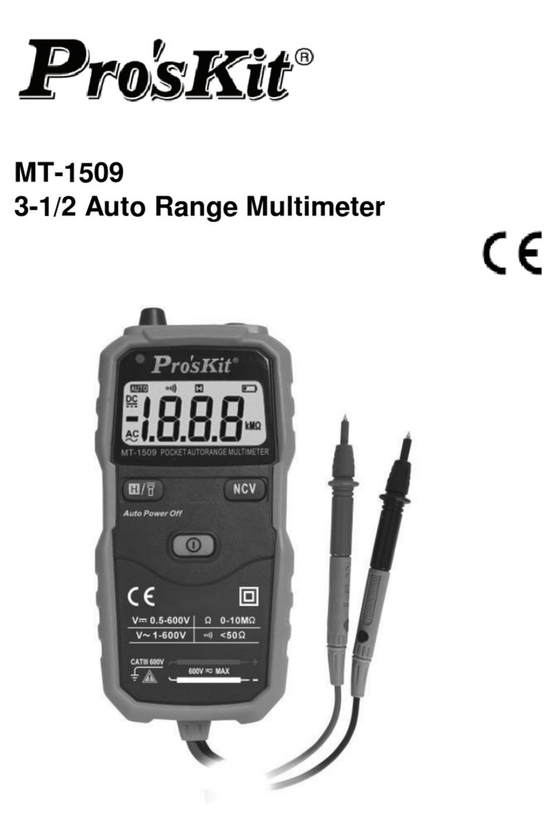
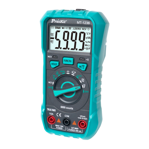
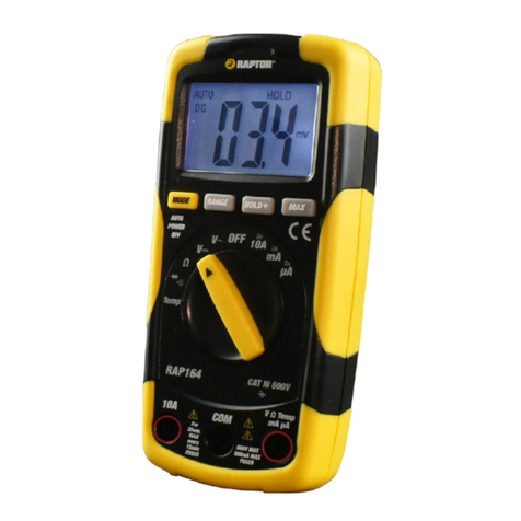
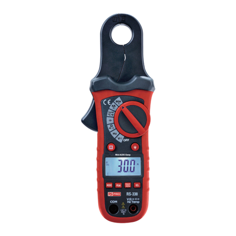
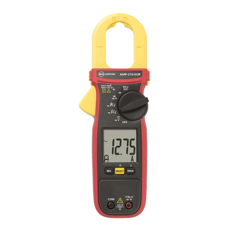
MT-1630 User Manual
1. SAFETY INFORMATION
Warning
Using this instrument should special attention to improper use may cause electric
shock or damage, in use should follow the usual safety rules and in full
compliance with the security measures provided for manual. In order to take full
advantage of instrument function and ensure the safe operation, please read these
instructions and follow them strictly
1.1 Preparation
1.1.1 Using the instrument the user must comply with standards of safety rules --
Electric shock protection --to avoid the misuse of instruments
1.1.2 When you received the instrument, check whether the damage in transit
1.1.3 Test lead and test probe must be in good condition connect the test lead before you
connect the test probe, when you disconnect them ,disconnect the test probe first
1.1.4 When servicing the meter use only specified replacement parts
1.1.5 Inspect the test lead for damaged insulation or exposed metal, check the test lead
and test probe for continuity. Replace damaged test lead before you use meter
2. FRONT PANEL DESRIPTION
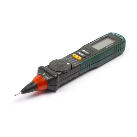
(1) “LIGHT” button
(2) “SELECT” button (3) Display 3 1/2
digits LCD with max
reading 1999
(4) “HOLD” button
(5) Function switch
(6) Scalable probe block
(7) Test probe
(8) Test lead
3. SPECIFICATIONS
Accuracy is specified for a period of one year after calibration and at 23±5℃with relative
humidity up to 75% 3.1 Review
Auto-Ranging
The max voltage the meter can measure is 600V DC or AC between COM and Earth
Ground
Working height: Max 2000m
Display: 3 1/2 –digit LCD
Max reading of 1999
Polarity: Auto polarity indication “-”expressed as negative polarity
Over range indication: ”OL” on display
Sampling Rate: Approximate 3 times per sec Functional
power unit display
Low battery indication “ ” on LCD
Fuse protection: mA: Resettable Fuse Auto shutdown:
15minutes
Battery: 1.5V2LR44
Operation Temperature 0
℃-40℃<80%RH
temperature: -10℃-50℃<70%RH Remove the batteryStorage
■20mA- 0.01mA ±(1.5%+10d)
■200mA- 0.01mA ±(1.5%+10d)
Continuity Test Diode
test
3.2 Use
3.2.1 Use the proper function and range for your measurements
3.2.2 When serving the meter, use the same model number or identical electrical
specification replacement parts
3.2.3 When using the probe s keep your fingers behind the finger guards on the unit
3.2.4 Do not input higher than 600V between the two meter’s input terminal to avoid
electric shock and damage to the meter
3.2.5 When the meter working at an effective voltage over 60V DC or 30V AC
(RMS),special care should be taken for there is danger of electric shock
3.2.6 Disconnect circuit power and discharge all high-voltage capacitors before testing
resistance, continuity and diode
3.2.7 Do not testing resistance, continuity and diode with electricity
3.2.8 Before pushing the function switch to charge functions disconnect test lead and
test probe from the circuit under test
3.2.9 Do not operate the meter around explosive gas .vapor or dust
3.2.10 Do not use the meter if it operates abnormally ,Protection may be impaired, when in
doubt have the meter serviced
3.2.11 Do not use the meter with the battery door or portions of the cover removed or
loosened
3.2.12 Do not store the meter in direct sunlight, high temperature and high humidity
4. OPERATION INSTRUCTION
4.1 Reading hold
After pressing “HOLD” button,the present reading will be held on the display ,to exit
from the mode ,just press button again
4.2 "SELECT" Button
This button is used for the function's change between: VDC/AC,
resistance/diode/continuity..
4.3 Auto Power-off
If the instrument is not used or stays in a range position for more than 15 minutes, the
power supply will be switched off and the instrument will be in sleep status. To arouse
the instrument from sleep, turn the function switch or press the "HOLD" button.
4.4 Measuring Voltage
4.4.1 Put away the test probe protective cover, and takes test lead from the back
box.
4.4.2 Set the function switch in V position
4.4.3 Press the "SELECT" button to set the unit in DC or AC range.
4.4.4 Connect the test probe and test lead across the source or load to be measured.
4.4.5 The display will show the reading along with the polarity of the test probe.
4.5.4 Connect the test lead and test probe across the resistance to be measured.
4.5.5 Read the value on LCD.
Note: - If the resistance is 2 1M, it takes several seconds to stabilize. It is normal.
- If the input terminal is in open circuit, overload mark will be displayed on LCD.
- Before measuring resistance, make sure that the power supply has been switched
off and all the capacitors have been discharged..
4.6 Measuring Diode
4.6.1 Put away the test probe protective cover.
4.6.2 Take test lead from the back box.
4.6.3 Set the function switch toposition.
4.6.4 Press "SELECT button to make the display show ~
4.6.5 Connect the test probe and test lead across the diode (test probe to the
positive pole of the diode, test lead to negative pole).
4.6.6 Read the forward voltage on LCD. Note:
- Meter shows an approximation of diode forward voltage drop - If the
instrument and test lead reverse connection, the LCD will show "OL". - If
the instrument and test lead open circuit, the LCD will show "OL".
4.7 Audible Continuity
4.7.1 Put away the test probe protective cover.
4.7.2 Take test lead from the back box.
4.7.3 Set the function switch to '' Ω’ position.
4.7.4 Press "SELECT button to make the display show “ ”
4.7.5 Connect the test lead and test probe across the resistance to be
measured.
4.7.6 The buzzer sounds if the resistance of a circuit under test is less than
50Ω; it may or may not sounds if the resistance of a circuit under test is
between 50Ωto 120Ω; it does not sound if the resistance of a circuit under
test is higher than 120.
Note:
- If the test lead reverse connection or the resistance is higher than 200Ω, the LCD will
show "OL". 4.8 Current measurement
Warning
Risk of electric shock.
When current measurement has been completed, disconnect the connection
between the conductor under test and the jaw, and remove the conductor away from
the transformer jaw of the Meter.
4.8.1 Put away the test probe protective cover. And take test lead from the back box.
4.8.2 Set the function switch in mA position
4.8.3 Press the "SELECT button to set the unit in DC or AC range.
4.8.4 Connect the test probe and test lead across the source or load to be measured. 4.8.5
The display will show the reading along with the polarity of the test probe.
5. MAINTENANCE
Warning

