Pro-tec 193762 User manual

PRO-TEC SENTRY BUILDING
AWNING MANUAL
IMPORTANT - TO THE DEALER OR ERECTOR:
RETURN THIS MANUAL TO THE OWNER FOR THEIR FUTURE REFERENCE
SIOUX STEEL COMPANY, P.O. BOX 1265, SIOUX FALLS, SOUTH DAKOTA 571 1
1-800-557-4689
MANUAL NO. 193762
REV D/MRS 8/1/17 ECN 17-141

TABLE OF CONTENTS
SAFETY PAGE 2
TOOLS & EQUIPMENT PAGE 3
COMPONENTS PAGE 4
40' AWNING FRAME PAGE 5
50' AWNING FRAME PAGE 6
60' AWNING FRAME PAGE 7
70' AWNING FRAME PAGE 8
80' AWNING FRAME PAGE 9
90' AWNING FRAME PAGE 10
EAVE INSTALLATION PAGE 11
40' TO 50' RATCHET MOUNT INSTALLATION PAGE 12
60' TO 80' RATCHET MOUNT INSTALLATION PAGE 13
90' RATCHET MOUNT INSTALLATION PAGE 14
COVER SPLICE BRACKET PAGE 15
MAINTENANCE SCHEDULE PAGE 16-17
WARRANTY STATEMENTS PAGE 18
1

SAFETY
Watch for this symbol. It points out important safety
precautions. It means “Attention – Be Alert!”
DEFINITIONS:
CAUTION: Indicates a hazardous situation, which, if not avoided, could result in
minor or moderate injury.
WARNING: Indicates a hazardous situation, which, if not avoided, could result
in death or serious injury.
DANGER: Indicates a hazardous situation, which, if not avoided, will result in
death or serious injury.
When assembling building:
Use appropriate safety practices during assembly of building. Hard hats are
recommended to prevent injury to head. Gloves and other heavy clothing are
recommended to prevent cuts and abrasions to hands and other body parts.
Beware of all pinch points when assembling building components. Appropriate
erection equipment and proper training in the operation of this equipment, are
important factors for the safe erection of building. Reading, understanding, and
following the instructions in this book are also very important for the safe
assembly of this building. Sioux Steel Company includes all reasonable means
for accident prevention, except a safe and careful operator.
If any decals become damaged, detached, or illegible, contact your dealer or
Sioux Steel Company at (800)-557-4689 for free replacements.
After building is complete:
To assure building remains safe, follow the maintenance schedule found at the
end of this manual.
If building is damaged:
If damage to building occurs, access in or around building should be restricted to
inspection only. Immediately contact your dealer or Sioux Steel Warranty
Department at (800) 557-4689. Repair of damages should be implemented as
soon as practical, with appropriate PRO-TEC replacement parts.
2

TOOLS AND EQUIPMENT
Drilling Tools: Power drill
3/16” drill bit (for pilot drilling drill screws)
17/32” drill bit (for1/2" bolts)
3/8” power driver (for drill screws)
Measuring Tools: 25' Tape measure
Hand Tools: Socket & wrench size 3/8” & 3/4"
Impact Wrench (pneumatic or electric)
Special Tools: Movable scaffolding or man lift
Material (Customer Supplied):
Duct Tape
BOLT INSTALLATION
Bolts should be installed to a snug-tight condition, which is defined as: the
tightness attained by either a few impacts of an impact wrench or the full effort of
a worker with a wrench that brings the connected plates in to a firm contact.
3
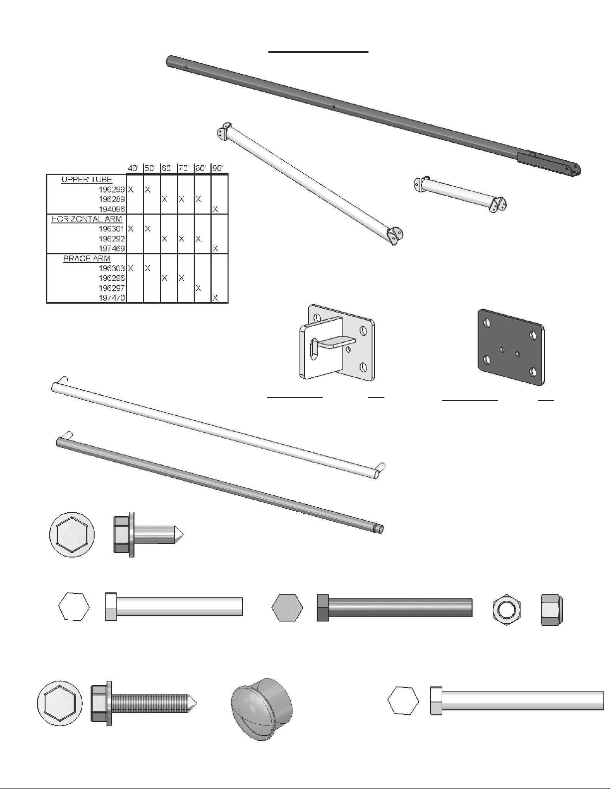
189285
3" TUBE CAP
187299
DRILL SCREW, 1/4" X 3/4"
EAVE 3"
193388GRY - 10FT
194098GRY - 12FT
189987GRY - 16FT
190006
1/2" x 3 1/2" BOLT
SCALE (1:2)
SWAGED EAVE 3"
193389GRY - 10FT
194100GRY - 12FT
189988GRY - 16FT
2" MOUNT
40' TO 80'
189992GRY
90'
194105GRY
UPPER TUBE
157630
DRILL SCREW, 1/4" x 1 1/4"
COMPONENTS
189515
1/2" NYLOCK
NUT SCALE (1:2)
2" MOUNT PLATE
(USED ON END
RAFTERS)
90'
194104GRY
40' TO 80'
189993GRY
BRACE ARM
163753
1/2" x 4" BOLT
SCALE (1:2)
191750
1/2" x 4 1/2" BOLT
SCALE (1:2)
HORIZONTAL ARM
4

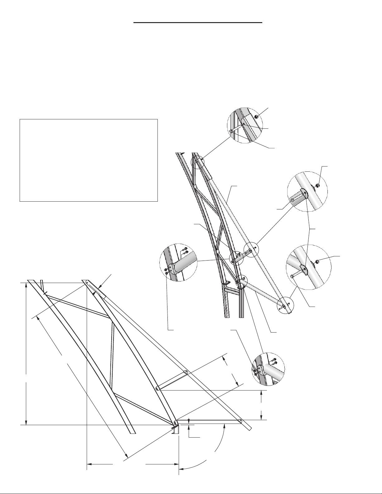
7'-5 1/8"
3'-8 1/8"
90.0°
1'-1 1/8"
8'-3 3/8"
4 1/2"
1'-1 1/2"
1 1/2"
HOLES
(3) 189515- 1/2" NYLOCK NUT
DRILL SCREWS
(8) 1/4" X 1 1/4"
(8) 157630- 1/4" X 1 1/4" DRILL SCREW
PRE-DRILLED
BOLT
1/2" X 3 1/2"
(1) 196301GRY HORIZONTAL ARM
(1) 196303GRY BRACE ARM
(1) 196299GRY UPPER TUBE
(3) 190006- 1/2" x 3 1/2" BOLT
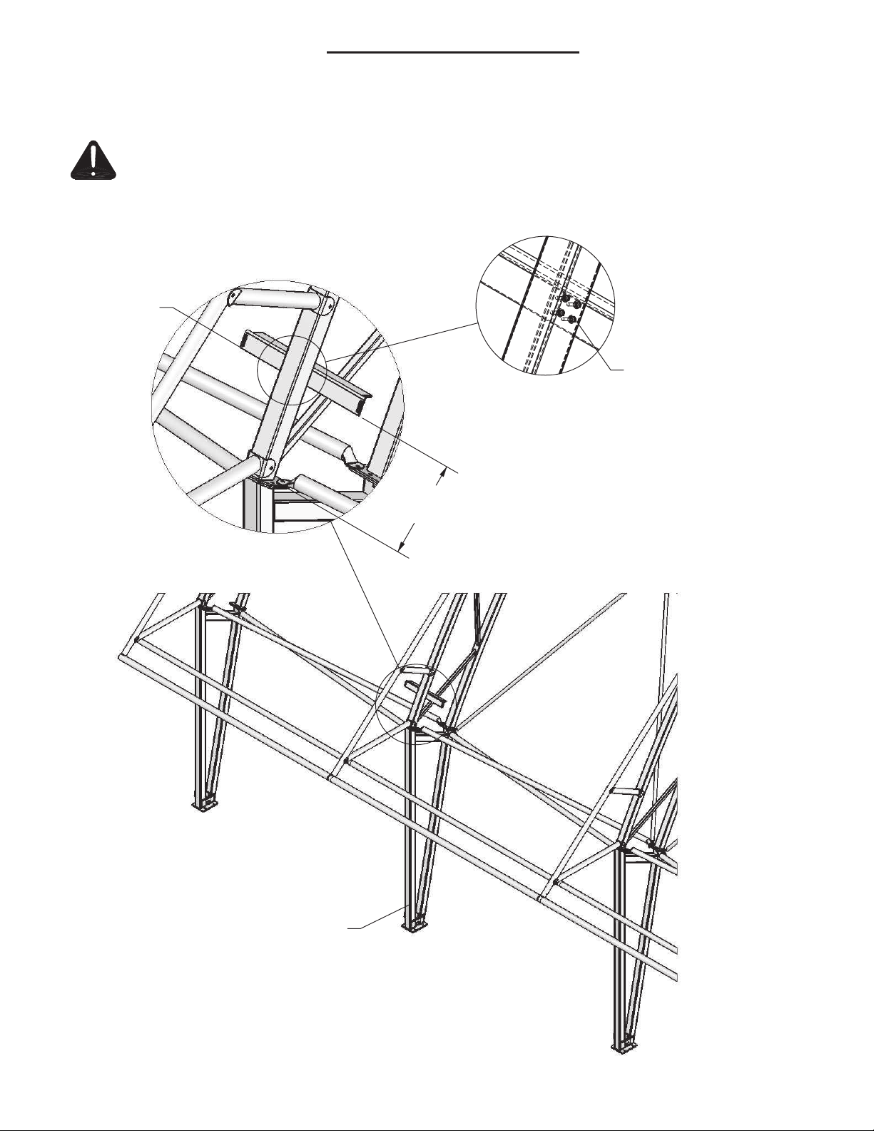
Step 1.1 Install Upper Tube as shown in drawing by drilling 17/32" clearance hole into rafter
and then securing with 1/2" bolt and nut.
Step 1.2 Assemble Horizontal Arm and Brace Arm to Upper Tube utilizing existing pre-drilled
holes and 1/2" bolts and nuts as shown in drawing.
Step 1.3 Utilizing 1/4" drill screws, attach Horizontal Arm and Brace Arm to rafter as shown
in drawing.
Step 1.4 Proceed to step 2.
STEP 1- 40' AWNING FRAMING
HOLE
DRILL 17/32"
1/2" NUT
UPPER
TUBE
ARM
HORIZONTAL
BRACE
ARM
1/2" NUT
1/2"
NUT
1/2" X 3 1/2"
BOLT
5

1/2" NUT
1/2"
NUT
1/2" X 3 1/2"
BOLT
HOLE
DRILL 17/32"
1/2" NUT
UPPER
TUBE
ARM
HORIZONTAL
BRACE
ARM
STEP 1- 50' AWNING FRAMING
(1) 196303GRY BRACE ARM
(1) 196299GRY UPPER TUBE
(3) 190006- 1/2" x 3 1/2" BOLT
(3) 189515- 1/2" NYLOCK NUT
(8) 157630- 1/4" X 1 1/4" DRILL SCREW
(1) 196301GRY HORIZONTAL ARM
Step 1.4 Proceed to step 2.
in drawing.
HOLES
PRE-DRILLED
BOLT
1/2" X 3 1/2"
DRILL SCREWS
(8) 1/4" X 1 1/4"
Step 1.1 Install Upper Tube as shown in drawing by drilling 17/32" clearance hole into rafter
and then securing with 1/2" bolt and nut.
Step 1.2 Assemble Horizontal Arm and Brace Arm to Upper Tube utilizing existing pre-drilled
holes and 1/2" bolts and nuts as shown in drawing.
Step 1.3 Utilizing 1/4" drill screws, attach Horizontal Arm and Brace Arm to rafter as shown
6

(1) 196289GRY UPPER TUBE
(1) 163753- 1/2" x 4" BOLT
(1) 196296GRY BRACE ARM
(2) 190006- 1/2" x 3 1/2" BOLT
STEP 1- 60' AWNING FRAMING
(1) 196292GRY HORIZONTAL ARM
(8) 157630- 1/4" X 1 1/4" DRILL SCREW
(3) 189515- 1/2" NYLOCK NUT
Step 1.4 Proceed to step 2.
in drawing.
HOLES
PRE-DRILLED
DRILL SCREWS
(8) 1/4" X 1 1/4"
BOLT
1/2" X 4"
Step 1.1 Install Upper Tube as shown in drawing by drilling 17/32" clearance hole into rafter
and then securing with 1/2" bolt and nut.
Step 1.2 Assemble Horizontal Arm and Brace Arm to Upper Tube utilizing existing pre-drilled
holes and 1/2" bolts and nuts as shown in drawing.
Step 1.3 Utilizing 1/4" drill screws, attach Horizontal Arm and Brace Arm to rafter as shown
1/2" NUT
1/2" X 3 1/2"
BOLT
1/2"
NUT
1/2" X 3 1/2"
BOLT
HOLE
DRILL 17/32"
1/2" NUT
UPPER
TUBE
ARM
HORIZONTAL
BRACE
ARM
7

(1) 196289GRY UPPER TUBE
(1) 163753- 1/2" x 4" BOLT
(8) 1/4" X 1 1/4"
(1) 196296GRY BRACE ARM
(2) 190006- 1/2" x 3 1/2" BOLT
STEP 1- 70' AWNING FRAMING
(1) 196292GRY HORIZONTAL ARM
(8) 157630- 1/4" X 1 1/4" DRILL SCREW
(3) 189515- 1/2" NYLOCK NUT
DRILL SCREWS
Step 1.4 Proceed to step 2.
in drawing.
HOLES
PRE-DRILLED
Step 1.1 Install Upper Tube as shown in drawing by drilling 17/32" clearance hole into rafter
and then securing with 1/2" bolt and nut.
Step 1.2 Assemble Horizontal Arm and Brace Arm to Upper Tube utilizing existing pre-drilled
holes and 1/2" bolts and nuts as shown in drawing.
Step 1.3 Utilizing 1/4" drill screws, attach Horizontal Arm and Brace Arm to rafter as shown
DRILL 17/32"
1/2" NUT
HOLE
1/2" X 4"
BOLT
UPPER
TUBE
ARM
HORIZONTAL
BRACE
ARM
1/2" NUT
1/2" X 3 1/2"
BOLT
1/2"
NUT
1/2" X 3 1/2"
BOLT
8

(1) 196289GRY UPPER TUBE
(1) 163753- 1/2" x 4" BOLT
(8) 1/4" X 1 1/4"
(1) 196297GRY BRACE ARM
(2) 190006- 1/2" x 3 1/2" BOLT
STEP 1- 80' AWNING FRAMING
(1) 196292GRY HORIZONTAL ARM
(8) 157630- 1/4" X 1 1/4" DRILL SCREW
(3) 189515- 1/2" NYLOCK NUT
DRILL SCREWS
Step 1.4 Proceed to step 2.
in drawing.
HOLES
PRE-DRILLED
Step 1.1 Install Upper Tube as shown in drawing by drilling 17/32" clearance hole into rafter
and then securing with 1/2" bolt and nut.
Step 1.2 Assemble Horizontal Arm and Brace Arm to Upper Tube utilizing existing pre-drilled
holes and 1/2" bolts and nuts as shown in drawing.
Step 1.3 Utilizing 1/4" drill screws, attach Horizontal Arm and Brace Arm to rafter as shown
UPPER
TUBE
ARM
HORIZONTAL
BRACE
ARM
DRILL 17/32"
1/2" NUT
HOLE
1/2" X 4"
BOLT
1/2" NUT
1/2" X 3 1/2"
BOLT
1/2"
NUT
1/2" X 3 1/2"
BOLT
9
(1) 194096GRY UPPER TUBE
(1) 191750- 1/2" x 4 1/2" BOLT
(8) 1/4" X 1 1/4"
(1) 197470GRY BRACE ARM
(2) 190006- 1/2" x 3 1/2" BOLT
STEP 1- 90' AWNING FRAMING
(1) 197469GRY HORIZONTAL ARM
(8) 157630- 1/4" X 1 1/4" DRILL SCREW
(3) 189515- 1/2" NYLOCK NUT
DRILL SCREWS
Step 1.4 Proceed to step 2.
in drawing.
HOLES
PRE-DRILLED
Step 1.1 Install Upper Tube as shown in drawing by drilling 17/32" clearance hole into rafter
and then securing with 1/2" bolt and nut.
Step 1.2 Assemble Horizontal Arm and Brace Arm to Upper Tube utilizing existing pre-drilled
holes and 1/2" bolts and nuts as shown in drawing.
Step 1.3 Utilizing 1/4" drill screws, attach Horizontal Arm and Brace Arm to rafter as shown
UPPER
TUBE
ARM
HORIZONTAL
BRACE
ARM
1/2" NUT
1/2" X 3 1/2"
BOLT
DRILL 17/32"
1/2" NUT
HOLE
1/2" X 4 1/2"
BOLT
1/2"
NUT
1/2" X 3 1/2"
BOLT
10
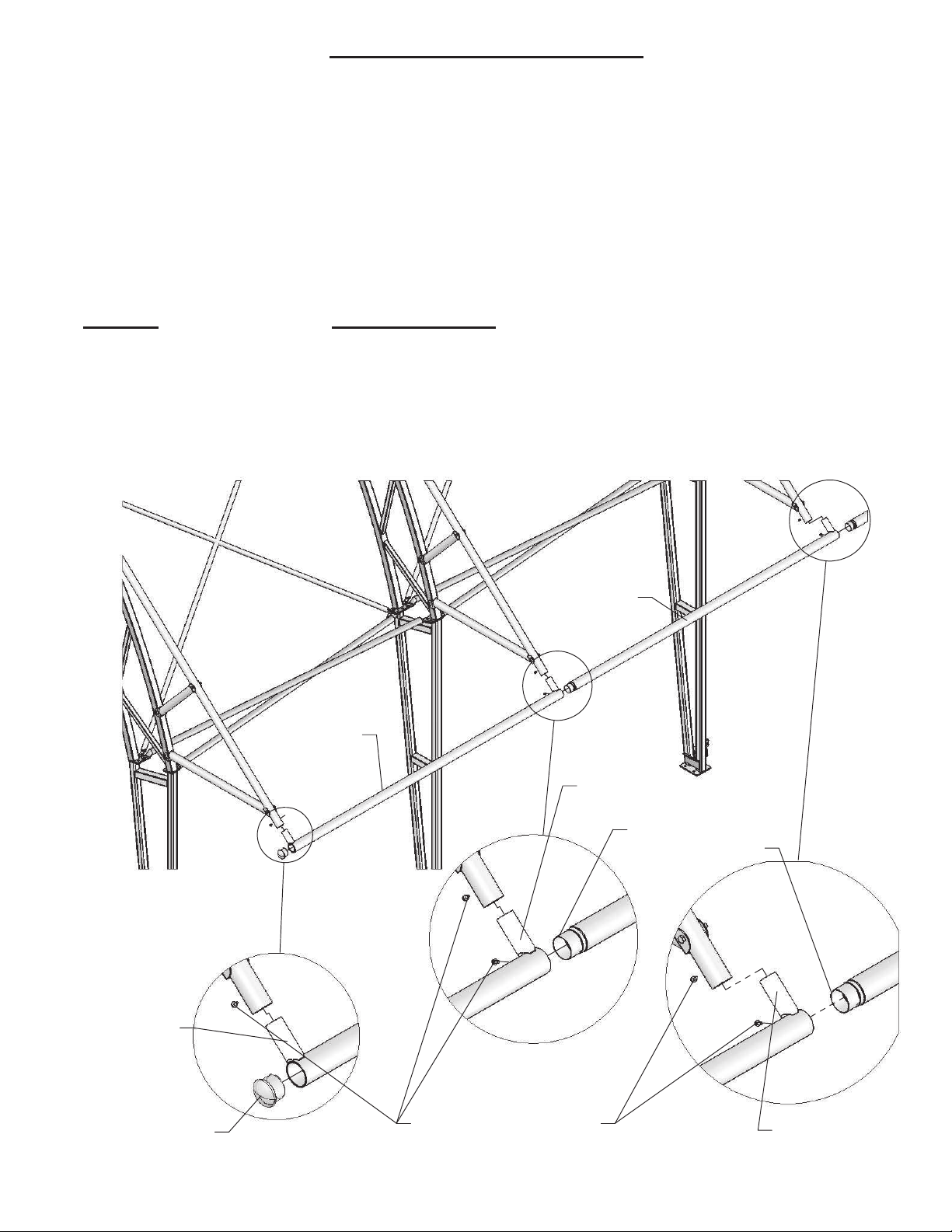
EAVE 3"
SWAGED
EAVE 3"
EAVE 3"
189987GRY- 16FT BAY
(187299)
CONNECTIONS
1/4" X 3/4"
DRILL SCREW
SWAGE
194098GRY- 12FT BAY
193388GRY- 10FT BAY
STEP 2- EAVE INSTALLATION
189988GRY- 16FT BAY
194100GRY- 12FT BAY
FROM UNDERNEATH
SWAGED EAVE 3"
193389GRY- 10FT BAY
Step 2.1 Starting at one end, install Eave 3" as shown in drawing. Secure with 1/4"
drill screws from underneath at insert connections.
Step 2.2 Next, install Swaged Eave 3" as shown in drawing. Secure with (2) 1/4" drill
screws from underneath at swage and insert connections .
Step 2.3 Install 3" Tube Caps into end of Eave Tubes as shown in drawing.
Step 2.4 Duct tape all drill screws and swage connections to prevent abrasion to cover.
3" TUBE CAP
(189285)
INSERT
CONNECTION
INSERT
CONNECTION
INSERT
CONNECTION
11

DRILL SCREW
(BOTH SIDES)
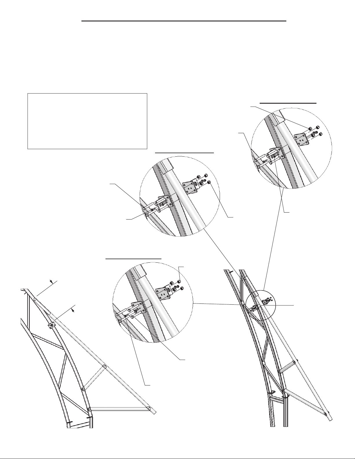
RH END RAFTER
NUT
NYLOCK
(4) 1/2"
(2) 1/4" X 1 1/4"
(4) 1/2" x 3 1/2"
BOLT
(4) 1/2" bolts and nuts. See drawing and LH & RH End Rafter detail below.
Step 3.2 Next, install (2) 2" Mounts to each Center Rafter by utilizing (4) 1/2" bolts and
STEP 3- 40' TO 50' RATCHET MOUNT INSTALLATION
nuts. See drawing and Center Rafter detail below.
Step 3.3 Next, secure 2" Mount Plates and 2" Mounts to rafter utilizing (4) 1/4"drill screws
as shown on drawing.
Step 3.1 Install (1) 2" Mount Plate and (1) 2" Mount to each End Rafter by utilizing
189993GRY- 2" MOUNT PLATE
189992GRY- 2" MOUNT
1/2" x 3 1/2" BOLT (190006)
1/2" NYLOCK NUT (189515)
1/4" x 1 1/4" DRILL SCREW (157630)
(4) 1/2"
NYLOCK
CENTER RAFTER
BOLT
(4) 1/2" x 3 1/2"
NUT
(2) 1/4" X 1 1/4"
DRILL SCREW
(BOTH SIDES)
(4) 1/2"
NYLOCK
LH END RAFTER
BOLT
(4) 1/2" x 3 1/2"
NUT
(2) 1/4" X 1 1/4"
DRILL SCREW
(BOTH SIDES)
12
Step 3.1 Install (1) 2" Mount Plate and (1) 2" Mount to each End Rafter by utilizing
(4) 1/2" bolts and nuts. See drawing and LH & RH End Rafter detail below.
Step 3.2 Next, install (2) 2" Mounts to each Center Rafter by utilizing (4) 1/2" bolts and
nuts. See drawing and Center Rafter detail below.
Step 3.3 Next, secure 2" Mount Plates and 2" Mounts to rafter utilizing (4) 1/4"drill screws
as shown on drawing.
189993GRY- 2" MOUNT PLATE
189992GRY- 2" MOUNT
1/2" x 4" BOLT (163753)
1/2" NYLOCK NUT (189515)
1/4" x 1 1/4" DRILL SCREW (157630)
STEP 3- 60' TO 80' RATCHET MOUNT INSTALLATION
(4) 1/2"
NYLOCK
NUT
RH END RAFTER
(2) 1/4" X 1 1/4"
DRILL SCREW
(BOTH SIDES)
(4) 1/2" x 4"
BOLT
LH END RAFTER
NYLOCK
NUT
(4) 1/2"
(2) 1/4" X 1 1/4"
DRILL SCREW
(BOTH SIDES)
(4) 1/2" x 4"
BOLT
NUT
CENTER RAFTER
NYLOCK
(4) 1/2"
(2) 1/4" X 1 1/4"
DRILL SCREW
(BOTH SIDES)
(4) 1/2" x 4"
BOLT
13

STEP 3- 90' RATCHET MOUNT INSTALLATION
(4) 1/2" bolts and nuts. See drawing and LH & RH End Rafter detail below.
as shown on drawing.
Step 3.2 Next, install (2) 2" Mounts to each Center Rafter by utilizing (4) 1/2" bolts and
nuts. See drawing and Center Rafter detail below.
Step 3.3 Next, secure 2" Mount Plates and 2" Mounts to rafter utilizing (4) 1/4"drill screws
Step 3.1 Install (1) 2" Mount Plate and (1) 2" Mount to each End Rafter by utilizing
194104GRY- 2" MOUNT PLATE
194105GRY- 2" MOUNT
1/2" x 4 1/2" BOLT (191750)
1/2" NYLOCK NUT (189515)
1/4" x 1 1/4" DRILL SCREW (157630)
DRILL SCREW
(BOTH SIDES)
RH END RAFTER
NUT
NYLOCK
(4) 1/2"
(2) 1/4" X 1 1/4"
(4) 1/2" x 4 1/2"
BOLT
(4) 1/2"
NYLOCK
LH END RAFTER
BOLT
(4) 1/2" x 4 1/2"
NUT
(2) 1/4" X 1 1/4"
DRILL SCREW
(BOTH SIDES)
(4) 1/2"
NYLOCK
CENTER RAFTER
BOLT
(4) 1/2" x 4 1/2"
NUT
(2) 1/4" X 1 1/4"
DRILL SCREW
(BOTH SIDES)
14
(4) 1/4" x 1 1/4"
DRILL SCREWS
(157630)
COVER SPLICE BRACKET
If structure requires multiple covers, install Mount Angle (193651GRY) on upper chord
of rafter at splice location as shown below utilizing (4) 1/4" x 1 1/4" Drill Screws (157630).
Note: Mount angle is used for 2" Conestoga ratchets at splice location. See Cover
manual for additional details.
DETAIL A
SCALE 1 : 16
193651GRY
MOUNT
ANGLE
1'-3 1/4"
APPROX
RAFTER AT
SPLICE LOCATION
15

MAINTENANCE SCHEDULE
1. One Week Inspection
a. The key visual indicator of adequate tension in the building fabric cover and end wall
panel is to ensure all creases and wrinkles in the fabric are removed. Check the ratchet
straps for tightness and adjust as necessary. Refer to step 9 of cover installation manual
for recommended torque settings for 1" and 2" ratchets.
b. Punctures in the fabric cover caused by accidental damage should be repaired
immediately. The fabric requires a product specific heat seam weld repair. Contact your
local Sioux Steel Pro-Tec® building dealer or manufacturer to schedule service.
c. Ensure all tension cables are taut. Cables should not sag. Adjust turnbuckles as
necessary.
2. Installation Adjustment
a. The building and end wall panels cover on your SIOUX PRO-TEC® Sentry Building
may relax after installation. It is critical to keep the cover taut (snug) over the rafters and
end wall panels taut over end wall framing to prevent wear and ensure a long life. Tighten
ratchets and adjust cables as required.
3. Annual Maintenance
a. Repeat 1 Week Inspection (listed above) a minimum of (4) times a year.
b. Visually inspect each cross cable for signs of wear and check turnbuckle tension.
Replace and/ or tighten as necessary.
c. Check all base plate anchor studs and nuts to assure they are tight.
d. Check all ratchet mount and winch bolts and nuts to assure they are tight.
e. Check for premature wear of fabric cover, especially where tension is applied and where
there is direct contact with the buildings steel frame.
f. Check for premature deterioration of the corrosion protection on the building components.
NOTE: Building covers and end wall panels installed in cooler weather may relax more
than covers installed in warm weather. Check tightness on covers and end wall panels
installed in cooler weather on the first available sunny day and adjust cables as
necessary. Severe weather conditions may also affect your cover, check cover after such
conditions occur.
NOTE: Failure to carry out above steps will invalidate the warranty.
WARNING: FLAMMABLE MATERIAL
EXPOSURE TO ANY HEAT SOURCE FOR ANY LENGTH OF TIME COULD RESULT IN DAMAGE TO
THE FABRIC COVER OR END PANEL MATERIAL. EXHAUST GASES, SPACE HEATER, WELDING
SPARKS, ETC. SHOULD NOT BE ALLOWED TO GET NEAR THE FABRIC PORTION OF
STRUCTURE. SIOUX STEEL COMPANY WILL NOT BE RESPONSIBLE FOR ANY DAMAGES OR
LIABILITIES RESULTING FROM FAILURE TO HEED THIS WARNING. THE COVER OR END PANEL
MATERIAL STARTS TO DETERIORATE AT EXPOSURE TO 180° TEMPERATURE FOR ANY
LENGTH OF TIME. PREVENT PROLONGED CONTACT FROM ANY HEAT SOURCE TO ENSURE
MAXIMUM PROTECTION TO THIS MATERIAL. FOR ANY FURTHER INFORMATION CONTACT
SIOUX STEEL COMPANY.
Revised 07/14/2017
N
EW
P
RODUCT
W
ARRANTY
P
RO
-T
EC
B
UILDINGS
LIMITED
WARRANTY
FOR
NEW
SIOUX
STEEL
COMPANY
PRODUCTS
A. GENERAL PROVISIONS
. “Sioux Steel” means Sioux Steel Company, 196 1/2 East Sixth Street, Sioux Falls, South Dakota 57104. The warranties
described below are provided by Sioux Steel to the original purchasers of new products purchased from Sioux Steel or from an authorized Sioux Steel Dealer
(the “Products”). Under these warranties, Sioux Steel will, at its option, repair or replace at its factory any Product covered under these warranties which is
found to be defective in material and workmanship during the applicable warranty term or refund the purchase price paid for the defective Product. Customer
will be responsible for labor charges for removing the defective Product and reinstalling the repaired or replacement Product, any premium charge for overtime
labor requested of Sioux Steel and shipping charges to and from Sioux Steel’s factory. These warranties are not transferrable.
B. WARRANTY PERIOD
. Subject to exclusions and limitations set forth herein, each new Product is warranted for the number of years specified
below.
Each warranty term begins from the date of purchase regardless of delay in receipt of the Product by Customer due to the time required to process, handle,
ship, assemble, construct and install the Product. Customer must retain proof of the date of purchase. Replacement parts for and repairs to the Product will
be warranted only for the remainder of the original warranty term. The replacement parts for or repairs to the Product will not extend the warranty term beyond
the original warranty term. Products described below include all parts, components and accessories.
PROTEC BUILDINGS
Pro-Tec Poultry Buildings 1 Year
Safeguard Livestock Shade 1 Year
Pro-Tec Single Tube (24’, 30’, and 36’) Buildings 3 Years
All Other Powder-Coated Pro-Tec Buildings in Livestock (other than Poultry) and Chemical Storage Applications 7 Years, Prorated Monthly
All Other Powder-Coated Pro-Tec Buildings Except those in Livestock and Chemical Storage Applications 15 Years, Prorated Monthly
All Other Hot-Dip Galvanized Pro-Tec Buildings 15 Years, Prorated Monthly
Fabricated Tarp Materials (covers)
15 Years, Prorated Monthly
Fabricated Tarp Materials for End Panels (All Pro-Tec Buildings) ; Rollup Sides; Curtains and Doors; Track Doors; Quarter
Panels and Half Moon End Panels ( On all Building Models) 3 Years, Prorated Monthly
Proration credit will be given toward the purchase price for the replacement of fabric and tarp materials, based on Sioux Steel’s current price list at the time the
warranty claim is made. 15 Year Proration Schedule: 7 Year Proration Schedule:
Year 1 = 93% Year 4 – 73% Year 7 – 53% Year 10 = 33% Year 13 = 13% Year 1 = 86% Year 4 = 43% Year 7 = 0%
Year 2 = 87% Year 5 = 67% Year 8 = 47% Year 11 = 27% Year 14 = 7% Year 2 = 72% Year 5 = 29%
Year 3 = 80% Year 6 = 60% Year 9 = 40% year 12 = 20% Year 15 = 0% Year 3 = 58% Year 6 = 15%
Exclusions specific to Pro-Tec Buildings: Damage or loss of any kind from (1) exposure of the fabric cover or end panel material to any heat source for any
length of time; (2) a failure to properly compact and engineer soils; (3) a failure to properly construct footings and foundations; and (4) exposure to conditions
in excess of the design wind and snow load specifications. NOTICE: Caustic and corrosive environments can result from live animal operations or
storage of caustic materials. Sioux Steel reserves the right to exclude from warranty under D(4) if conditions are deemed by it as extreme.
C. ITEMS COVERED SEPARATELY
. The Sioux Steel warranties do not cover any parts, components or materials that are part of the Product, or used in
conjunction with the Product, that are not manufactured by Sioux Steel. Such parts, components and materials will be subject to the warranties provided by
the manufacturer, if any.
D. WHAT IS NOT WARRANTED
.
Sioux Steel does not warrant and is not responsible for the following: (1) used products; (2) modification or alteration of
the Products; (3) Products that have not been properly installed or not installed in accordance with the instruction manual, improper assembly, or improper
construction by any persons other than Sioux Steel employees; (4) depreciation, damage or loss caused by the use of parts, components or accessories not
provided by Sioux Steel, unauthorized repairs, normal wear, lack of necessary and proper maintenance, a failure to follow operating
instructions/recommendations, misuse, lack of proper protection during storage, vandalism or theft, exposure to the elements or corrosive materials, accidents
or acts of nature including lightning, flooding, hail, straight winds and tornadoes; and (5) cosmetic damage or damage that does not hinder the functionality of
the Products.
E. LIMITATIONS OF WARRANTIES AND CUSTOMER’S REMEDIES
. To the extent permitted by law, neither Sioux Steel, the Dealer n
or any person or
company affiliated with either of them makes any warranties, representations, conditions or promises express or implied as to the quality, performance or
freedom from defects of the Products covered by these warranties other than those set forth herein. THERE ARE NO IMPLIED WARRANTIES OF
MERCHANTABILITY OR FITNESS FOR A PARTICULAR PURPOSE. NEITHER SIOUX STEEL, THE DEALER, NOR ANY PERSON OR COMPANY
AFFILIATED WITH EITHER OF THEM WILL BE LIABLE FOR ANY DAMAGES, INCLUDING, BUT NOT LIMITED TO, INCIDENTAL, SPECIAL,
EXEMPLARY, CONSEQUENTIAL, LOST PROFITS AND REVENUES, LOST USE OF THE PRODUCTS OR ANY OTHER PROPERTY, BODILY INJURY OR
PROPERTY DAMAGE CLAIMS OF ANY PERSON, LOST COMMODITIES, REMOVAL OR STORAGE COSTS FOR THE PRODUCTS, OTHER EQUIPMENT
AND COMMODITIES, DAMAGE TO THE ENVIRONMENT ARISING FROM OR IN ANY MANNER RELATED TO ANY RELEASE OF HAZARDOUS
MATERIALS, AND REMEDIATION EXPENSES THEREFORE, WHETHER BASED ON CONTRACT, TORT, STRICT LIABILITY OR ANY OTHER LEGAL
BASIS, EVEN IF ADVISED OF THE POSSIBILITY OF SUCH DAMAGES. IN NO INSTANCEWILL SIOUX STEEL, THE DEALER OR ANY PERSON OR
COMPANY AFFILIATEDWITH EITHER OF THEM BE LIABLE TO CUSTOMER OR ANY PERSON IN AN AMOUNT IN EXCESS OF THE PURCHASE
PRICE PAID BY CUSTOMER FOR THE PRODUCT.
F. NO DE
ALER WARRANTY
. THE DEALER HAS NO AUTHORITY TO MAKE ANY WARRANTY, REPRESENTATION, CONDITION OR PROMISE ON
BEHALF OF SIOUX STEEL, OR TO MODIFY THE TERMS OR LIMITATIONS OF THIS WARRANTY IN ANY WAY.
G. GOVERNING LAW/VENUE
. These warranties, and all terms s
et forth herein, are governed by the laws of the State of South Dakota and, where
applicable, the laws of the United States of America. Any and all disputes arising from these warranties, the purchase and use of the Products, bodily injury
and property damage claims or otherwise must be venued in the South Dakota Circuit Court sitting in Minnehaha County, South Dakota. Customer agrees to
such venue and waives any challenge to such court’s jurisdiction based upon lack of personal jurisdiction or inconvenience.
H. SECURING WARRANTY SERVICE
. In order to receive warranty services, customer must give Sioux Steel written noti
ce of a warranty claim within 3
days of the date of discovery of the defective materials or workmanship, and Customer must complete the following steps:
(1) Obtain from Sioux Steel a Return Goods Authorization Number (“RMA Number”) by calling the Customer Service
Department at 1-800-557-4689, and providing the following information:
An explanation as to why the Product is being returned.
The name of the territory representative, Dealer or Sioux Steel salesperson from whom the Product was
purchased.
The Dealer’s identification number.
The invoice number and date of purchase.
Customer’s name, phone number, fax number, mailing address and email address.
The date that the Product will be returned.
(2) Pay the shipping charges to ship the Product to Sioux Steel’s factory, and the return shipping charges.
(3) Ship the Product to Sioux Steel at 196 1/2 East Sixth Street, Sioux Falls, South Dakota 57104.
Table of contents
Other Pro-tec Accessories manuals


