6000PLUS/HT/TSL Installation, Commissioning and Service Instructions
6000PLUS Locking Mechanism
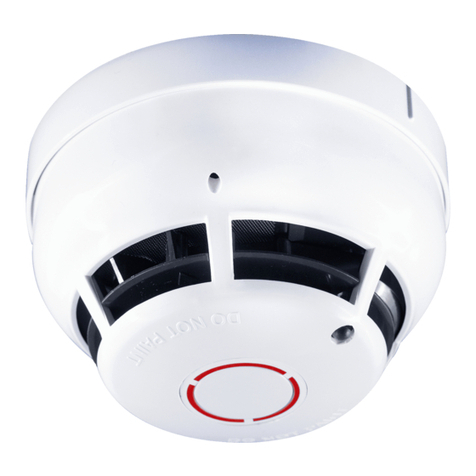
The 6000PLUS detector range has a break off bridging piece shown in diagram one. Removing the small plastic bridging piece
will enable the locking mechanism, and when the detector is fitted on a base, it will lock the detector. See diagram 1.
Bridging piece
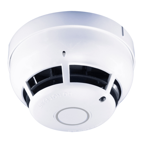
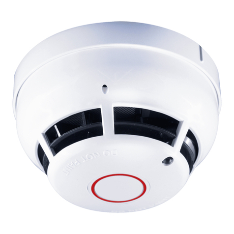
Diagram1 - Locking bridging piece and cross head screw position Diagram 2 - Outer case removed exposing optical chamber
6000PLUS/HT/TSL Service and Maintenance details
•Remove Detector from its base, check panel for Zone fault.
•Remove two cross head screws shown in diagram 1.
•Remove detector outer case. Note the position of thermistor, and remove mouldings with care so as not to damage
thermistor.
•Remove Deflector and top chamber moulding, keeping mesh in place on top chamber. Ensure light pipe does not get lost,
and be careful of the piezo and beacon connecting wires.
•Clean all mouldings and mesh with a soft brush, clean inside the bottom chamber with soft brush (see Diagram 2).
•Clean thermistor and deflector with soft brush
•Clean detector outer case with a cloth.
•To rebuild, first fit deflector to top chamber noting arrow position to centre of optical chamber. Ensure mesh is flat to top
chamber moulding. Ensure Light pipe is in place.
•Fit top chamber/deflector assembly to bottom chamber. Note: Be aware, small bead thermistor should be carefully inserted
through central hole.
•Once top chamber/deflector is in place ensure thermistor is vertical and straight. The thermistor bead should be vertical,
see diagram 3.
•Fit detector outer case, using light pipe as orientation guide.
•Fit the two cross head fixing screws, tighten sufficiently to compress mouldings, but be aware over tightening may strip the
thread on the outer case. Visually inspect to ensure thermistor is visible in correct position.
•Fit back onto base.
•Once detector logged back onto panel, wait for confirmation LED flash, then apply heat to the detector ensuring activation
of control panel. Confirm A/D value of thermal channel is correct. Apply heat if setting on control panel allows activation.
•Test the operation of the integral sounder and beacon.
•Remove old service label and fit new label to detector.
Diagram 3 - Re Assembly showing correct thermistor position
Cross head
screws
