Pro-tec 6000 PLUS Guide

DEL2104 Issue 4 02/11 SB Page 1 of 3 Copyright © Protec Fire Detection plc 2010
6000PLUS/OPHTCO/S Installation, Commissioning and Service Instructions
Overview
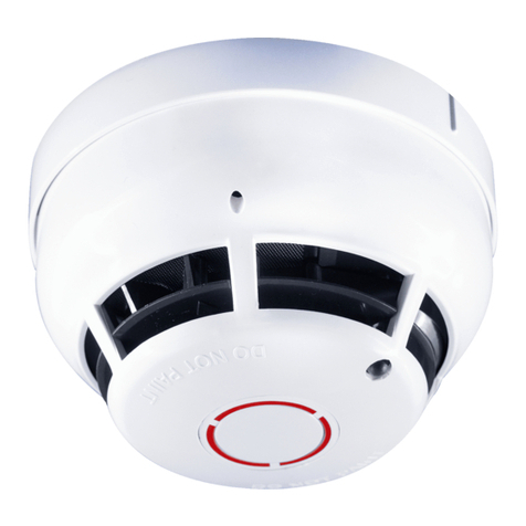
The Protec 6000PLUS/OPHTCO/S is a loop powered Fire sensor which reports Smoke, Thermal and Carbon Monoxide levels
in its installed location to the fire alarm control panel. The sensor is also equipped with an integrated loop powered sounder.
Technical Specification
Loop protocol Protec Algo-tec™ 6000PLUS
Loop isolator fitted Yes
Loop voltage range 18 to 27V Algo-tec™ loop
Loop average quiescent current (24V loop) 0.45 mA
Loop average alarm current (24V loop ) 5mA
Analogue values
Smoke Thermal Carbon Monoxide
Normal 40 to 60 bits
Fault Low <35 bits
Fault low High>90 bits
Normal 80 to 180 bits
Fault Low <25 bits
Fault High>250 bits
Normal 30 to 100 bits
Fault Low <20 bits
Fault High>150 bits
Indications On-board red indicating LED
Environmental operational limits -10 to 50 degrees C ( 95% RH no condensation or icing )
Sounder Frequencies Continuous 990Hz, Warble 730Hz to 990Hz, Pip 990Hz
Sounder synchronisation Sounder synchronisation is achieved by panel control
IP rating IP21C
Isolator Specification Please see Protec DEL2110 for details
Installation
1. Base options: 6000PLUS/BASE LPCB Approved as part of product approval
6000PLUS/FFBASE LPCB Approved as part of product approval
28-075-01 (Plug and Play Fast Fix) LPCB Approved as part of product approval
28-075-02 (Plug and Play Surface) LPCB Approved as part of product approval
Note: See individual information sheets for base wiring details.
2. Install the detector in the base, turn firmly clockwise.
Commissioning
1. Each 6000PLUS/ detector has a unique serial number which will be used as part of the commissioning of the fire alarm
system. It is necessary to remove one of the ‘peelable’ bar code labels present on the product and place it in the
commissioning booklet supplied with each Protec addressable control panel. The bar code sticker should be placed at the
relevant loop and address position intended. It is important that serial numbers are not mixed otherwise the addressing of
the 6000PLUS/OPHTCO/S will be incorrect when commissioned.
2. Commission the device onto the system as detailed in the installation and commissioning manual for the fire alarm panel
being used.
6000PLUS/OPHTCO/S Certification Details
EN Standards Compliance/ Approvals table
0 8 3 2
Protec Fire Detection plc, Nelson, Lancashire, England, BB9 6RT
10
0832-CPD-1177
EN 54 - 5
Point type heat detector
Class A2
6000PLUS/OPHTCO/S
EN 54 - 7
Point type smoke detector
6000PLUS/OPHTCO/S
EN 54 - 3: 2001 + A1 + A2
Alarm devices – Sounder
Type A: For indoor use
6000PLUS/OPHTCO/S
EN 54 - 17:2005
Short-circuit isolator
6000PLUS/OPHTCO/S
Technical Data included in this datasheet DEL2104 Issue 4
High Sensitivity Med Sensitivity Low Sensitivity Isolator/sounder
No Approval Approved to:
EN 54-7: 2000 + A1: 2002 + A2: 2006
EN 54-5: 2000 + A1: 2002, Class A2
CEA 4021:2003-07
Approved to:
EN 54-7: 2000 + A1: 2002 + A2: 2006
EN 54-5: 2000 + A1: 2002, Class A2
CEA 4021:2003-07
Approved to:
EN 54-17: 2005
EN 54-3: 2001 + A1: 2002 + A2:
2006

DEL2104 Issue 4 02/11 SB Page 2 of 3 Copyright © Protec Fire Detection plc 2010
6000PLUS/OPHTCO/S Installation, Commissioning and Service Instructions
6000PLUS Locking Mechanism
The 6000PLUS detector range has a break off locking tab shown in diagram one. Removing the small plastic cross bar will
enable the locking mechanism, and when the detector is fitted on a base, it will lock the detector. See diagram 1.
Bridging piece
Diagram1 - Locking bridging piece and cross head screw position Diagram 2 - Outer case removed exposing optical chamber
6000PLUS/OPHTCO/S Service and Maintenance details
•Remove Detector from its base, check panel for Zone fault.
•Remove two cross head screws shown in diagram 1.
•Remove detector outer case. Note the position of thermistor, and remove mouldings with care so as not to damage
thermistor.
•Remove Deflector and top chamber moulding, keeping mesh in place on top chamber. Ensure light pipe does not get lost,
and be careful of sounder connection.
•Clean all mouldings and mesh with a soft brush, clean inside the bottom chamber with soft brush (see Diagram 2).
•Clean thermistor and deflector with soft brush
•Clean detector outer case with a cloth.
•To rebuild, first fit deflector to top chamber noting arrow position to centre of optical chamber. Ensure mesh is flat to top
chamber moulding. Ensure Light pipe is in place.
•Ensure both lenses are in place on bottom chamber moulding.
•Fit top chamber/deflector assembly to bottom chamber, placing assembly over CO cell. Note: Be aware, small bead
thermistor should be carefully inserted through central hole.
•Once top chamber/deflector is in place ensure thermistor is vertical and straight. The thermistor bead should be vertical,
see diagram 3.
•Fit detector outer case, using light pipe as orientation guide.
•Fit the two cross head fixing screws, tighten sufficiently to compress mouldings, but be aware over tightening may strip the
thread on the outer case. Visually inspect to ensure thermistor is visible in correct position.
•Fit back onto base.
•Once detector logged back onto panel, wait for confirmation LED flash, then apply smoke and CO to the detector in turn
ensuring activation of control panel. Confirm A/D value of thermal channel is correct. Apply heat if setting on control panel
allows activation.
•Check the operation of the integrated sounder
•Remove old service label and fit new label to detector.
•The maximum life expectancy of the CO element of the OPHTCO detector is seven years; we recommend that the detector
is completely replaced when reaching this age or when the detector fails to operate during system maintenance, whichever
comes first. The date of manufacture is printed on the back of each detector.
Diagram 3 Re Assembly showing correct thermistor position
Thermistor position
Deflector moulding
Cross head
screws
Remove Top
Chamber and clean
mesh and plastic
Bottom
chamber
Clean in here
using soft
brush

DEL2104 Issue 4 02/11 SB Page 3 of 3 Copyright © Protec Fire Detection plc 2010
6000PLUS/OPHTCO/S Installation, Commissioning and Service Instructions
Polar outputs and profiles (sounder)
This manual suits for next models
2
Table of contents
Other Pro-tec Accessories manuals
