Compur Monitors Statox 506 User manual

Statox 506 Sensor Head
Operations Manual

2
Statox 506 Sensor Head
Operations Manual
Page
1SAFETY INSTRUCTIONS 3
2STATOX 506 CONSTRUCTION 4
3INSTALLATION AND CONNECTION 5
3.1 Installation 5
3.2 Electrical Connection 6
3.2.1 Statox 506 cable connection 7
3.2.2 Connection diagram with Statox 502/503 Control Module in the 2-wire mode 9
3.2.3 Connection diagram with Statox 502/503 Control Module in the 3-wire mode 10
4CONTROL ELEMENTS AND DISPLAY 11
5START UP 11
6MENU 13
6.1 Main Menu 13
6.2 Setting the Real Time Clock 15
6.3 Current Output in the Service Mode 16
6.4 Sensor Calibration 17
6.5 Prooftest 19
6.6 Info Menu 20
6.7 Test Menu 22
7SENSOR REPLACEMENT 22
8MAINTENANCE AND CLEANING 24
9ACCESSORIES AND SPARE PARTS 24
10 STATUS- AND ERROR MESSAGES 25
10.1 Status Messages 25
10.2 Error Messages 27
11 FUNCTIONAL SAFETY 28
11.1 Safety Function 28
11.2 Diagnostic Time and Measuring Cycle 28
11.3 Installation and Parameter Settings 28
11.4 Maintenance Schedule 28
11.5 Repair and Spare Parts 28
11.6 Failure Rates and Safe Failure Fraction 29
11.7 Average Probability of Failure on Demand 29
11.8 Classification of the Safety Integrity Level (SIL) 29
11.9 Lifetime 29
12 TECHNICAL DATA 30
12.1 Transmitter General 30
12.2 Sensor Data 30
13 EU-DECLARATION OF CONFORMITY 33

3
1 Safety Instructions
Statox 506 is a transmitter designed as an intrinsically safe device, group 2 category II. It measures the
concentration of toxic gases and oxygen in ambient air. It is safe to be operated in classified areas zone 1
and zone 2.
The gas specific parameters are stored in an F–Ram on board of the sensor. These will be downloaded
into the sensor head electronics automatically as soon as the sensor is plugged in.
Safety advice:
Read and observe this manual carefully. Keep it in a safe place.
This transmitter must be installed and connected observing the regulations for operation in hazardous
areas. It must be performed by authorized and trained personnel only. Respect the regulations for the
operation of safety instrumented systems including standard DIN EN 60079-14.
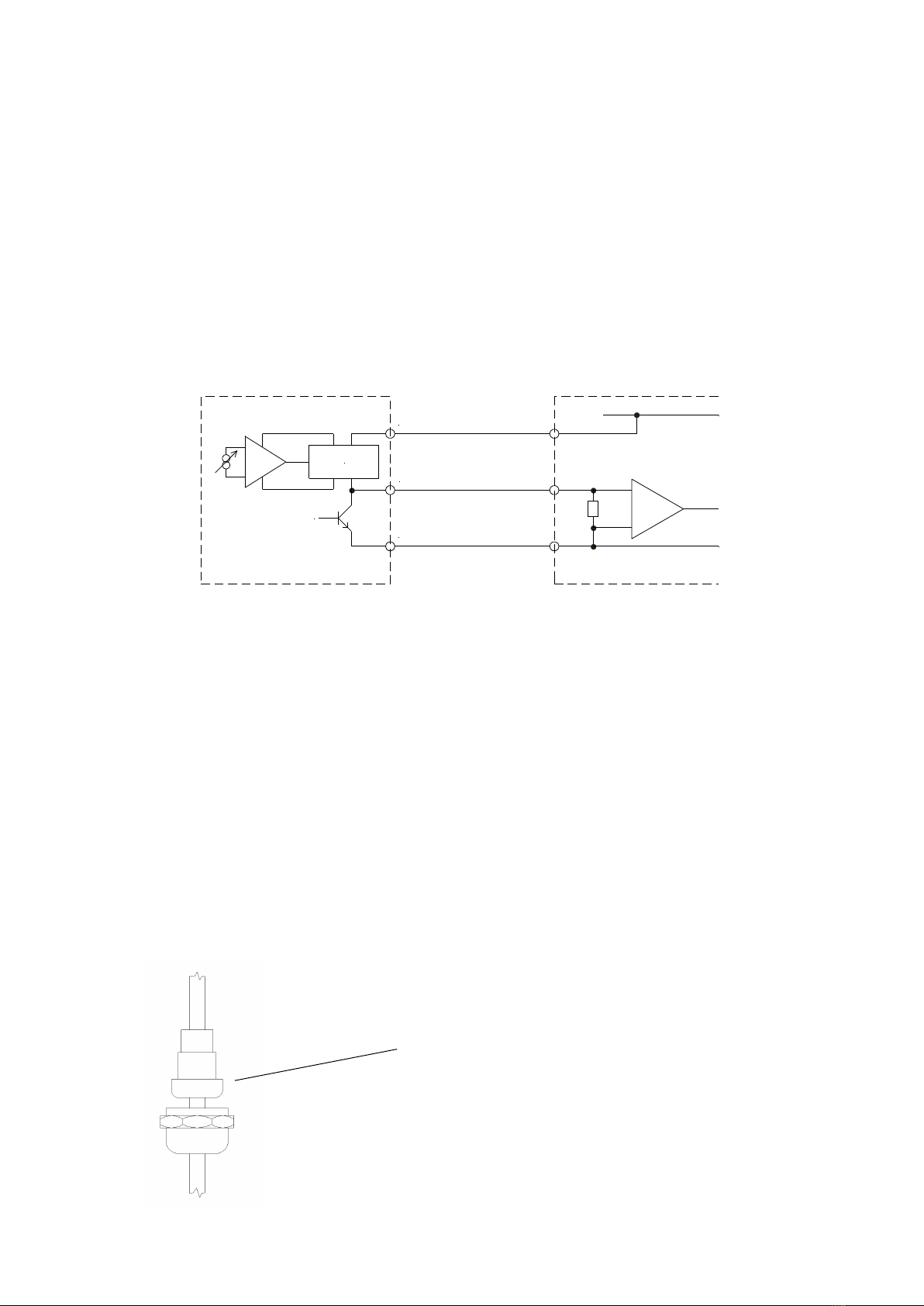
If operated in a hazardous area, the sensor head power supply must run through an intrinsically safe
repeater or the loop itself must be intrinsically safe, see chapter 3.2 Electrical Connection.
Potential equalization must be in place along the intrinsically safe circuit.
Statox 506 must not be operated in an ambience outside the technical specifications, see chapter 12.
Statox 506 must be operated and serviced by authorized and trained personnel only. Use only original
Compur parts as spares and consumables.
Do not operate uncomplete or damaged sensor heads.
All of the above warnings must be observed. Incorrect installation or connection will void the
explosion proof rating and thus be dangerous to human life and assets.

4
2 Statox 506 Construction
1 Aluminium housing
2 Display
3 Ground contact
4 Cable gland
5 Sensor cover
6 Dust filter (comes with the sensor)
7 Filter holder
8 Sensor (not part of the sensor head)
9 Sensor socket
10 Housing screws
11 Keyboard
12 Magnetic pin
1
11
2
10
6
3
9
4
8
5
7
12

5
3 Installation and Connection
3.1 Installation
Drilling plan and dimensions Statox 506
Statox 506 should be installed close to a potentially dangerous location or in between a dangerous
location and a workplace. Some parameters may have an impact on the measurement:
Air flow (wind, ventilation, thermal impact)
Specific gas properties such as density
Protection from direct sunlight, splash water, dirt etc.
Take care for good accessibility for maintenance and repair.
Loosen the 4 captive screws. Put the cover on a clean place. In order to ease installation, the flat cable is
not connected ex works.
Fasten the housing to the wall.
Screw specs: Ø ≤4.5 mm, head Ø ≤6.9 mm.
Install in an upright position with the sensor downwards!
Avoid ingress of dust or humidity.
Connect the cable as shown in chapter 3.2.
Connect the cover to the pcb with the flat cable. The plug is
mechanically coded.
Fasten the cover.

6
Connect the ground contact to ground. It can take cables up to 4 mm². Reassure proper grounding.
Use the optional pipe kit (see chapter 9) to install the sensor head to horizontal or vertical pipes.
3.2 Electrical Connection
If installed in a classified area, the power supply must run through an intrinsically safe repeater.
The combination Sensor head / repeater / cable must be within these parameters:
Specifications:
Uo, Io, Co, Lo :Approved repeater specifications.
Ui, Ii, Ci, Li: Approved sensor head specifications (Technical data)
CL = Cable capacity in nF/km
LL = Cable inductivity in nH/m
l = Cable length in m
The allowable cable length must be calculated from the cable capacity and the inductivity of the sensor
head with this formula:
lmax = (Co- Ci) / CL
Recommended cable:
2 x or 3 x 0.5 mm², preferably shielded (e.g. LiYCY).
Terminals: 0.25 –2.5 mm² (AWG 24 - 12).
The cable gland can accept cables from 4 to 12 mm outer diameter.
Uo ≤Ui
Io ≤Ii
Co≥ Ci+ l .CL
Lo ≥ Li+ l .LL
Example:
Cable type LiYCY 0,75mm² : CL = 150 nF/km
Repeater: Co = 705 nF
Sensor head: Ci = 24 nF
lmax = 4540 m

7
Advantage of 3 wire operation:
The signal in the error mode must always be 2 mA when operating in 2 wire installation in order to assure
enough power for the operation.
If you install the sensor head with a 3 wire cable, you can set the current in the error mode to 0 mA. Then
you can set the current in the service mode to 2 mA and thus differentiate between system failure (critical
error) and service mode (non - critical error). This is essential if you operate the Statox 506 as a safety
operated system (SIS). See also chapter 6.3!
If you operate the Statox 506 sensor head with a Statox 502 or 503 Control Module, use the schematics
as shown in chapter 3.2.2 or 3.2.3.
If you operate the Statox 506 sensor head directly on a PCS, use the following diagram.
In case of 2 wire operation use terminal 1 and 2.
V+
0V
2-22mA
I=0mA
1
2
3
Caution:
First complete the electrical connections, then plug the sensor in.
3.2.1 Statox 506 cable connection
Cable specifications see above.
Make sure the sensor is not plugged in!
Sensor
Statox 506
PCS
Remove the nut, the washer set and the metal spring
from the cable gland.
Push the nut and the washer set over the cable end.
The washers have lips which can be removed in order
to widen the inner diameter.

8
+ - 0
10-15 mm
6 mm
50 mm
Strip the cable end as shown here.
Push the cable shield backwards and shorten it to
10-15 mm.
Push the metal spring onto the cable until it makes
good contact with the shield.
Push the cable into the cable gland to the end stop
of the metal spring.
Fasten the nut slightly.
The cable isolation end shall match with the inner
end of the cable gland. (Arrow)
Now fasten the nut.
The package includes a ferrite core which will help
to avoid electromagnetic interferences. Push it over
the connection cable before connecting it.
Connect the wires to the terminal plug. This plug
can be removed, in order to ease installation.
Terminal 3 must only be connected for 3 - wire
operation. Then re–plug the terminal plug.
Connect the ground terminal to the ground of the
building. In order to avoid ground loops only ground
this end of the cable! If installed in a classified area,
an equal potential all along the intrinsically safe
circuit is required.
As soon as power is on, the sensor head performs
a self–test and then displays its operating program
index.
See chapter 5: Start up.

9
3.2.2 Connection diagram with Statox 502/503 Control Module in the 2-wire mode
Before connecting the Statox 506 to a Compur Statox 502 or Statox 503 Control Module, the appropriate
program in the control module must be set. The programs are listed in the operation manual of the control
module.
3.2.2.1 2-wire mode installation in non-hazardous areas
3.2.2.2 2-wire mode installation in hazardous areas
Caution:
The input / output terminals may be different for
different intrinsically safe repeaters. Wrong
connection might destroy the repeater and / or the
control module. Avoid short–circuits and wrong
polarity!
The terminal numbers at the repeater refer to
model 9160/13-11-11 from R.Stahl, Waldenburg
(Siemens 7NG4124-0AA00). It needs an own
power supply and operates as current source at
terminals 1 and 2.
Do not operate control module and repeater on
the same bus –the polarity is different!
Non-hazardous area
Hazardous area
Power
supply
Power
supply

10
3.2.3 Connection diagram with Statox 502/503 Control Module in the 3-wire mode
Before connecting the Statox 506 to a Compur Statox 502 or Statox 503 Control Module, the appropriate
program in the control module must be set. The programs are listed in the operation manual of the control
module.
3.2.3.1 3-wire mode installation in non-hazardous areas
3.2.3.2 3-wire mode installation in hazardous areas
Caution:
The input / output terminals may be different for
different intrinsically safe repeaters. Wrong
connection might destroy the repeater and / or the
control module. Avoid short–circuits and wrong
polarity!
The terminal numbers at the repeater refer to
model 9160/13-11-11 from R.Stahl, Waldenburg
(Siemens 7NG4124-0AA00). It needs an own
power supply and operates as current source at
terminals 1 and 2.
Do not operate control module and repeater at
the same bus –the polarity is different!
Non-hazardous area
Hazardous area
Power
supply
Power
supply

11
4 Control Elements and Display
The display is an 8 digit 14-segment-LCD.
You can program the sensor head by holding the magnetic pin on the control buttons:
Symbol
Name
Function
Right
Increase value.
Navigate to the right.
Push and hold the contact for speed mode.
Left
Decrease value.
Navigate to the left.
Push and hold the contact for speed mode.
Reset
Navigate backwards.
Change entry.
Enter
Main menu.
Confirm.
5 Start up
After connecting the sensor head to power, it performs a self–test and after a few seconds displays
the software index.
Remove the yellow protection cap from the sensor cover.
Install the sensor and the dust filter which is included in the sensor package. Find more details in
chapter 7.
After the sensor has been plugged in, the sensor head reads the sensor parameters and displays the
parameter set index, the target gas, the measuring range and the best-before date of the sensor in the
format week / year. After zero has stabilized, the sensor head goes into the measuring mode.
If you plug in another sensor type as before, the display shows NEW TYPE. Confirm this with ENTER.
Otherwise remove the sensor and plug in the right type.
As long as the sensor head has not gone into the measuring mode, it is in the ERROR mode.
(0 mA signal in 3–wire operation, 2 mA in 2–wire operation)
Once the sensor head has started the measuring mode you can program the real time clock (chapter
6.2) and the service mode setting (chapter 6.3).
Some sensors do require a certain warm–up time until zero has stabilized. If sensor and sensor head
have different temperatures, allow enough time to equalize. 1 hour after installation a zero adjustment
should be done (chapter 6.4).

12

13
6 Menu
6.1 Main Menu
Push the ENTER –button in order to enter the main menu. Use the left / right –buttons to enter the
password “94”. This password cannot be changed.
You can navigate in the main menu in either direction. Enter a sub menu by pushing the ENTER –button.
RESET brings you step by step back into the measuring mode.
After you have entered the password, the sensor head is now in the service mode. The output is set to 2
or 4 mA. The measured value will not be transmitted.
If you do not operate a button for more than 5 minutes, the sensor head will return automatically into the
measuring mode. Exceptions to this are listed in the relevant sub menus.

14
see 6.4
Dial Code 94.
If you enter a wrong
code, the sensor head
will return to the
measuring mode.
Now you are in the
service mode.
see 6.2
see 6.3
see 6.6
see 7
see 6.7
see 6.5

15
6.2 Setting the Real Time Clock
The real time clock has been set ex-works. Probably you will have to adjust it to your local time. Only
correct clock settings make sure that all alarm and calibration protocols are correct.
The clock is buffered with a battery.
All flashing display segments shown below in bold face are adjustable. Confirm with ENTER.
Time (hour / minute) is displayed in the 24 hour format.
Date is displayed in the format day / month / year.

16
6.3 Current Output in the Service Mode
The analog output can be set to 2 or 4 mA in the service mode. Here is a listing of all possible modes:
Error
(critical error)
Service
(non critical error)
Display at the Statox 503
Control Module
2-wire operation
2 mA
2 mA
4 mA
Service Mode
„0“
3-wire operation
0 mA
2 mA
4 mA
Error 2
Service Mode
„0“
Caution: In the menu REPLACE the sensor head will always remain in the service mode, even if there is
no sensor plugged in.
If you operate the sensor head as a SIL - device EN 61508 (functional safety), the analog output must
be programmed to 2 mA in the service mode!
As soon as programmed, the output is active.

17
6.4 Sensor Calibration
Sensor and sensor head must have the same temperature!
For calibration you need the Statox 505/506 calibration adapter art # 570505, and an inert gas tube
4x1 mm (i.e. art. # 556710) and span gas (allowable concentration see chapter 12.2). If you are not
sure that the ambient air is clean, you need synthetic air for zero adjustment.
In case the calibration fails for whatever reason, the sensor head will continue to operate with the
existing parameters, but the display will alternate showing the measured value and ZERO ADJ
respectively CALIB until a calibration procedure has been completed.
O2 sensors do not require a zero adjustment, as their output in pure nitrogen is nearly zero. If you are
not sure that the ambient air is clean and does have 20.9 % oxygen content, you should use synthetic
air for the adjustment. Apply the synthetic air as soon as the CALIB menu has started.
During calibration, the timeout is not active. The automatic return into the measuring mode is disabled!
Calibration procedure:
Enter the CALIB menu and start the zero adjustment. As soon as „000“ is no longer flashing, zero has
been adjusted successfully.
Push the calibration adapter onto the sensor. Connect the span gas cylinder.
Start the gas calibration with ENTER.
As soon as GAS ON appears on the display, turn the gas on. Required flow is ca. 20 l/h (300 ml/min).
If you have to follow a zero emission policy, you can connect an active carbon filter at the adapter
outlet. Take care to avoid a stagnation pressure! The sensor head will detect the gas and confirm with:
GAS.IS.ON.
As soon as the measured value has stabilized, CONCENT? will appear in the display. Confirm with
ENTER and enter the concentration of the span gas you are using in ppm (for O2in %Vol). Use the
LEFT / RIGHT arrows to do this. Confirm with ENTER.
The sensor head will confirm a successful calibration with DONE. Push ENTER. Now the display
shows the actual detected concentration flashing. Check the reading.
Remove the calibration adapter and shut the gas off. Let the reading decrease to zero, then push
ENTER in order to enter the measuring mode. If you do nothing, the timeout feature will activate the
measuring mode after 5 min.
In the graph below potential errors are shown in dotted letters. You can find a complete error list in
chapter 10.2!
Filter
Gas
Calibration
adapter

18
Statox 506 Calibration procedure

19
6.5 Prooftest
The Prooftest checks the proper function of sensor and sensor head on a regular schedule. It cannot
be used to test the entire alarm chain, because the analog signal is set to 2 or 4 mA. If you want to
prooftest the entire alarm chain, this must be done in the measuring mode. You do have the capability
to test connected devices in the TEST menu (see chapter 6.7).
You need Statox 505/506 calibration adapter art. #. 570505, an inert gas tube 4x1 mm (i.e. art. #.
556710) and span gas with a concentration within the measuring range, preferably close to the alarm
threshold.
Connect the gas adapter with a slight turn clockwise. Connect the gas tube (picture chapter 6.4).
Required flow is ca. 20 l/h (300 ml/min).
If you have to follow a zero emission policy, you can connect an active carbon filter at the adapter
outlet. Take care to avoid stagnation pressure to build up.
When the sensor head displays PROOF, confirm with ENTER and turn the gas on. The measured
value will be flashing constantly. Wait until the signal is stable before reading the measured value.
Remove the gas adapter and shut the gas off. Let the reading decrease to zero, then return to the
measuring mode.
If the measured value deviates too much, you should perform a calibration (see chapter 6.4). In many
areas legislation allows ± 20%. Follow your local regulations.
Special timeout: 30 minutes instead of 5 min.

20
6.6 Info Menu
Sub menu ALARM
An alarm protocol starts as soon as the internal alarm threshold is exceeded. This threshold is sensor
specific. Find a listing in capter 12.2.
The memory can store only 3 alarm events. These parameters are stored: alarm start, concentration
maximum, alarm end. The alarm events are not listed chronologically. If there was no alarm yet, the
display shows zeros only.
In order to achieve a meaningful protocol, the clock must be set correctly (see chapter 6.2).
Sub menu DOSIS
The total exposure is the product of concentration multiplied by exposure time ppm * h. Exposure by
calibration is neglected.
The maximum exposure reading depends on the measuring range. It is either 9.99 or 99.9 or 999
ppm * h. If it is too high to be displayed, the display shows FF PPMH.
Oxygen sensors do not have this feature.
The total exposure provides information about the exposure history of the sensor, but it is not a direct
quality criterion.
Sub menu SENSOR
FJ is an internal factor, created during calibration. You cannot use this to calculate the sensor signal.
JUSTDATE is the most recent calibration date.
SN is the sensor serial number.
BB is the best before date of the sensor in week / year.
Table of contents
Other Compur Monitors Accessories manuals