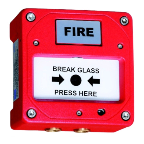
Pro-tec 4400 User manual

93-310-10 Issue 4 Rev5 Page 1 of 88 Copyright Protec Fire DetectionPLC
6400 OPERATINGMANUAL
I
IS
SS
SU
UE
ES
S
ISSUE DATE RELEASED DETAILS OF CHANGE AUTHOR
4Rev2 September 2004 Changes for 4000 series. DB
4Rev3 April 2005 Screenshots updatedandother minor changes K.Z.
4Rev4 September 2006
Updatedsection4.1(AdvancedOptions)
Updatedsection6.1(Fire AlarmCount)
Updatedsection8.2(DSZ&DSG status)
Updatedsection10.1(View/ Edit)
Updatedsection13.3(Low&high sensitivity)
Addedsection26 (Loop LCD Panel)
Several screenshots updated
PD
4Rev5 April 2007
Removedsection1.5
Addedsection8.5.2(Fault Link)
Changed‘Device Disabled’ ledto‘Disablement’
Addedsection8.7(Output DelayDisablement)
Several screenshots updated
PD
Notes
1) This manual covers 4400, 5400 and 6400 systems. The differences are described in the
appropriate sections.
2) This manual covers Fire and General Alarm systems. The differences are described in the
appropriate sections.

93-310-10 Issue 4 Rev5 Page 2 of 88 Copyright Protec Fire DetectionPLC
6400 OPERATINGMANUAL
C
CO
ON
NT
TE
EN
NT
TS
S
O
OV
VE
ER
RV
VI
IE
EW
W....................................................................................................................................................................5
1.16400 NETWORK OVERVIEW.......................................................................................................................... 5
1.26400 NODE DESCRIPTIONS............................................................................................................................ 6
1.3DCN NODE ........................................................................................................................................................ 6
1.4LPN NODE ......................................................................................................................................................... 6
D
DC
CN
N
F
FU
UN
NC
CT
TI
IO
ON
NS
S ......................................................................................................................................................... 7
2.1NORMAL DISPLAY..........................................................................................................................................7
2.2VIEWING FIRE / ALARM EVENTS ..............................................................................................................8
2.2.1MULTIPLE DEVICES IN ALARM ............................................................................................................9
2.2.2GENERAL ALARM ....................................................................................................................................9
2.3 PRINTING FIRE EVENTS......................................................................................................................... 10
2.4 SILENCING FIRE EVENTS ...................................................................................................................... 10
2.5SOUND ALARMS............................................................................................................................................11
2.6RESETTING FIRE EVENTS ......................................................................................................................... 11
2.7DISPLAY OF FAULTEVENTS...................................................................................................................11
2.7.1VIEWING FAULTEVENTDETAILS. .................................................................................................12
2.7.2MUTING THE ‘FAULT’BUZZER...........................................................................................................12
2.8DISPLAY OF DISABLEMENTS...................................................................................................................13
2.8.1VIEWING DISABLEMENTDETAILS..................................................................................................14
2.8.2MUTING THE ‘DISABLEMENT’BUZZER ........................................................................................14
R
RO
OU
UT
TI
IN
NE
E
A
AT
TT
TE
EN
NT
TI
IO
ON
N..............................................................................................................................................15
3.1RESPONSIBLE USER.......................................................................................................................................15
3.2ROUTINE TESTS..............................................................................................................................................15
U
US
SE
ER
R
M
ME
EN
NU
U
A
AC
CC
CE
ES
SS
S................................................................................................................................................16
4.1MENU ACCESS ...............................................................................................................................................16
S
SE
ET
T
T
TI
IM
ME
E
&
&
D
DA
AT
TE
E.....................................................................................................................................................18
5.1SETTIME &DATE. ........................................................................................................................................18
5.2SETTING THE DATE......................................................................................................................................19
5.3SETTING THE TIME.......................................................................................................................................21
D
DI
IS
SP
PL
LA
AY
Y
E
EV
VE
EN
NT
TS
S......................................................................................................................................................22
6.1DISPLAY EVENTS.........................................................................................................................................22
6.2DISPLAY PASTFIRES..................................................................................................................................23
6.3DISPLAY PASTFAULTS.............................................................................................................................. 24
P
PR
RI
IN
NT
TE
ER
R
M
ME
EN
NU
U.......................................................................................................................................................... 25
7.1PRINTER MENU.............................................................................................................................................25
7.2PRINTCURRENTFAULTS.......................................................................................................................... 26
7.3PRINTCURRENTDISABLEMENTS...........................................................................................................27
7.4PRINTPASTEVENTS ..................................................................................................................................28
7.4.1PRINTPASTFIRES / ALARMS ............................................................................................................29
7.4.2PRINTPASTFAULTS............................................................................................................................ 29
7.4.3PRINTPASTDISABLEMENTS ............................................................................................................30
7.4.4PRINTPASTOTHER EVENTS............................................................................................................30
7.5PRINTANALOGUE VALUES......................................................................................................................31
7.6PRINTADDRESS S/N .....................................................................................................................................32
7.7PRINTHIGH ANALOGUE VALUES...........................................................................................................33
7.8CANCELPRINTING.......................................................................................................................................33
D
DI
IS
SA
AB
BL
LE
EM
ME
EN
NT
T
M
ME
EN
NU
U..............................................................................................................................................34
8.1DISABLEMENTMENU .................................................................................................................................34
8.2DEVICE DISABLE / NORMALISE................................................................................................................35
8.3DISABLEMENTS TO VIEW ......................................................................................................................... 39
8.4ZONE DISABLE / NORMALISE.....................................................................................................................41
8.5OUTPUTDISABLEMENTMENU ................................................................................................................43

93-310-10 Issue 4 Rev5 Page 3 of 88 Copyright Protec Fire DetectionPLC
6400 OPERATINGMANUAL
8.5.1DISABLE / ENABLE FIRE LINK ........................................................................................................ 43
8.5.2DISABLE / ENABLE FAULTLINK .................................................................................................... 44
8.5.3DISABLE / ENABLE ALARM OUTPUTS.............................................................................................. 45
8.5.4DISABLE / ENABLE CONTROLOUTPUTS.......................................................................................... 46
8.6CHANGE TO ADDRESS DISABLE .............................................................................................................. 47
8.7OUTPUTDELAY DISABLEMENT ............................................................................................................... 48
T
TE
ES
ST
T
O
OP
PT
TI
IO
ON
NS
S........................................................................................................................................................... 50
9.1TESTOPTIONS............................................................................................................................................... 50
9.2LAMPTEST.................................................................................................................................................... 50
9.3VIEWANALOGUE VALUES....................................................................................................................... 51
9.4WALK TESTMENU ...................................................................................................................................... 53
9.4.1WALK TESTZONE................................................................................................................................... 54
9.5RVAV (Remote Visual Address Verification) .................................................................................................. 56
9.5.1RVAV SINGLE ......................................................................................................................................... 56
9.5.2RVAV DESCRIPTION.............................................................................................................................. 58
T
TE
EX
XT
T
E
ED
DI
IT
TO
OR
R............................................................................................................................................................. 59
10.1TEXTEDITOR.............................................................................................................................................. 59
10.2EDITLOOPDEVICE TEXT ......................................................................................................................... 60
C
CL
LE
EA
AR
R
S
SY
YS
ST
TE
EM
M
F
FA
AU
UL
LT
T........................................................................................................................................... 63
11.1CLEAR SYSTEM FAULT .......................................................................................................................... 63
A
AD
DV
VA
AN
NC
CE
ED
D
O
OP
PT
TI
IO
ON
NS
S............................................................................................................................................... 64
12.1ADVANCED OPTIONS................................................................................................................................. 64
12.2EXCHANGE DEVICES................................................................................................................................. 65
12.3ACCESS CODES........................................................................................................................................... 70
R
RE
EF
FE
ER
RE
EN
NC
CE
E................................................................................................................................................................ 72
13.1THRESHOLD LEVELS FOR 6000 SERIES ANALOGUE DEVICES.......................................................... 72
13.2THRESHOLD LEVELS FOR 6000 SERIES DIGITAL DEVICES................................................................ 72
13.3THRESHOLD LEVELS FOR 5000 SERIES DEVICES.................................................................................. 73
13.4THRESHOLD LEVELS FOR 4000 SERIES DEVICES.................................................................................. 73
13.5OPERATING MENU FLOWCHART.............................................................................................................. 74
N
NE
ET
TW
WO
OR
RK
K
R
RE
EP
PE
EA
AT
T
P
PA
AN
NE
EL
LS
S................................................................................................................................... 75
14.1NETWORK LCD PANEL-(Nonetworkcontrols)........................................................................................ 75
14.2RDN PANEL–(Withnetworkcontrols) ........................................................................................................ 75
N
NE
ET
TW
WO
OR
RK
K
L
LC
CD
D
D
DI
IS
SP
PL
LA
AY
Y........................................................................................................................................ 76
15.1NETWORK LCD DISPLAY.......................................................................................................................... 76
F
FU
UN
NC
CT
TI
IO
ON
N
B
BU
UT
TT
TO
ON
NS
S............................................................................................................................................... 77
16.1-FUNCTION BUTTONS................................................................................................................................ 77
M
ME
EN
NU
U
O
OP
PT
TI
IO
ON
NS
S......................................................................................................................................................... 78
17.1MENU OPTIONS........................................................................................................................................... 78
17.2MENU VIEWING INSTRUCTIONS............................................................................................................. 78
V
VI
IE
EW
WI
IN
NG
G
F
FI
IR
RE
E
E
EV
VE
EN
NT
TS
S........................................................................................................................................... 79
18.1VIEWING FIRES / ALARMS........................................................................................................................ 79
18.2VIEWING MULTIPLE FIRE / ALARMS ................................................................................................... 79
S
SI
IL
LE
EN
NC
CI
IN
NG
G
F
FI
IR
RE
E
E
EV
VE
EN
NT
TS
S........................................................................................................................................ 81
19.1SILENCING FIRE EVENTS.......................................................................................................................... 81
R
RE
ES
SE
ET
TT
TI
IN
NG
G
A
A
F
FI
IR
RE
E
E
EV
VE
EN
NT
T..................................................................................................................................... 82
20.1RESETTING AFIRE EVENT ....................................................................................................................... 82
V
VI
IE
EW
W
C
CU
UR
RR
RE
EN
NT
T
F
FA
AU
UL
LT
TS
S......................................................................................................................................... 83
21.1VIEWCURRENTFAULTS........................................................................................................................... 83
V
VI
IE
EW
W
C
CU
UR
RR
RE
EN
NT
T
D
DI
IS
SA
AB
BL
LE
EM
ME
EN
NT
TS
S......................................................................................................................... 84
22.1VIEWCURRENTDISABLEMENTS ........................................................................................................... 84
P
PR
RI
IN
NT
TI
IN
NG
G.................................................................................................................................................................... 85
23.1PRINTING -RDN Only ................................................................................................................................ 85
L
LA
AM
MP
PT
TE
ES
ST
T.................................................................................................................................................................. 86
24.1LAMPTEST.................................................................................................................................................... 86
A
AB
BO
OR
RT
T
P
PR
RI
IN
NT
TO
OU
UT
T.................................................................................................................................................... 86
25.1ABORTPRINTOUT ...................................................................................................................................... 86

93-310-10 Issue 4 Rev5 Page 4 of 88 Copyright Protec Fire DetectionPLC
6400 OPERATINGMANUAL
L
LO
OO
OP
P
R
RE
EP
PE
EA
AT
T
P
PA
AN
NE
EL
L...............................................................................................................................................87
LOOPLCD PANEL..................................................................................................................................................87
26.1NORMAL DISPLAY....................................................................................................................................87
26.2FAULTDISPLAY ........................................................................................................................................88
26.3FIRE DISPLAY.............................................................................................................................................88
26.4LAMPTEST .................................................................................................................................................88

93-310-10 Issue 4 Rev5 Page 5 of 88 Copyright Protec Fire DetectionPLC
6400 OPERATINGMANUAL
O
OV
VE
ER
RV
VI
IE
EW
W
1.1 6400 NETWORKOVERVIEW
6400 PSU
TosupplyLPN
6400 PSU
TosupplyDCN
6400 DCN node
Has FULL displayand control of
thenetwork
6400 LPN
candrive up to4loops of
127 devices
(508 devices)
intotal
6400 LPN
candrive up to
8sounder circuits
6auxcontacts
6400 LPN node
Drives fieldwiring
NO control of network
KEY
Secure network(RS485)
24 volt supplyfromPSU tonode.
LPN = Loop processing Node
DCN = Displaycontrol Node.
RDN = Repeat displayNode
LCD = NetworkLCD repeater.
PSU = Power supplyunit.
6400 DCN & LPN
Drives fieldwiring&has FULL
control of thenetwork
6400 LPN
candrive up to4loops of 127
devices (508 devices) intotal, 8
sounder circuits and 6auxcontacts
6400 PSU
TosupplyLPN
6400 RDN Node
Has full LCD display
with(optionalprinter).
Limitedcontrol of thenetwork
6400 NetworkLCD (Listen)
Has full LCD display. NO printer
and NO control of thenetwork.
Canbea spur off thenetwork
24 volt supplytoLCDs
canbetakenfrom the
nodePSU or a separate
PSU canbeinstalled.
6400 DCN node
Has FULL displayand control
of thenetwork
2RS232 Ports
usedtoconnect a PC to
program thenetworkand
operatea ‘graphics’, ‘pager’
or ‘BMS’ system.
PC or Lap-top
Canbeconnectedto
any6400 DCN onthe
network
Zoneexpansionif greater
than100 zones

93-310-10 Issue 4 Rev5 Page 6 of 88 Copyright Protec Fire DetectionPLC
6400 OPERATINGMANUAL
FIGURE 2- Loop ProcessingNode (LPN)
Status LEDs
Door Lock
Printer Output
Control Buttons
1.2 6400 NODE DESCRIPTIONS
1.3 DCN NODE LED Display LCD Display
QWERTY Keypad Arrowkeys Numeric Keypad
SOUND ALARMS Pressingthis buttonwill operate ‘Alarm outputs’ onthenetworkas programmedwhenthesystem was
commissioned.
SILENCE Pressingthis buttonwill SilenceALL ‘Alarm outputs’ onthenetwork.
ACCEPT Pressingthis buttonwill accept anyfire/ fault events , and mutethefault buzzer.
RESET Pressingthis buttonwill reset ALL fireindications , and releaseany ‘Control outputs’ .
1.4 LPN NODE
FIGURE 1

93-310-10 Issue 4 Rev5 Page 7 of 88 Copyright Protec Fire DetectionPLC
6400 OPERATINGMANUAL
D
DC
CN
N
F
FU
UN
NC
CT
TI
IO
ON
NS
S
2.1 NORMAL DISPLAY
The following screenwill be displayedwhenthe systemis ina ‘Normal’ condition(ie no
fires, faults or disablements) :-
•Logo : Ifthere are nofaults or disablements present thenthe boxandhighlight bar shownabove
are replacedbythe logo. Pressing ‘0’or ‘Esc’removes the logo.
Print Pending Icon
(
see section2.3)

93-310-10 Issue 4 Rev5 Page 8 of 88 Copyright Protec Fire DetectionPLC
6400 OPERATINGMANUAL
2.2 VIEWINGFIRE / ALARM EVENTS
FIRE SIGNAL
Onhearing the ‘FIRE ALARM’ signal :-
a) Evacuate the premises IMMEDIATELY.
b) Sendfor the fire brigade.
c) DONOT re-enter the premises until authorisedbythe fire brigade.
Inthe event ofa fire activationoccurring, the panel’s audible buzzer will fast pip. The ‘FIRE‘lampwill illuminate
constantlyandthe ‘ZONE’locationlampwill illuminate intermittently. The panel will alsodisplaythe locationdetails
onthe LCD displayas follows :-
•Accept : Pressing the ‘Accept’buttonwill mute the panel buzzer. The buzzer will resoundupona further
activation. Ifa searchtime has beenset upwhenthe systemwas installedthenpressing this button
will alsostart the searchtime.
•Menus : Pressing the ‘ENTER’ buttonwill displaythe normal menu options, whichwill allowaccess tothe
‘Mainmenu‘ or allowthe displayofanyfault or disablements currentlyonthe systemas shown
below:-
•Exitingoption : Toreturntothe ‘FIRE’display, press the ‘Esc’key
Displays theNode/
Loop/ address and type
of thedeviceinalarm
Note - If text has been
assignedtothenode,
thenthetext will be
displayedrather thanthe
node&loopNo
Displays the‘Zone’
number inwhichthefire
has occurred
Displays thedate&
timeof the activation
Displays thenumber of
fault events currentlyon
thesystem
Displays thenumber of
disablements currently
onthesystem
Displays thenumber
of Devices whichare
currentlyinanalarm
condition
Thearrowindicates the
sensor that has generated
thefiresignal.

93-310-10 Issue 4 Rev5 Page 9 of 88 Copyright Protec Fire DetectionPLC
6400 OPERATINGMANUAL
2.2.1 MULTIPLE DEVICES INALARM
Inthe event ofmore thanone device producing a fire condition, the displaywill showthe following :-
Pressing the →keywill scroll the displaytoshowthe descriptionofeachdevice inanalarmcondition.
2.2.2 GENERAL ALARM
The 6400 systemis alsousedtodisplayGeneral Alarms. Ifthe systemis a General Alarmone thenthe ‘ALARM’led
andthe zone ledwill illuminate but ifthe systemis a Fire Alarmone thenthese twoleds will not illuminate toprevent
confusionwitha fire signal. The displayofa general alarmis shownbelow:-
Displays theNode/
Loop/ address and type
of thedeviceinalarm
Note - If text has been
assignedtothenode,
thenthetext will be
displayedrather thanthe
node&loopNo
Displays the‘Zone’
number inwhichthefire
has occurred
Displays thedate&
timeof the activation
Displays thenumber of
fault events currentlyon
thesystem
Displays thenumber of
disablements currently
onthesystem
Displays thenumber
of Devices whichare
currentlyinanalarm
condition
General Alarm
Displays theNode/
Loop/ address and type
of thedeviceinalarm
Note - If text has been
assignedtothenode,
thenthetext will be
displayedrather than
thenode&loopNo

93-310-10 Issue 4 Rev5 Page 10 of 88 Copyright Protec Fire DetectionPLC
6400 OPERATINGMANUAL
2.3 PRINTINGFIRE EVENTS
The 6400 control panel will NOTprint ‘Fire’events automatically, theyare printedondemand. Ifthe panel has any
events pending, the ‘Print PendingIcon’ will be shownonthe top right corner ofthe LCD Display(see section2.1).
Toprint these events press andholdthe ‘ Fn’ keyandthenpress the ‘p’ keyonthe QWERTY keypad. This will print
anyfire events whichhave occurredinthe following format :-
Onthe completionofprinting all the events, the ‘PRINT’ Iconwill extinguishandthe printer will stop printing.
Tocancel printing at anytime, press andholdthe ‘Fn’ keyandthenpress the ‘c’ keyonthe QWERTY keypad.
This will stop the print-out.
2.4 SILENCINGFIRE EVENTS
Pressing the ‘SILENCE’ keyafter anyFIRE event will cause the ‘ALARMSSILENCED’ lamptoilluminate andthe
alarms tosilence. The fast pipis anindicationthat the external alarmoutputs are activated. DONOT at this stage
attempt to ‘RESET’ the systemuntil the cause ofthe fire has beenestablished.
SMOKE / HEAT SENSOR BREAKGLASS UNIT
The Alarms canbe resoundedat anytime bypressing the ‘Sound alarms’ button(refer tosection2.5for details).
Manual call points must be physicallyreset. Automatic sensors must be visuallycheckedtodetermine the operated
sensor. Further fire signals fromother addresses will automaticallyre-soundthe alarms (according tothe cause &
effects ofthe site).
Locationof device
TheDate&timethe‘List of
pendingfires’ was printed
ThefireZONE wherethedevicehas
activated
Upto60 characters of locationtext &
up to60 characters of alarm text
(optional)
Thetime&datethefireevent occurred
****************************
List ofpending fires / alarms
22 Jan2007, 10:05:22
****************************
Locationtext
Alarmtext
Time 22 Jan2007, 09:17:15
Fire inzone 1
Node 2Loop
2Address 14 Type
****************************
If theRedLED (Light) is
illuminatedonthebreak
glass, theglass is most likely
tohave beensmashed.
If theRedLED (Light) is
illuminatedconstantlyonthe
smokesensor, it means that
this devicehas activated.
Inspect theGlass for
breakage. If broken
replaceglass.

93-310-10 Issue 4 Rev5 Page 11 of 88 Copyright Protec Fire DetectionPLC
6400 OPERATINGMANUAL
2.5 SOUND ALARMS
Pre-programmedAlarmOutputs maybe soundedbypressing the ‘Sound alarms’ button(red).
This will illuminate the ‘Alarms On’ LED, the buzzer will fast pipandthe screenwill displaythe following :.
Tosilence the alarms, press the ‘Silence’ control button. This will extinguishthe ‘Alarms On’ LED , stop the sounders
andmute the panel buzzer. The displaywill alsoreturnto ‘System status : Normal’.
2.6 RESETTINGFIRE EVENTS
After ‘silencing alarms’ (Section2.4) andestablishing the cause ofthe fire :-
a) Press the ‘RESET’ button.
Anyfire indications will be extinguished.
Anyplant equipment (control outputs) will be reset.
The fire conditionwill re-start ifanautomatic detector or manual call point remainactive.
2.7 DISPLAY OFFAULT EVENTS
Inthe event ofa fault appearing onthe systemthe panel buzzer will soundintermittently, andthe ‘FAULT’ LED will
illuminate. The LCD will alsodisplaythe number offaults toview, as shownbelow:-
Indicates thesystem is ina
fault status
Displays thenumber of
faults currentlyonthe
system.
Indicates alarms areon

93-310-10 Issue 4 Rev5 Page 12 of 88 Copyright Protec Fire DetectionPLC
6400 OPERATINGMANUAL
2.7.1 VIEWING FAULT EVENT DETAILS.
•Selectingoption : Toviewthe current fault events move the highlight bar using the ‘arrow keys’ ontothe ‘X
faults toview’ (as showninsection2.7), andthenpress the ‘ENTER’ button, this will then
prompt the following displayindicating the current fault events onthe system:-
•Other faults : Press ←or →toviewother fault events.
•Exitingoption : ToEXIT ‘viewing the fault events’ press the ‘ESC’ button. This will returntothe
normal screenoptions (see section2.7).
2.7.2 MUTING THE ‘FAULT’ BUZZER
Tomute the panel buzzer, press the ‘ACCEPT’ button. This will mute the panel buzzer. Inthe event ofa further fault
occurring, the buzzer will resoundandthe ‘X faults toview’ will increment.
Indicates thesystem is ina
fault condition
Displays thefault description
Displays thedateand timewhen
thefault event occurred
Displays thelocationtext of
thefault (onlydisplayedfor
certainevents)

93-310-10 Issue 4 Rev5 Page 13 of 88 Copyright Protec Fire DetectionPLC
6400 OPERATINGMANUAL
2.8 DISPLAY OFDISABLEMENTS
Inthe event ofa device being disabledonthe systemthe panel buzzer will soundintermittently, andthe ‘Disablement’
LED will illuminate. The LCD will alsodisplaythe number ofdisablements toview, as shownbelow:-
Displays thenumber of
disablements currently
onthesystem

93-310-10 Issue 4 Rev5 Page 14 of 88 Copyright Protec Fire DetectionPLC
6400 OPERATINGMANUAL
2.8.1 VIEWING DISABLEMENT DETAILS
•Selectingoption : Toviewthe current disablements move the highlight bar using the ‘arrow keys’ ontothe
‘X disablements toview’ (as shownabove), andthenpress the ‘ENTER’ button. This will
thenprompt the following displayindicating the current disablements onthe system:-
•Other disablements :Use the →keytoviewanyother disablements.
•Exitingoption : Toexit‘viewing the disablements’ press the ‘ESC’ button. This will returntothe
normal screenoptions (see section2.8)
2.8.2 MUTING THE ‘DISABLEMENT’ BUZZER
Press the ‘ACCEPT’ buttontomute the panel buzzer. Inthe event ofa further disablement the buzzer will resound
andthe ‘X disablements toview’ will increment.
Displays the
disablement details
Displays thelocationtext of
thedisablement (does not
applytosomedisablements)

93-310-10 Issue 4 Rev5 Page 15 of 88 Copyright Protec Fire DetectionPLC
6400 OPERATINGMANUAL
R
RO
OU
UT
TI
IN
NE
E
A
AT
TT
TE
EN
NT
TI
IO
ON
N
3.1 RESPONSIBLE USER
BritishstandardBS5839-1: 2002, ‘Fire detection and fire alarm systems for buildings’ section7details the
responsibilities for the fire alarmuser. These recommendations shouldbe followed. For guidance onthese
recommendations, please refer tothe organisationthat is responsible for servicing your fire alarmsystem.
These recommendations include :-
1. The fire alarmcontrol andindicating equipment is checkedat least once every24 htoconfirmthat there are no
faults onthe system.
2. The systemlogbookis kept uptodate andis available for inspectionbyanyauthorisedperson.
3. The routine testing is performedinaccordance withthe recommendations ofBS5839-1: 2002 section6.
The above recommendations are only a selection taken fromthe standard. For a full list of
the recommendations refer to BS5839-1 : 2002.
3.2 ROUTINE TESTS
BritishstandardBS5839-1: 2002, ‘Fire detection and fire alarm systems for buildings’ section6provides
recommendations for routine testing ofthe fire alarmbythe user. These recommendations shouldbe followed. For
guidance onthese recommendations, please refer tothe organisationthat is responsible for servicing your fire alarm
system.
These recommendations include :-
a) Everyweek, a manual call point shouldbe operatedduring normal working hours. It shouldbe confirmedthat
the control equipment is capable ofprocessing a fire alarmsignal andproviding anoutput tofire alarmsounders,
andtoensure that the fire alarmsignal is correctlyreceivedat anyalarmreceiving centre towhichfire alarm
signals are transmitted.
b) Inpremises inwhichsome employees onlyworkduring hours other thanthat at whichthe fire alarmsystemis
normallytested, anadditional test(s) shouldbe carriedout at least once a monthtoensure familiarityofthese
employees withthe fire alarmsignal(s).
c) Adifferent manual call point shouldbe usedat the time ofthe weeklytest, sothat all manual call points inthe
building are testedinrotationover a prolongedperiod. There is nomaximumlimit for this period (egina system
with150 manual call points, the user will test eachmanual call point every150 weeks). The result ofthe weekly
test andthe identityofthe manual call point usedshouldbe recordedinthe systemlogbook.
The above recommendations are only a selection taken fromthe standard. For a full list of
the recommendations refer to BS5839-1 : 2002.

93-310-10 Issue 4 Rev5 Page 16 of 88 Copyright Protec Fire DetectionPLC
6400 OPERATINGMANUAL
U
US
SE
ER
R
M
ME
EN
NU
U
A
AC
CC
CE
ES
SS
S
4.1 MENU ACCESS
Accessing the ‘User options’ will allowthe operator togainaccess intothe ‘Mainmenu’ options.
Move the high-light bar using the arrowkeys to ‘Enter security code’ (as shown) , thenpress the ‘ENTER’ key.
Enter the user access code, thenpress the ‘ENTER’ key. The LCD will displayan‘X’ for eachnumber entered.

93-310-10 Issue 4 Rev5 Page 17 of 88 Copyright Protec Fire DetectionPLC
6400 OPERATINGMANUAL
Once the code has beenenteredcorrectly, the following menu will be displayed:-
•Exitingmenu : To EXIT the ‘Mainmenu’ options andreturntothe normal screen, press the ‘0’ or ‘ESC’
key.
•AdvancedOptions : This optionis onlyavailable wheneither the ‘master’user code is enteredor the
‘Exchange’user code. This latter code is available tousers trainedandauthorisedtomake
changes tothe systemconfiguration.
For further details :-
Section 5
Section 6
Section 7
Section 8
Section 9
Section 10
Section 11
Section 12

93-310-10 Issue 4 Rev5 Page 18 of 88 Copyright Protec Fire DetectionPLC
6400 OPERATINGMANUAL
S
SE
ET
T
T
TI
IM
ME
E
&
&
D
DA
AT
TE
E
5.1 SET TIME & DATE.
•Function : This optionallows the ‘Time and date’ ofthe networktobe altered.
Note -setting the ‘Time and date’ onanyDCN will automaticallyupdate the ‘Time and
date’ onALL the ‘Nodes’ onthe network.
Leap years -The networkwill automaticallycompensate for ‘Leap years’.
British summer time -The networkwill NOT compensate for the changes in
‘Britishsummer time’ andwill have tobe alteredmanuallyas definedinsection5.3.
•Selectingoption : Toselect this option, press the number ‘1’keyfromthe ‘Mainmenu’ options.
Once selected, the LCD will displaythe following options :-
•Exitingoption : ToEXITthe ‘Set time &date’ optionandreturntothe ‘Mainmenu’ options, press the ‘0’
key
For further details
Refer tosection 5.2
Refer tosection 5.3

93-310-10 Issue 4 Rev5 Page 19 of 88 Copyright Protec Fire DetectionPLC
6400 OPERATINGMANUAL
5.2 SETTINGTHE DATE
•Function : Allows the network ‘DATE’ tobe altered.
•Selectingoption : Toalter the ‘MONTH’, press the number ‘1’keyfromthe ‘Set date and time’ option.
Once selected, the LCD will displaythe following :-
Once the correct ‘Month’ has beenentered, press the ‘ENTER’ key. This will thenprompt for the
correct ‘Date’ tobe enteredas follows :-
Usethe ←keytodeletetheoldMonth.
ThentypethenewMonth ( 1….. 12)
Usethe ←keytodeletetheolddate.
Thentypethenewdate ( 1….. 31)

93-310-10 Issue 4 Rev5 Page 20 of 88 Copyright Protec Fire DetectionPLC
6400 OPERATINGMANUAL
Once the correct ‘Date’ has beenentered, press the ‘ENTER’ key. This will thenprompt
for The correct ‘Year’tobe enteredas follows:-
Once the correct ‘Year’ has beenentered, press the ‘ENTER’ key. The displaywill then
returntothe ‘Set date andTime’menu option.
•Exitingoption : The ‘Set date’ optioncanbe Exitedat anytime bypressing the ‘ESC’ key. This will
returnthe screentothe ‘Set date and time’ menu options without updating the date.
Usethe ←keytodeletetheoldyear
Thentypethenewyear ( 00 ….. 99) .
This manual suits for next models
2
Table of contents
Other Pro-tec Fire Alarm manuals

