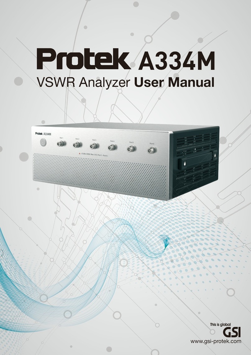
PRO-TEK A734 User manual


2
This Operating Manual represents design, specifications, overview of
functions, and detailed operation procedure of Protek A734 Spectrum
Analyzer, to ensure effective and safe use of the technical capabilities
of the instruments by the user.
Spectrum Analyzer operation and maintenance should be performed by
qualified engineers with initial experience in operating of microwave
circuits and PC. Below you will find the abbreviations used in this
Manual:
PC - Personal Computer
DUT - Device Under Test

3
INTRODUCTION....................................................................................................... 2
1 SAFETY INSTRUCTIONS ................................................................................10
2 GENERAL OVERVIEW ...................................................................................15
2.1 Description ..........................................................................................18
2.2 Specifications ......................................................................................19
2.3 Options and Accessories ......................................................................23
2.4 Principle of Operation.......................................................................... 27
3 PREPARTION FOR USE ..................................................................................30
3.1 Power Adaptor ....................................................................................30
3.2 Battery.................................................................................................31
3.3 Front Panel ..........................................................................................37
3.4 Top Panel.............................................................................................44
3.5 Side Panel............................................................................................46
4 Operation and Function................................................................................50
4.1 Freq (Frequency)..................................................................................53
4.1.1 Center Freq(F1)........................................................................55
4.1.2 Start Freq(F2)...........................................................................59
4.1.3 Stop Freq(F3) ...........................................................................62
4.1.4 CF Step(F4) ..............................................................................66
4.2 Span.................................................................................................... 69
4.2.1 Set Span(F1) ............................................................................71
4.2.2 Full Span(F2)............................................................................76
4.2.3 Zero Span(F3) ..........................................................................78
4.3 Amp (Amplitude) ................................................................................81
4.3.1 Ref Level(F1) ............................................................................83
4.3.2 Scale/Div(F2)............................................................................88
4.3.3 Unit(F3) ...................................................................................89
4.3.4 Atten(F4) .................................................................................92
4.3.5 Preamp(F5) ..............................................................................94
4.3.6 Ref Offset(F6) ..........................................................................96
4.4 BW/SWP (Bandwidth/Sweep)..............................................................99
4.4.1 RBW(F1) ................................................................................101
4.4.2 VBW(F2) ................................................................................105
4.4.3 SWP Type(F3)......................................................................... 109
4.4.4 SWP Time(F4) ........................................................................113

4
4.4.5 Detector(F5) ..........................................................................116
4.4.6 Ref. Clock(F6) ........................................................................119
4.5 Marker ..............................................................................................122
4.5.1 Marker(F1)............................................................................. 125
4.5.2 Normal(F2).............................................................................126
4.5.3 Delta(F3)................................................................................ 130
4.5.4 Off(F4)................................................................................... 135
4.5.5 Marker CF(F5)..................................................................... 136
4.5.6 Marker All Off(F6)..................................................................138
4.6 Trace .................................................................................................139
4.6.1 Trace(F1)................................................................................141
4.6.2 Clear Write(F2).......................................................................142
4.6.3 Max Hold(F3).........................................................................144
4.6.4 Hold(F4).................................................................................146
4.6.5 Off(F5)................................................................................... 147
4.6.6 Average(F6) ...........................................................................148
4.7 Peak ..................................................................................................150
4.7.1 Peak Search(F1) .....................................................................153
4.7.2 Next Peak(F2).........................................................................154
4.7.3 PeakCF(F3) .........................................................................156
4.8 Meas (Measure) ................................................................................158
4.8.1 Measure Off(F1).....................................................................160
4.8.2 Ch Power(F2).........................................................................161
4.8.3 ACP(F3) .................................................................................165
4.8.4 Harmonic(F4).........................................................................168
4.8.5 Phase Noise(F5) .....................................................................170
4.8.6 Demod(F1).............................................................................171
4.8.7 Pwr Sensor(F2).......................................................................174
4.9 System...............................................................................................185
4.9.1 File(F1)...................................................................................187
4.9.2 Setting(F2).............................................................................198
4.9.3 Lo/Re(F3) ...............................................................................213
4.9.4 SW Upgrade(F4) ....................................................................216
4.9.5 Information(F5)......................................................................218
4.9.6 Preset(F1) ..............................................................................220
4.9.7 Limit Line(F2) .........................................................................226
5 WARRANTY INFORMATION ........................................................................240

5
Figure
Figure 2-1 A734 Hand-Held Spectrum Analyzer.................................... 18
Figure 2-2 A734 Option & Accessories.................................................. 23
Figure 2-3 A734 Block-diagram ............................................................27
Figure 3-1 Connecting the power adaptor ............................................30
Figure 3-2 Battery.................................................................................31
Figure 3-3 A734 bottom view...............................................................33
Figure 3-4 Battery Charger Cradle.........................................................34
Figure 3-5 A734 Front View..................................................................37
Figure 3-6 A734 Top View ....................................................................44
Figure 3-7 A734 Side View ...................................................................46
Figure 4-1 Main Window......................................................................50
Figure 4-2 Frequency Control Key .........................................................53
Figure 4-3 Frequency Menu-tree...........................................................54
Figure 4-4 Center Frequency Control (Up/Down Key & Rotary) ............. 58
Figure 4-5 Span Control Key .................................................................69
Figure 4-6 Span Menu-tree...................................................................70
Figure 4-7 Span Control (Up/Down Key & Rotary).................................74
Figure 4-8 Amplitude Control Key.........................................................81
Figure 4-9 Amplitude Menu-tree ..........................................................82
Figure 4-10 Reference Level Control (Up/Down Key & Rotary) ..............86
Figure 4-11 Bandwidth & Sweep Control Key........................................99
Figure 4-12 BW/SWP Menu-tree.........................................................100
Figure 4-13 RBW Control (Up/Down Key & Rotary).............................103
Figure 4-14 VBW Control (Up/Down Key & Rotary)............................. 107
Figure 4-15 SWP Time Menu-tree.......................................................113
Figure 4-16 Detector Menu-tree .........................................................116
Figure 4-17 Marker Control Key..........................................................123
Figure 4-18 Marker Menu-tree ...........................................................124
Figure 4-19 Marker Control (Up/Down Key & Rotary) .........................129
Figure 4-20 Delta Marker Control (Up/Down Key & Rotary) ................134
Figure 4-21 Trace Control Key.............................................................139
Figure 4-22 Trace Menu-tree ..............................................................140
Figure 4-23 Average Menu-tree..........................................................148
Figure 4-24 Peak Control Key..............................................................151
Figure 4-25 Peak Menu-tree ...............................................................151
Figure 4-26 Measure Control Key........................................................158
Figure 4-27 Measure Menu-tree .........................................................159

6
Figure 4-28 Channel Power Menu-tree ...............................................161
Figure 4-29 ACP Menu-tree................................................................165
Figure 4-30 Demodulation Menu-tree ................................................172
Figure 4-31 Power Sensor Menu-tree..................................................174
Figure 4-32 System Control Key ..........................................................185
Figure 4-33 System Menu-tree............................................................ 186
Figure 4-34 File Menu-tree .................................................................188
Figure 4-35 Save Menu-tree ...............................................................190
Figure 4-36 Load Menu-tree ...............................................................192
Figure 4-37 Manager Menu-tree.........................................................194
Figure 4-38 Setting Menu-tree............................................................198
Figure 4-39 Date/Time Menu-tree ......................................................200
Figure 4-40 IP Set Menu-tree ..............................................................207
Figure 4-41 Sound Menu-tree.............................................................210
Figure 4-42 Volume Control (Up/Down Key & Rotary).........................212
Figure 4-43 Local & Remote Menu-tree ..............................................214
Figure 4-44 Preset Menu-tree .............................................................220
Figure 4-45 Load Type Menu-tree .......................................................222
Figure 4-46 Limit Line Menu-tree........................................................226
Table
Table 2-1 A734 Specifications...............................................................19
Table 2-2 Option & Accessory Descriptions............................................24
Table 3-1 External Power Indicator LED .................................................35
Table 3-2 Battery Charging Status LED ..................................................35
Table 3-3 Environment Specifications.................................................... 36
Table 3-4 Character Assignment ...........................................................41
Table 4-1 Main Window Descriptions.................................................... 50
Table 4-2 Frequency Menu Descriptions................................................54
Table 4-3 Chancing Center Frequency (with Numeric Key) .................... 56
Table 4-4 Center Frequency Active & De-active .....................................57
Table 4-5 Changing Center Frequency (Up/Down Key & Rotary knob)...58
Table 4-6 Changing Start frequency ......................................................61
Table 4-7 Start Frequency Active & De-active ........................................ 62
Table 4-8 Changing Stop Frequency...................................................... 65
Table 4-9 Stop Frequency Active & De-active.........................................65
Table 4-10 Changing CF Step................................................................67
Table 4-11 CF Step Active & De-active...................................................68

7
Table 4-12 Span Menu Descriptions......................................................70
Table 4-13 Changing Set Span (with number keys) ............................... 73
Table 4-14 Set Span Active & De-active.................................................73
Table 4-15 Changing Span (Up/Down Key & Rotary knob) .................... 75
Table 4-16 Chancing Zero Span (number keys) .....................................80
Table 4-17 Zero Span Active & De-active............................................... 80
Table 4-18 Amplitude Menu Descriptions .............................................82
Table 4-19 Changing Ref Level (number keys).......................................85
Table 4-20 Ref Level Active & De-active.................................................85
Table 4-21 Changing Ref Level (Up/Down Key & Rotary knob) .............. 86
Table 4-22 Changing Ref Offset (number keys) .....................................98
Table 4-23 Ref Offset Active & De-active...............................................98
Table 4-24 BW/SWP Menu Descriptions.............................................. 100
Table 4-25 RBW Active & De-active.....................................................104
Table 4-26 RBW Manual Changing (Up/Down Key & Rotary knob)...... 104
Table 4-27 VBW Active & De-active.....................................................108
Table 4-28 Changing VBW Manually (Up/Down Key & Rotary knob) ... 108
Table 4-29 Ext. Trigger Setting ............................................................112
Table 4-30 Trigger Descriptions ...........................................................112
Table 4-31 Marker Menu Descriptions.................................................124
Table 4-32 Changing Normal Marker Frequency (with number keys)...128
Table 4-33 Normal Active & De-active .................................................128
Table 4-34 Changing Normal Marker Frequency (Up/Down Key & Rotary
knob) .........................................................................................129
Table 4-35 Changing Delta Marker Frequency (with number keys) ......132
Table 4-36 Delta Active & De-active ....................................................133
Table 4-37 Changing Delta Marker Frequency (Up/Down Key & Rotary
knob) .........................................................................................134
Table 4-38 Trace Menu Descriptions.................................................... 140
Table 4-39 Peak Menu Descriptions ....................................................152
Table 4-40 Measure Menu Descriptions ..............................................159
Table 4-41 Power Sensor Menu Descriptions....................................... 174
Table 4-42 System Menu Descriptions................................................. 186
Table 4-43 File Menu Descriptions ......................................................188
Table 4-44 Manager Menu Descriptions..............................................194
Table 4-45 Setting Menu Descriptions................................................. 198
Table 4-46 Date & Time Menu Descriptions.........................................200
Table 4-47 IP Set Menu Descriptions ...................................................207
Table 4-48 Sound Menu Descriptions.................................................. 210
Table 4-49 Volume Control (Up/Down Key & Rotary knob) .................212

8
Table 4-50 Volume Control Step .........................................................213
Table 4-51 Lo/Re Menu Descriptions...................................................214
Table 4-52 Preset Menu Descriptions ..................................................221
Table 4-53 Load Type Menu Descriptions ............................................222
Table 4-54 Limit Line Menu Descriptions............................................. 226

OPERATING
MANUAL
SAFETY
INSTRUCTION
1

10
Carefully read through the following safety instructions before putting the
Analyzer into operation. Observe all the precautions and warnings
provided in this Manual for all the phases of operation, service, and repair
of the Analyzer.
The Analyzer must be used only by skilled and specialized staff or
thoroughly trained personnel with the required skills and knowledge of
safety precautions.
The protection provided by the equipment may be impaired if the
equipment is used in a manner not specified by the manufacturer.
A734 is tested in stand-alone condition or in combination with the
accessories supplied by GSI against the requirement of the standards
described in the Certificate of Compliance. If it is used as a system
component, compliance of related regulations and safety requirements are
to be confirmed by the builder of the system.
Never operate the Analyzer in the environment containing inflammable
gasses or fumes.
Operators must not remove the cover or part of the housing. The Analyzer
must not be repaired by the operator. Component replacement or internal
adjustment must be performed by qualified maintenance personnel only.
Never operate the Analyzer if the power cable is damaged.
Never connect the test terminals to mains.
If the equipment is used in a manner not specified by the manufacturer,
the protection provided by the equipment may be impaired.
Electrostatic discharge can damage your Analyzer when connected or
disconnected from the DUT. Static charge can build up on your body and
damage the sensitive circuits of internal components of both the Analyzer
and the DUT. To avoid damage from electric discharge, observe the

11
following:
-Always use a desktop anti static mat under the DUT.
-Always wear a grounding wrist strap connected to the desktop
anti static mat via daisy-chained 1 MΩ resistor.
Observe all the general safety precautions related to operation of
equipment powered by mains.
The definitions of safety symbols used on the instrument or in the Manual
are listed below.
Refers to the Manual if the instrument is marked with this
symbol.
This sign denotes a hazard. It calls attention to a
procedure, practice, or condition that, if not correctly
performed or adhered to, could result in injury or death to
personnel.
This sign denotes important information. It calls
attention to a procedure, practice, or condition that
is essential for the user to understand.
The equipment should be operated using the supplied Power

12
Adaptor.
The power connection plug must only be plugged into a two-pin
grounded socket!
Do not use any battery except for specified battery.
Li-Ion batteries must not be exposed to high temperatures or fire.
Keep batteries away from children.
Do not short-circuit the battery.
Li-Ion batteries are suitable for environmentally-friendly disposal
or specialized recycling.
If the battery is replaced improperly, there is danger of explosion.
Never use solvents such as thinners, acetone and similar things,
as they may damage the front panel labeling or plastic parts
Cleaning
This section provides the cleaning instructions required for
maintaining the proper operation of your Spectrum.
To remove contamination from parts other than test ports and
any connectors of the Spectrum, wipe them gently with a soft
cloth that is dry or wetted with a small amount of water and
wrung tightly.
It is essential to keep the test ports always clean as any dust or
stains on them can significantly affect the measurement
capabilities of the instrument. To clean the test ports (as well as
other connectors of the Analyzer), use the following procedure:
-using compressed air remove or loosen the contamination
particles;
-clean the connectors using a lint-free cleaning cloth wetted with
a small amount of ethanol and isopropyl alcohol (when cleaning
a female connector, avoid snagging the cloth on the center
conductor contact fingers by using short strokes);
-dry the connector with low-pressure compressed air.
Always completely dry a connector before using it.

13
Never use water or abrasives for cleaning any connectors of the
Analyzer.
Do not allow contact of alcohol to the surface of the insulators
of the connectors.
When connecting male-female coaxial connectors always use a
calibrated wrench.
Caution
Never perform cleaning of the instrument if the power
cable is connected to the power outlet.
Never clean the internal components of the instrument.
Storage
Before first use store your equipment in the factory package at
environment temperature from 0 to +50ºС and relative
humidity up to 95% (at 25 ºС).
After you have removed the factory package store the
equipment at environment temperature from +10 to +35ºС and
relative humidity up to 80% (at 25 ºС).
Ensure to keep the storage facilities free from dust, fumes of
acids and alkalis, aggressive gases, and other chemicals, which
can cause corrosion

14
+82-32-1688-6820
GS Instruments Co., Ltd.
70, Gilpa-ro 71beon-gil, Nam-gu, Incheon,
402-854, Korea
Product Information and Technical Assistance
www.gsinstrument.com

15

16

OPERATING
MANUAL
GENERAL
OVERVIEW
2

18
A734 is Hand-Held type spectrum analyzer with a frequency range of 100
kHz to 4.4 GHz.
This equipment is suitable for signal analysis which can be used as
frequency, digital information are more important these days.
A734 Hand-Held Spectrum Analyzer has been designed for use in the
process of development, adjustment and testing of various electronic
devices in industrial and laboratory facilities, including operation as a
component of an automated measurement system.
The equipment provides a variety of functions and user-friendly interface
so user can operate for management and test about frequency and
amplitude.
Figure 2-1 A734 Hand-Held Spectrum Analyzer

19
Protek A734 has wide frequency range of 100 kHz to 4.4 GHz and provides
analysis ability which can measure low level RF signal with preamp.
The equipment has low power consumption so that A734 can operate for
8 hours with the battery.
Item
Specification
Frequency
Range
100 kHz to 4.4GHz
Span Mode
Center Freq + Span or Start Freq +
Stop Freq ,ZERO Span
Span
ZERO SPAN , 600 Hz to 4.4GHz
Minimum Span
600 Hz
Internal Frequency
Reference Accuracy
±1PPM
Frequency Readout
Accuracy
Reference error ±1 sample1
Marker Accuracy
Reference error ±1 sample
RBW
Span 에dependent
0.1Hz to 250kHz & 5MHz(0.1, 0.2,
0.4 ,0.8, 1.6, 3.2, 6.5, 13, 25, 50, 100
Hz or kHz)
Amplitude
Measurement Range
DANL - 1dB Gain Compression
1dB Gain Compression(attenuator
15dB, preamp off)
+16dBm Typical, 1Hz to 150MHz
+19dBm Typical, 150MHz to 4.4GHz
DANL
Displayed Average Noise Level : 0dB
ATT, 1Hz RBW
FREQ
Preamp
OFF
Preamp
ON
1
1 sample represents approximately 40% of the selected RBW.

20
10Hz
-124dBm
NA
100Hz to
10kHz
-130dBm
NA
10kHz to
500kHz
-142dBm
NA
500kHz to
10MHz
-142dBm
-153dBm
10MHz to
100MHz
-148dBm
-161dBm
100MHz to
1GHz
-144dBm
-158dBm
1GHz to
2.6GHz
-139dBm
-151dBm
2.6GHz to
3.3GHz
-135dBm
-151dBm
3.3GHz to
4.4GHz
-128dBm
-134dBm
Amplitude unit
dBm, Watt
Absolute Accuracy
(ref level < 0dBm)
±1.5dB Typical
Absolute Accuracy
(0dBm< ref level <
10dBm
±1.5dB
Relative Accuracy
(ref level < 0dBm)
±0.25
Maximun Safe Input
Level
( preamp off, 15dB att)
+20dBm
DC Volt
±0.2V max
Sweep
Zero Span Sweep Time
10 ms to 2 sec ( ±0.1% )
All other sweep times are estimates
reported after sweep completes
Sweep Triger
freerun, single, external
External Trigger
3.3V CMOS/TTL input
Display
TRACE
3 Trace
Other manuals for A734
1
Table of contents
Other PRO-TEK Measuring Instrument manuals
PRO-TEK
PRO-TEK A334M User manual
PRO-TEK
PRO-TEK 1006 User manual
PRO-TEK
PRO-TEK Z9216 User manual
PRO-TEK
PRO-TEK 9216A User manual
PRO-TEK
PRO-TEK B8000FD Series User manual
PRO-TEK
PRO-TEK WI Series User manual
PRO-TEK
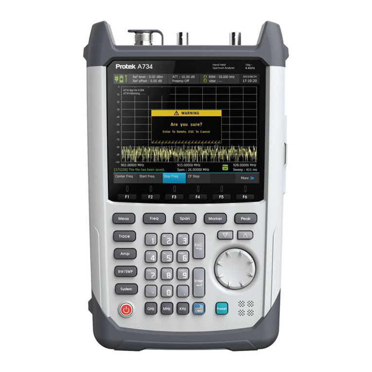
PRO-TEK A734 User manual
PRO-TEK
PRO-TEK A434L User manual
PRO-TEK
PRO-TEK B-810 User manual

PRO-TEK
PRO-TEK 3201 User manual
Popular Measuring Instrument manuals by other brands
LSI LASTEM
LSI LASTEM Sphensor PRMPA0401 user manual

marposs
marposs M1 Star MBG instruction manual
X-Rite
X-Rite 891 Operation manual

Hilti
Hilti HILTI PD-C operating instructions
Agilent Technologies
Agilent Technologies E8363BU/CU-068 Installation note
Extech Instruments
Extech Instruments 461893 user manual
