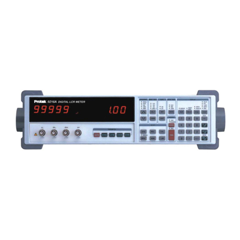
PRO-TEK Z9216 User manual

High Accuracy, Wide Range LCR Meter
Z9216
SPECIFICATIONS
30
Measured Components
L (inductance)
C (capacitance)
R (resistance)
Measured Circuit Configurations: series and parallel
Measurements
Resistance
Measured Parameter: R + Q
Measurement Ranges: R: 0.0001 Ωto 2000 MΩ
Q: 0.00001 to 50
Inductance
Measured Parameter: L + Q
Measurement Range: L: 0.0001 µH to 99999 H
Q: 0.0001 to 50
Capacitance
Measured Parameters: C + D and C + R
Measurement Range: C: 0.0001 pf to 99999 µF
D: 0.00001 to 10; R: 0.00001 KΩto 9999 KΩ
Display: Values, % deviation, or bin number
Test Environment
Test Frequencies: 100Hz, 120Hz, 1kHz, 10kHz and 100kHz
Frequency Accuracy: #±100 PPM
Drive Voltages: Fixed: 0.10, 0.25, 1.0 V RMS;
Vernier: 0.1 to 1.0 V RMS (50 mV resolution)
Drive Voltage Accuracy: ±2%
Measurement Rates:
(For test frequencies of 1kHz or greater):
Slow: 2 measurements/Sec
Medium: 10 measurements/Sec
Fast: 20 measurements/Sec
(For test frequencies of 100Hz and 120Hz):
Slow: 0.6 measurements/Sec
Medium: 2.4 measurements/Sec
Fast: 6 measurements/Sec
Bias Voltage: Internal: +2.0 V DC ±2%;
External: 0 to +40 V DC
Input Protection: 0.25A/250V Fuse
Ranging: Auto or manual
Triggering: Continuous, manual or remote (from the RS-232,
GPIB or handler interface)
Measurement Accuracy
Basic Accuracy: ± 0.2% with the following conditions:
1. An ambient temperature of 23°C ±5°C after a 30 minute
warm up period.
2. The short and open Cal has been performed.
3. D < 0.1 for capacitance, Q < 0.1 for resistance and Q > 10 for
inductance.
The component value, measurement rate and frequency
determine the actual measurement accuracy. (See the user
manual).
Zeroing Correction: Open and short circuit compensation
Remote Operation: Interfaces: RS-232 (25 pin D female
conductor) Standard GPIB and Handler (25 pin D male
connector optional)
General Specifications
AC Voltage Input: 120/220 Volts
Frequency: 50/60Hz
Power Consumption: 20 Watts
Operating Temperature: 0 to 50°C at < 80% Relative Humidity
Size: 4.3" H × 14.3" W × 14.5" D
Weight: 18 lbs.
Supplied Accessories: Manual, Line cord, Axial lead adapter
Optional Accessories: GPIB and Handler interface, Kelvin
clips, SMD tweezers
0.2% basic accuracy
Wide measurement range over13 orders of magnitude
Store and recall 9 instrument setups
Measurement rates to 20 times per second
Test frequencies are 100Hz, 120Hz, 1kHz, 10kHz and 100kHz
Displays component value and Q or Dissipation factor
Averaging for 2 to 10 measurements
RS-232 and optional GPIB and Handler interface
Open and short circuit compensation for accurate zeroing
Easy to use and calibrate
Built-in calibration procedures
Binning capabilities
K
K
K
K
K
K
K
K
K
K
K
K
Z9216
CE
Protek Test & Measurement
40 Boroline Road, Allendale, NJ 07401 Tel: 201-760-9898 Fax: 201-760-9888

High Accuracy, Wide Range LCR Meter Z9216
ACCESSORIES
31
The standard accessory supplied with the Z9216. This
unit adapts to the Z9216 input BNC terminals and
facilitates easy measurement of Axial or Radial lead
components.
The Kelvin clips provide a 4-wire connection to
components that have large or odd shaped leads. This
removes any error caused by voltage drops in the
leads.
The SMD tweezers are used to
measure small surface mount or odd
shaped components.
Display
5 digit primary LED Display
for reading component
values
5 digit secondary display for
reading Q, D or R
Frequency
Five measurement
frequencies
(100Hz, 120Hz, 1kHz,
10kHz and 100kHz)
Drive Voltages
4 preset drive voltages
from 0.1 to 1V and
constant voltage output
Bias
Internal or external bias for
measuring capacitors
Meas. Rate
Measurement rates of 2, 10 or 20
measurements per second in
continuous or triggered mode
Display
2 to 10 measurement average
Range hold mode
Series or parallel circuit
models
Display component value,
Deviation, % deviation and Bin
number displays
Parameter entry keys
Output terminals
4-wire output: 2 terminals supply
the drive signal and 2 terminals
for sensing, thereby removing
lead error
Parameter Keys
Auto key, automatic selection of the
appropriate component
Resistance + Q
Inductance + Q
Capacitance + D
Capacitance + R
Setup
Store and recall 9 setups
Binning parameter setup
Calibration performs open and short calibration
Standard calibration
Internal self-tests
Vernier amplitude drive voltages from 0.1 to 1V
in 50mV increments
Setting settling time
Numeric keyboard
For entering measurement
conditions and values.
K
K
K
K
K
K
K
K
K
K
K
K
K
K
K
K
K
K
Protek Test & Measurement
40 Boroline Road, Allendale, NJ 07401 Tel: 201-760-9898 Fax: 201-760-9888


Chapter
1
Background on Components and Measurements
Properties of Resistors, Inductors, and Capacitors
The measurements made by the Model Z9216, Digital LCR Meter are based on the definitions of
impedance and the properties of discrete components designed to provide impedances in electronic
circuits.
Definitions of Resistive and Reactive Parameters
Let the sinusoidal voltage and current in an electronic circuit at a particular frequency, f be
represented in the complex or phasor notation, given by
(
)
v
tVtV
θ
ω
+
=cos||)( (1a)
(
)
(
)
tj
jtj eeVeV vv
ω
θθω
|||| == +(1b)
(
)
i
tItI
θ
ω
+
=cos||)( (2a)
(
)
(
)
tj
jtj eeIeI ii
ω
θθω
|||| == +(2b)
where 1−=j, ω=2πf, and v
θ
and i
θ
are symbols for phases of the voltage and current relative to
the frequency f. The impedance of a circuit component is defined as the complex number Z, in ohms,
that gives the ratio of the voltage across the component to the current in the component:
()
(
)
() (
iv
i
vj
tj
tj
e
I
V
eI
eV
tI
tV
ZZ
θθ
θω
θω
ω
−
+
+
==== ||
||
||
||
)(
)(
)
(3)
Component Categories
From equation (3), we observe that if the phases of the voltage across the component and the current
in it are equal, then the impedance is a real number:
()
||
||
||
|| 0
I
V
e
I
V
Zj== (4)
In this situation, the impedance is purely resistive, as an ideal resistor would be.
If the phase of the voltage is 90 degrees (π/2 radians) ahead of the phase of the current, then the
impedance is a positive imaginary number:
()
||
||
||
|| 2/
I
V
je
I
V
Zj==
π
(5)
1

In this situation of positive, imaginary impedance, the impedance is purely inductive, as an ideal
inductor would be. The impedance of an ideal inductor with inductance L is a linear function of
frequency, given by ZL =jωL.
If the phase of the voltage is 90 degrees (π/2 radians) behind the phase of the current, then the
impedance is a negative imaginary number:
()
||
||
||
|| 2/
I
V
je
I
V
Zj−== −
π
(6)
In this situation of negative, imaginary impedance, the impedance is purely capacitive, as an ideal
capacitor would be. The impedance of an ideal capacitor with capacitance C is the inverse of a linear
function of frequency, given by ZC = 1 / jωC =−j/.ωC.
Actual circuit components are not purely resistive, inductive, or capacitive. From a practical
standpoint, capacitors and inductors have impedances with resistive parts, and their impedances
may not be linear functions of frequency or independent of the voltage. The general expression for
impedance, considers a real part containing the resistive component of the entire impedance, R, and
the reactance or imaginary part of the impedance, being Xl, Xc, or the algebraic sum of the two. This
complex impedance is represented by:
Z=R +jX, (7)
Where X =ωL for an inductor and X =−1/ωC for a capacitor. Since the quantity X is traceable to the
ratio of a voltage to a current, it is expressed in ohms. Often, it is desirable to express the impedance
in ohms as a scalar (real) quantity; in that case, its magnitude 22
|XRZ +=|is used.
Units
The unit of resistance is the ohm, with the symbol Ω(omega). A 1-Ωresistor drops 1 volt across its
terminals when one Ampere is flowing through the resistor.
The unit of inductance is the Henry, with the symbol H. For a one-amp AC current, a 1-H inductor
would produce an AC voltage across it whose magnitude is numerically equal to 2πtimes the
frequency in Hertz.
The unit of capacitance is the Farad, with the symbol F. For a one-amp AC current, a 1-F
capacitor would produce an AC voltage across it whose magnitude is numerically equal to the inverse
of 2πtimes the frequency in Hertz.
2

Series and Parallel Equivalent Circuits
The impedances of Actual resistors, inductors and capacitors are combinations of resistance,
inductance, and capacitance. The simplest models for actual inductors and capacitors are the series
and parallel equivalent circuits shown in Figure 1-1.
For example, the complex impedance of an inductor is
LjRjXRZ
ω
+=+= (series equivalent circuit) (8a)
(
)
()
2
/1
/
pp
pppp
pp
pp
LR
LRjRR
LjR
LjR
ω
ω
ω
ω
+
+
=
+
⋅
=(parallel equivalent) (8b)
8a - Inductor Series
Equivalent
8b - Inductor Parallel
Equivalent
9a -Capacitor Series
Equivalent
9b - Capacitor Parallel
Equivalent
Figure 1-1 Equivalent circuits for inductors and capacitors.
The complex impedance of a capacitor is
CjRjXRZ
ω
/−=+= (series equivalent circuit) (9a)
(
)
()
2
1
1
1/1
/1
pp
ppp
pp
p
pp
pp
RC
RCjR
RCj
R
CjR
CjR
ω
ω
ωω
ω
+
−
=
+
=
+
⋅
=(parallel equivalent) (9b)
3

Quality Factor
Originally, the quality factor, Qwas defined for an inductor as a measure of the efficiency of energy
storage in the inductor when an AC current is passed through it. Mathematically, the definition is1
Q=2π(max. energy stored) ÷(energy dissipated per Hz) (10a)
=2πf(max. energy stored) ÷(average power dissipated) (10b)
Since the average power dissipated in the inductor with series resistance Ris |I|2Rand the maximum
energy stored in the inductor is L|I|2, the quality factor for an inductor is given by
Q= ωL/ R. (11a)
By equating (8a) and (8b), the series equivalent circuit parameters Rand Lcan be expressed in terms
of the parallel parameters Rpand Lp. When that is done and substituted in equation (10a), we find that
the quality factor also is written
Q= Rp/ ωLp. (11b)
While the concept of the quality factor was originally applied to inductors, it may be extended so
that the efficiency of energy storage in a capacitor may be expressed in terms of the circuit
components and frequency. Thus, if the series resistance and capacitance of a capacitor are,
respectively, Rand Cas in Figure 1-1, then (10b) is evaluated to be
Q= 1 / ωCR. (12a)
By equating (9a) and (9b), the series equivalent circuit parameters Rand Ccan be expressed in terms
of the parallel parameters Rpand Cp. When that is done and substituted in equation (12a), we find that
the quality factor for a capacitor also is written
Q= ωCpRp. (12b)
4
1W. L. Everett and G. E. Anner, Communication Engineering, McGraw-Hill, New York, 1956.

Using the quality factor, the impedance of an inductor is seen to be
(
)
(
)
QjLjQRLjRZ /11
+
=
+
=
+=
ω
ω
(13a)
and the inductor’s series equivalent circuit components can be expressed in terms of its parallel
equivalent circuit components as
2
1Q
R
Rp
+
=, 2
2
1Q
LQ
Lp
+
=(13b)
The impedance of a capacitor in terms of the quality factor is
()(
jD
C
jQRCjRZ −=−=+=
ω
ω
1
1/1
)
(14a)
and the capacitor’s series equivalent circuit components can be expressed in terms of its parallel
equivalent circuit components as
2
1Q
R
Rp
+
=,
(
)
p
CDC 2
1+= (14b)
5

Chapter
2
Accuracy and Calibration
How to Assess and Control the Accuracy
The accuracy achieved by the Model Z9216 Digital LCR Meter depends on several factors. In this
chapter, equations are given for estimating the accuracy of a specific measurement, and procedures
are given for calibrating the meter.
Accuracy Specifications
Note: The accuracy of the Model Z9216 that is stated in this chapter is valid for the following
conditions: (a) a warm-up time of at least 30 minutes, (b) a temperature of 23°C ±5°C, (73°F±9°F) (c)
the use of the built-in fixture, and (d) the completion of the open and short circuit calibrations. In
addition, the component being measured must have the following characteristic: D < 0.1 for a
capacitor, Q < 0.1 for a resistor, or Q > 10 for an inductor.
General Accuracy Equation
The accuracy of a measurement is a function of the “basic impedance accuracy” at the specific
frequency, measurement rate, signal amplitude, and the impedance of the device under test (DUT)
relative to the measurement range. The basic instrument accuracy can be determined from graphs
given below. Additional factors affecting the accuracy are related to the measurement conditions and
the impedance of the DUT. From these, the accuracy of a particular measurement in its optimal
range is calculated. See below for the effects on measurements made out of an optimal range.
The basic equation for impedance measurement accuracy equation is given by:
A z(measured) % =± [Az×Ki× Kv+ 100 ×(Kh+Kl)], where (1)
Az=the basic impedance accuracy from Figure 2-1, which should be multiplied by two if the unit
is in constant voltage mode. Figure 2-1 is based on the fact that the best accuracy occurs
when the impedance to be measured is greater than ¼ the source resistance and less than 4
times that resistance, and when the test frequency is 1 kHz or less.
Ki=integration time factor, as given in Table 2-1.
Kv=drive voltage error factor, as given in Table 2-2. Note from Table 2-2 that Kvis defined as
equal to 1.0 for the primary drive voltages (1.0, 0.5, and 0.25 Vrms).
Kh, Kl=extreme range error terms, as given in Table 2-3. Note from Table 2-3 that Klis
negligible for impedances above 100 Ωand Khis negligible for impedances below 1 kΩ, both
at all frequencies.
6

.55% .35% .55%
.35% .25% .35%
0.20%
Figure 2-1 Basic Impedance Accuracy
Table 2-1 - Integration Time Accuracy Factor, Ki
Meas. Rate Frequency ZmKi
Slow, Medium All All 1
Fast 100 Hz to 1 kHz 6.25 Ω< Zm< 400 kΩ3
All other 2
Table 2-2 - -Drive Voltage Error Factor, Kv
Vout (Vrms) Kv
0.55 to 1.0 1/Vout
0.3 to 0.5 0.5/Vout
0.15 to 0.25 0.25/Vout
0.10 0.11/Vout
7

Table 2-3 - Extreme Range Error Terms For Impedance and Resistance, Khand Kl
Frequency KlKh
100 Hz, 120 Hz, 1 kHz (1 mΩ/Zm) (Zm/2 GΩ)
10 kHz (1 mΩ/Zm) (Zm/1.5 GΩ)
100 kHz (4 mΩ/Zm) (Zm/50 MΩ)
Accuracy Equations for Specific Measurement Modes
R + Q Accuracy
In the R + Q measurement mode, the basic impedance accuracy, Az, in equation (1), may be read
from Figure 2-1 directly while interpreting the “impedance” as “resistance.” The resistance accuracy is
calculated from equation (2a), with the additional stipulation that if the measured Q has an absolute
value greater than 0.1, then the basic resistance accuracy factor should be multiplied by the factor (1
+ |Q|).
A
r(measured) % =± [Ar ×Ki× Kv+ 100 ×(Kh+Kl) (2a)
Where A r(measured) % is the measured or published resistance accuracy and Ar is the basic
resistance accuracy. The basic resistance accuracy, Ar, which can be taken from Figure 2-1 by
substituting impedance, Z, with resistance, R.
With the basic resistance accuracy factor denoted Ar. The accuracy of the measurement of Q is given
by:
Accuracy of Q = ± [(Ar/100) ×(1+Q2)] (2b)
Note that the accuracy of Q is specified as a magnitude, not as a percentage.
L+Q Accuracy
The basic impedance accuracy depicted in Figure 2-1 applies to inductance measurements when the
impedance is interpreted to be 2πf L, where fis the test frequency in Hz and L is the inductance in
Henrys. For convenience, Figure 2-1 is redrawn as Figure 2-2 with lines of constant inductance
superimposed. Also, Table 2-3 is recreated for inductive impedances and named as Table 2-4. Note
from Table 2-4 that the range error factor Klis negligible for inductances above 15.9/fH and Khis
negligible for inductances below 159/fH.
The accuracy of the inductance measurement, Al (measured), is calculated by applying equation (3a),
with the additional stipulation that if the measured Q has an absolute value less than 10, then the
basic inductance accuracy factor, Al, should be multiplied by the factor (1 + |1/Q|).
Al (measured) % =± [ Al ×Ki× Kv+ 100 ×(Kh+Kl)] (3a)
8
Then the accuracy of the Q calculation is given by equation (3b)
Accuracy of Q = ± [(Al/100) ×(1+Q2)] (3b)
0.55% 0.35% 0.55%
0.35% 0.25% 0.35%
0.20%
Figure 2-2 Basic Impedance Accuracy for Inductance
Table 2-4 - Extreme Range Error Terms for Inductances, Khand Kl
Frequency KlKh
100 Hz, 120 Hz (1 µH/Lm) (Lm/2.6 MH)
1 kHz (0.1 µH/Lm) (Lm/260 kH)
10 kHz (0.02 µH/Lm) (Lm/10 kH)
100 kHz (0.02 µH/Lm) (Lm/100 H)
Note: Lm = Measured Inductance Value
9

C+D Accuracy
The basic impedance accuracy depicted in Figure 2-1 applies to capacitance measurements when
the impedance is interpreted to be 1/2πf C, where fis the test frequency in Hz and C is the
capacitance in Farads. For convenience, Figure 2-1 is redrawn in Figure 2-3 with lines of constant
capacitance superimposed. Also, Table 2-3 is recreated for capacitive impedances as Table 2-5.
Note from Table 2-5 that the range error factor Klis negligible for capacitances below 1590/fµF and
Khis negligible for capacitances above 159/fµF.
The accuracy of the capacitance measurement is calculated from equation (1) above, with the
additional stipulation that if the measured D has a value less than 0.1, then the basic capacitance
accuracy factor should be multiplied by the factor (1 + D). Let the basic capacitance accuracy factor
be denoted Ac.
Ac (measured) % =± [ Ac ×Ki× Kv+ 100 ×(Kh+Kl)] (4a)
Then the accuracy of the D calculation is given by
Accuracy of D = ± [Ac/100] (4b)
Note that the accuracy of D is specified as a magnitude, not as a percentage.
0.55% 0.35% 0.55%
0.35% 0.25% 0.35%
0.20%
Figure 2-3 Basic Impedance Accuracy for Capacitances
1
0

Table 2-5 Extreme Range Error Terms for Capacitances (C + D mode), Khand Kl
Frequency KlKh
100 Hz, 120 Hz (2 pF/Cm) (Cm/1600 mF)
1 kHz (0.1 pF/Cm) (Cm/160 mF)
10 kHz (0.01 pF/Cm) (Cm/16 mF)
100 kHz (0.02 pF/Cm) (Cm/200 µF)
Note: Cm = Measured Capacitance Value
Table 2-6 - Extreme Range Error Terms for Capacitances (C + R mode), Khand Kl
Frequency KlKh
100 Hz, 120 Hz (2 pF/Cm) (Cm/2000 mF)
1 kHz (0.1 pF/Cm) (Cm/200 mF)
10 kHz (0.01 pF/Cm) (Cm/10 mF)
100 kHz (0.01 pF/Cm) (Cm/100 µF)
C+R Accuracy
The basic impedance accuracy depicted in Figure 2-1 applies to capacitance measurements when
the impedance is interpreted to be 1/2πf C, where fis the test frequency in Hz and C is the
capacitance in Farads. For convenience, Figure 2-1 is redrawn in Figure 2-3 with lines of constant
capacitance superimposed. Also, Table 2-3 is recreated for capacitive impedances in the C + R
measurement mode as Table 2-6. Note from Table 2-6 that the range error factor Klis negligible for
capacitances below 1590/fµF
For small values of D (D < 0.1), the accuracy of the capacitance measurement in the C + R mode
is calculated from equation (4a) above, and the accuracy of the resistance measurement is given by
Accuracy of R in % = ± [Ac×(1 + 1/D)] (5a)
where Acis the accuracy of the capacitance measurement and
D =R/2πfC. (5b)
11

For D > 0.1, the impedance accuracy must first be calculated. To do this, first calculate the
impedance of the DUT by adding the resistive and capacitive elements, either in series or parallel, as
appropriate. Use the impedance accuracy graph to obtain an impedance accuracy, and let it be
denoted Az. The accuracies of C and R are calculated from the impedance accuracy as follows:
Accuracy of C in % = ± [Az×(1 + |D|)] (6)
Accuracy of R in % = ± [Az×(1 + 1/|D|)] (7)
Accuracy When Holding a Nonoptimal Range
When a component is measured outside of its nominal range (in range hold), the accuracy of the
measurement is reduced. The nominal ranges are defined as approximately four times above and
below the nominal impedance value:
Range Nominal Impedance Range
R3 6.25 Ωto 100 Ω
R2 100 Ωto 1.6 kΩ
R1 1.6 kΩto 25.6 kΩ
R0 (100 Hz to 10 kHz) 25.6 kΩto 400 kΩ
(R0 is not defined for 100 kHz.) Components that are measured while auto ranging have only one set
of extreme range terms (Kh, Kl) per frequency.
For components measured in the range hold mode, the values of Khand Klare different for each
range. These values are calculated from parameters tabulated below in Tables 2-7 to 2-9 for
resistive, inductive, and capacitive measurements, respectively.
Table 2-7 - Parameters for Calculating Kland Khfor Resistive Measurements
Rl=Kl×ZmRh=Kh×Zm
Frequency R3 R2 R1 R0 R3 R2 R1 R0
100, 120, 1 kHz 1 mΩ0.02 Ω0.2 Ω4 Ω400 kΩ6.5 MΩ100 MΩ2 GΩ
10 kHz 1 mΩ0.02 Ω0.2 Ω4 Ω400 kΩ6.5 MΩ100 MΩ1.5 GΩ
100 kHz 4 mΩ0.03 Ω0.4 Ω--- 200 kΩ3 MΩ50 MΩ---
1
2

Table 2-8 - Parameters for Calculating Kland Khfor Inductive Measurements
Ll=Kl×LmLh=Kh×Lm
Frequency R3 R2 R1 R0 R3 R2 R1 R0
100, 120 Hz 1 µH 20 µH 300 µH 5 mH 630 H 10 kH 160 kH 2.6 MH
1 kHz 1 µH 20 µH 300 µH 5 mH 630 H 10 kH 160 kH 2.6 MH
10 kHz 1 µH 20 µH 300 µH 5 mH 630 H 10 kH 160 kH 2.6 MH
100 kHz 1 µH 20 µH 300 µH 5 mH 630 H 10 kH 160 kH 2.6 MH
Table 2-9 - Parameters for Calculating Kland Khfor Capacitive Measurements
Cl=Kl×CmCh=Kh×Cm
Frequency R3 R2 R1 R0 R3 R2 R1 R0
100, 120 Hz 4 nF 240 pF 16 pF 2 pF 1600 mF 80 mF 6.7 mF 400 µF
1 kHz 400 pF 24 pF 1.6 pF 0.1 pF 160 mF 8 mF 670 µF 40 µF
10 kHz 40 pF 2.4 pF 0.16 pF 0.01 pF 16 mF 800 µF 40 µF 2.6 µF
100 kHz 8 pF 2.4 pF 0.02 pF --- 200 µF 80 µF 4 µF ---
1
3

Verification of Meter Performance
The performance verification procedures in this section test and verify the performance of Model
Z9216 and compare it to the specifications listed in Volume 1 of the User’s Manual. The first set of
tests verifies the basic functionality of the unit. The second set of tests verifies the critical
specifications of the Model Z9216. The results of each section can be recorded on the test sheets
located at the end of this manual.
Functional Tests
These simple tests verify the basic functionality of the Model Z9216. They are not intended to verify
the accuracy of the unit.
Necessary Equipment:
Item Critical
Specifications
Recommended Model
Analog Oscilloscope with ×10, 10MHz probes 100MHz Bandwidth Tektronix 2445
24.9 ΩResistor 0.1% Dale CMF55 or equivalent
402 ΩResistor 0.1% Dale CMF55 or equivalent
6.34 kΩResistor 0.1% Dale CMF55 or equivalent
100.0 kΩResistor 0.1% Dale CMF55 or equivalent
22 nF Capacitor 1% NPO Murata Erie RPE series or equivalent
Front Panel Test
This test verifies the front panel display digits, LEDs, and keypad.
1. Turn on the unit while holding down the DISP key. A single segment in the third digit of the left
display should be on.
2. Press the down arrow key ↓to light each segment (seven total) and the decimal for the third
and fourth digits of the left display, for a total of 16 segments. Only one segment or decimal
point should be on at a time. (Pressing the up arrow key ↑will step backward through the
pattern.)
3. Press the down arrow key ↓again (17th time) to light all the segments of all 12 digits. The
AUTO LED will also be on.
4. Press the down arrow key ↓repeatedly to light the 25 LEDs in the display and the 26 LEDs on
the keypad. The LEDs turn on one at a time, from top to bottom and left to right, first for the
display, and then for the keypad. Only one LED should be on at a time.
5. After all of the LEDs have been tested, further pressing of the front panel keys will display the
key code associated with each key. Each key has a different key code, starting with 01 at the
upper left, and increasing from top to bottom then left to right.
6. The unit must be switched off to leave this mode.
1
4

Self Tests
The internal self-tests verify the functionality of the Model Z9216. Turn on the unit. The ROM
program and model name will be displayed for about three seconds. Next the message "tESt....' will
be displayed while the unit performs its self tests. After the tests are completed the unit should display
'tESt PASS' to indicate that the tests were successful. If not, an error message will appear. See the
TROUBLESHOOTING section for a description of the error messages.
Output Voltage
This test checks the Model Z9216 output voltage for the correct frequency and amplitude.
1. Set the Model Z9216 to 1 kHz, 1 V and constant voltage. Set the scope to 1 V/div vertical and
0.5 ms/div horizontal. Connect a ×10 probe to the scope.
2. Place the tip of the probe into the "+" side of the fixture and connect the ground clip to the
center guard.
3. The scope should display a sine wave that occupies two divisions horizontally and about 5.5
divisions peak to peak vertically (1.0 Vrms - 2.83 V peak to peak). There should be no
irregularities in the waveform.
4. Change the amplitude setting of the Model Z9216 to 0.25 and 0.10 V in succession and verify
that the output is within 2% of nominal.
5. Set the amplitude back to 1.0 V. Change the Model Z9216 and scope settings to verify that
the output at 100 Hz, 120 Hz, 10 kHz and 100 kHz is within 2% of nominal.
Resistance Measurement
This test verifies that the Model Z9216 operates and is able to measure a component in each of its
ranges. The readings obtained should be within ±(tolerance of the component + tolerance of the
Model Z9216).
1. Press the key sequence RCL 0ENTER to put the unit in its default setup.
2. Perform open and short circuit calibrations for the fixture configuration to be used. See
Volume 1 for details on these null calibrations.
3. Set the unit to the R+Q measurement mode, series equivalent circuit, and 1 kHz test
frequency. Install the 24.9 Ωresistor.
4. Verify that the meter reads the resistance correctly to within ±0.15%. Verify that Q is a small
value, about +0.0001 or smaller. Install the 402 Ωresistor. Verify that the meter reads the
resistance correctly to within ±0.15%. Verify that Q is a small value, about +0.0001 or smaller.
5. Change the equivalent circuit to parallel. Install the 6.34 kΩresistor. Verify that the meter
reads the resistance correctly to within ±0.15%. Verify that Q is a small value, about −0.0001
or smaller.
6. Install the 100 kΩresistor. Verify that the meter reads the resistance correctly to within
±0.15%. Verify that Q is a small value, about −0.0002 or smaller.
1
5

Capacitance Measurement
This test verifies that the Model Z9216 is able to measure components at different frequencies.
The limits of the readings are the same as before: ±(component tolerance + meter tolerance).
1. If the fixture configuration has changed, perform open and short circuit calibration.
2. Set the Model Z9216 to the C+D measurement mode, parallel equivalent circuit, and 1 kHz
test frequency.
3. Install the 22 nF capacitor. Verify that the unit reads the capacitance correctly to within 1.10%.
Verify that D is below 0.0001.
4. Set the unit to 100 Hz. Verify that the capacitance reading is close to the value measured
above and within the tolerance stated above. Repeat for 120 Hz. D values should be below
0.0001.
5. Repeat for 10 kHz. At 10kHz, the tolerance is 1.15%. For 100 kHz the tolerance is 1.25%. D
values should be below 0.001 for 10 kHz and 0.01 for 100 kHz.
Performance Tests
These tests are intended to measure the Model Z9216's conformance with its published
specifications. These test results, along with the results of the functional tests, can be recorded
on the test sheet at the end of this manual.
Necessary Equipment
Instrument Critical Specifications
Time Interval Counter Time Interval Accuracy: 1 ns max
DC/AC Voltmeter 5 ½ digit DC accuracy, true RMS AC to 100 kHz
Resistance decade box Accuracy 0.02%: 1 Ωto 1 MΩ
Capacitance decade box Accuracy 0.02%: 1000 pF to 10 µF
Test conditions: at least 30 minutes of warm-up time, and a temperature in the range of 23°C ±5
°C (73°F ±9 °F).
.
Frequency Accuracy
This test measures the accuracy of the different output frequencies. They should be within 0.01%
(100 ppm) of the nominal value.
1. Set the Model Z9216 to its default conditions by pressing the key sequence RCL 0ENTER.
Set the unit to constant voltage mode, 1 kHz test freqency, and remove any part from the
fixture.
2. Install the BNC adapter on the fixture. Connect the IH lead to the frequency counter.
3. Verify that the frequency counter reads 1 kHz ±0.1 Hz (+0.01%). Record the result.
4. Repeat step 3 at 100 Hz, 120 Hz, 10k Hz and 100 kHz. The frequencies should all be within
0.01% of the nominal frequency. Record the results.
1
6
Table of contents
Other PRO-TEK Measuring Instrument manuals

PRO-TEK
PRO-TEK 3290N User manual

PRO-TEK
PRO-TEK 3201 User manual

PRO-TEK
PRO-TEK A734 User manual

PRO-TEK
PRO-TEK A334M User manual

PRO-TEK
PRO-TEK A734 User manual

PRO-TEK
PRO-TEK B8000FD Series User manual

PRO-TEK
PRO-TEK A434L User manual

PRO-TEK
PRO-TEK 9216A User manual

PRO-TEK
PRO-TEK WI Series User manual

PRO-TEK
PRO-TEK B-810 User manual
Popular Measuring Instrument manuals by other brands

Onset
Onset T-VER-AH02 installation guide

Alentec & Orion
Alentec & Orion 24795 user manual

Optec
Optec UMG-605-PRO User manual and technical data

Emos
Emos E0345 manual

WATANABE ELECTRIC INDUSTRY
WATANABE ELECTRIC INDUSTRY AM-212 Series instruction manual

CommScope
CommScope SYSTIMAX 360 PATCHMAX instruction sheet