PRO-TEK B-810 User manual

INST
RUCTION
MANUAL
...

l
l
I
T
‘
SWEEP
FUNCI'
ION
GENERATOR
CONTENTS
SECTlON
TITLE
PAGE
I.
GENERAL
|NFORMAT|0N
.
INTRODUCTION
2
1
2.
DESCRIPTION
3.
FEATURES
4.
SPECIFICAT|ON
5
G
.
ACCESSORIES
SUPPLIED
.
ACCESSORIES
AVAILABLE
4
IL
INSTALLATION
1.
INTRODUCTION
5
2.
PREPARATION
FOR
USE
5
1)
Power
Requirements
2)
Lino
Vohage
and
Fuse
Sebcdon
3)
Operating
Environment
‘
3.
STORAGE
ENVIRONMENT
6
lll.
OPERATION
.
1.
lNTRODUCTION
2.
PANEL
FEATURES
1)
Front
Panel
Features
7
2)
Roof
Panel
Features
10
3.
OPERATING
INSTRUCTIONS
12
1
1)
Operaüng
Proceutions
1
2
2)
Counter
(¡NT/EXT)
13
k
3)
Basic
Signal
Generation
(eine,
triengle.
square.
sync
out)
4)
Trigger/Gate
Mode
»
5)
Burst
Mode
í
6)
Sweep
Modo
4
7)
Symmetry
"i
B)
DC
Offset/DC
cut
I
9)
Amplitudo
Modulation
20
10)
veo
Operation
22
11)
Combhation
of
Funcüom
.
23
vm‘wmmmwwwwmawwww
A
""Í‘I'S‘W‘F"
w

SECTION
l
GENERAL
INFORMATION
1
.
INTRODUCTION
metían
required
to
install
and
operate
the
Sweep
strument
and
supplied
accessories.
This
section
nd
other
basic
information.
This
operating
manual
contains
the
infor
Function
Generator.
Figure
1-1
shows
the
In
covers
description,
Specifications,
accessories
a
Z.
DESCRIPTION
This
Sweep
Function
Generator
¡s
a
0.01
Hz
to
10
MHz
function
generator,
with
internal
counter
and
external
counter.
This
instrument
generates
a
variety
of
waveformes,
containing
sino,
square,
triangle,
ramp,
and
pulse
signals.
The
frequency
counters
is
built
in
6
digit,
high
seven
segment
yellow
LED
display.
Because
it
provides
such
different
operation
modes
as
continuous
generation,
gate
generation,
trigger
generation,
burst
wave
generation,
and
sweep
generation,
its
can
be
used
for
diverse
applications
-—
for
example,
for
frequency
characteristic
measurement
of
audio/video
equipment
and
in
the
testing
of
automatic
control
devices.
SWEEP
FUNCTION
GENERATOR
NIODEL
Gana
“Á

3.
FEATURES
o
Wide
frequency
range
of
0.01
Hz
to
10
MHz.
O
Frequency
counter
range
0.1
Hz
to
10
MHz
Internal:
all
range
External:
1
Hz
to
10
MHz
O
Gate
and
trigger
generations
are
possible.
‘
lt
provides
gate
generation
to
supply
signals
for
a
fixed
period
of
time,
and
trigger
generation
to
supply
signals
for
one
cycle.
The
trigger
points
can
be
arbitrarily
set.
O
Burst
waves
can
be
generated
by
the
built-in
oscillator.
O
Built-¡n
Iinear/logarithmic
sweep
functions,
O
VCG
function
for
external
control
of
output
frequency.
O
GCV
function
to
generate
a
voltage
in
proportion
to
the
frequency.
.
Built-¡n
amplitude
modulation
circuit
with
the
suppressed-carrier
mode.
-
Variable
Waveform
symmetry.
O
DC
offset
function
to
superimpose
DC
voltage
on
output
waveforms.
ln
addition,
DC
voltage
only
can
be
obtained.
4.
SPECIFICATION
1)
Frequency
Range
z
0.01
Hz-10
MHz,
9
Ranges
Accuracy
z
Counter
accuracy
Z)
Waveforms
:
Sine
wave,
triangi‘e
wave,
square
wave,
ramp
we‘ve,
and
pulse
wave
Sine
wave
Flatness
z
0.01
Hz
to
100
KHz:
i
0.2
dB
.
'
100
KHzto
10
MHz:
1:2
dB
Distortion
z
I10
lll):
to
50
KHz:
0.5%
or
less
(at
more
than
100ran-p
Output
eve
Triangle
wave
Linearity
error
:
<1%
of
rated
am
litud
guare
wave
p
e
at
100
Hz
Rise/Fall
time
.
‘
z
25
ns
or
less
(with
max.
output)
Symmetry
vanation
:
20:80
to
80:20
(0.01
Hz
to
10
MHz)
3)
Frequency
Counter
Characteristics
Frguency
measurements
Range
z
1
Hz
to
10
MHz
(¿ete
time
z
0.01
s,
0.1s,
ls,
10s
switch
selectable
ccuracy
‘
z
3:1
count/:l:
time
base
error
Ext
count
mu
characteristics
meansitivity
z
SO
mV
rms
ance
:
Approx.
1M
Max
voltage
without
O
less
then
35PF
damage
z
250V
DC+
GM!
l
AC
rms)
z
B
digit:
7mm
yellow
LED
dis
overllow,
KHz,
Hz
indication.play
WM
decimal
point
gate
time,
_3_

eration
Mode
_
4)
OP
'
Continuous
generation
h
.
.
.
n
.
I
SRv‘IlG/GATE
:
TRIG:
One
cycle
oscullatlon
triggered
la;
Input
Signs
1'
GATE:
Oscillation
only
when
Input
is
z
4
Frequency
range
z
0.1
Hz-l
MHz
g
Input
voltage
z
TTL
level
(DC
to
100
KHz)
z
Variable
'
.
.
’
\
SERE/i'm!)
phase
:
Burst
wave
oscillation
for
gate
time
of
1ms
to
103
by
built-in
,
oscillator.
'i
ON/OFF
time
is
symmetrical
and
variable.
..
Í
SWEEP
'
z
Sweep
mode:
selection
of
linear
and
logarithmic
sweeps
2
l
.
Sweep
time:
1ms
to
10s,
2
range,
contínuously
variable.
fly-back
line
interval
is
symmetrical
and
variable.
Sweep
Width:
Max.
1:
100,
contínuously
variable.
y
(sweep
start
frequency
can
be
specified.)
i
5)
Output
Characteristics
Output
level
:
20
Vp-p
(open
circuit)
Attennuator
z
O,
20,
40,
60
dB,
contínuously
variable.
lmpedance
z
5091
10%
DC
offset
:
Max.
:t
10V
(open
circuit)
SYNC
output
:
TTL
level
(duty
cycle
are
symmetrical
and
variable)
i
GCV
output
z
Voltage
output
in
proportion
to
frequency,
Gta
SV
(MAX.
frequency
in
each
range)
SWEEP
output
z
Sweep
output
in
sweep
mode,
O
to
-
SV
SWEEP/BURST
G
ATE
out
Z
TTL
level
G)
Amplitude
Modulation
(AM)
Modulation
level
z
O
to
100%,
contínuously
valiable.
Input
sugnal
level
:
Max.
5
Vp-p
suppressed-carrier
mode.
7)
VCG
(External
Control
of
Frequency)
Frequency
range
:
Max.
1000:1,
with
fre
ue
'
‘
"
"
Input
level
Z
0to
_
q
ncy
ls
dial
set
to
10
SV
li
frequency
is
decreased
by
negative
voltage
8)
Power
Requirements
z
100/120/220V
:t
10%,
240V
+
5
40%
(48
to
66
Hz)
9)
Size
and
Weight
z
300(W)
x
30
10)
Time
Base
z
Frequency;
lo
MHzOlD)
mm
Approx.
4
Kg
Aging
rate:
i
3 x
lOs/month
Temperature:
i
1
x
10‘5
for
0°C-40°C
5.
ACCESSORIES
SUPPLIED
The
Fig.
1-1
shows
the
Sweep
Function
Generator
power
cord
and
fu
.
ses.
S.
ACCESSORIES
AVAILABLE
BNC
to
BNC
Coxial
Cable
(Length
im:
1EA)
_4_

rp‘
SECTION
II
INSTALLATION
1
.
INTRODUCTION
This
section
provides
installation
instructions
with
this
Sweep
Function
Generator.
Th;
section
also
includes
information
on
preparation
for
using
the
Sweep
Function
Generator
an
storage.
Z.
PREPARATION
FOR USE
1
)
Power
Requirements.
This
Sweep
Function’Generator
requires
a
power
source
of
100,
120,
220
Volts
ac
:l:
10%
or
240
Volts
ac
zi:
5%
—
10%,
48
to
66H:
single
phase.
WARNING
IF
THIS
INSTRUMENT
IS
TO
BE
ENERGIZED
VIA
AN
EXTERNAL
AUTO
TRANSFORMER
FOR
VOLTAGE
REDUCTION,
BE
SURE
THAT
THE
COMMON
TERMINAL
IS
CONNECTED
TO
THE
NEUTRAL
POLE
OF
THE
POWER
SUPPLY.
2)
Line
Voltage
and
Fuse
Selection
CAUTION
BEFORE
TURNING
THE
SWEEP
FUNCTION
GENERATOR
LINE
SWITCH
TO
ON.
VERIFY
THAT
THE
INSTRUMENT
IS
SET
TO
THE
VOLTAGE
OF
THE
POWER
SUPPLIED.
Figure
2-1
provides
instructions
for
line
voltage
and
fuse
selection.
The
line
voltage
selection
and
the
proper
fuse
are
factory
installed
for
the
voltage
appropriate
to
instrument
destination.
CAUTION
USE
PROPER
FUSE
FOR
LINE
VOLTAGE
SELECTED.
“W.
..
M.“
"a.

r
SELECTION
OF
OPERATING
VOLTAGE
‘l.
Disconnect
power
cable.
Z.
Pull
the
fuse
holder
out.
3.
Select
operation
voltage
by
orienting
Fuse
holder
to
position
desired
voltage
ac-
cording
to
’V'
mark
on
the
AC
INLET.
4.
Re-insert
the
fuse
holder
in
AC
INLET,
be
careful
to
select
correct
fuse
value.
Operating
Voltage
Puse
100 Vac
or
120 Vac
A
250V
220
Vac
or
240
Vac
OEA
250V
Operating
voltage
is
shown
on
the
cover
of
fuse
holder
and,
is
usually
set
to
120V
at
factory.
Fig.
2-1.
Voltage
and
Puse
Selection
MAKE
SUBE
THAT
ONLY
FUSES
FOR
TH
CAUTION
E
REOUIRED
RATED
CURRENT
AND
OF
THE
SPECIFIED
TYPE
ARE
USED
FOR
REPLACEMENT.
o
‘-
.
..
.
.
85%
to
40°C.
However,
the
ínstru
perated
in
envrronments
With
relative
humidmes
to
which
cause
condensation
within
3.
STORAGE
ENVIRONMENT
The
instrument
may
be
stored
or
shi
t
Temperature
'
Humidity
one
I
-20°c
to
+7o°c
I
below
85%
RH
ment
must
be
the
instrument.
protected
from
temperature
extremas
d
in
environments
within
the
following
limita.
-.M<WWW.

SECTION
III
OPERATION
1.
INTRODUCTION
This
section
provides
the
operating
information
to
acquint
the
user
with
this
Sweep
wn
on
Function
Generator.
The
section
includes
panel
features,
measurement
procedures
for
various
ll’
and
.
.
’
a
Iications.
cv
at
pp
2.
PANEL
FEATURES
The
front
panel
and
Rear
panel
are
shown
in
Figure
3-1
and
Figure
3-2.
Description
numbers
match
the
numbers
on
the
figure.
1)
Front
Panel
Features
SWEEP
FUNCTION
GENERATOR
MODEL
6305
sus:
euros
xl
“tus
un
IZí
’
“nz
r
lI
n
I
I
FTHE
l0°C.
[ies
to
remos
Hg.
3-1.
Front
Panel
Features
ser“.
“www-7”,
vn

Power.
.
C
.
.
(1)
Power
Switch
Applles
or
Removes
A
—the
counter
display
LED
Will
light.
Press
again
Press
the
switch
to
turn
the
power
ON
to
turn
the
power
off.
(2)
Counter
Display
LED
(B
Digit
Seven
Segment
Yellow
Color)
3)
Fre
.
Range
Switch
.
(
This
switch
provides
range
selection
for
output.
.St
Fre
Dial
-
.
W
mi:
Is
¡(red
t:
control
the
frequency
Of
the
OUÍPUÏ
I9)-
The
operating
frequency
B
determined
by
the
multiplying
the
dial
reading
by
the
FREQ.
RANGE
(3)
setting.
With
the
MODE
(5)
set
to
SWEEP,
this
dial
indicates
the
frequency
at
sweep
end,
(5)
Mode
Switch
'
This
switch
is
used
to
select
one
of
five
generation
modes:
CW,
TRlG,
GATE,
BURST,
.
or
SWEEP.
(G)
Function
Switches
These
switches
change
the
waveform
of
the
output
(9)
to
sine,
triangle,
or
square
wave.
If
all
three
switches
are
released
(
l
voltage
can
be
obtained
by
using
the
DC
OFFSET
(7)
control.
(7)
DC
Offset
Control
(Pull-On)
This
is
used
to
superimpose
DC
voltage
on
the
output
Pull
this
knob
to
use
this
function,
and
push
it
¡f
superimposition
is
not
necessary.
(8)
Attenuation
(dB)
(02-
Variable
Control
The
outer
knob
controls
the
attenuation
of
the
output
(9)
by
O,
20,
40,
or
60dB.
The
“IIS
output
[eIIIIIIIaI
has
a“
"Ilpedallce
OT
so
DIH"
.
vvllell
telllllllated
“Un”
EC
s
mOdulation)
als
Of
lo
VD.”
(except
for
output
with
amplitude
(10)
TRIG
Start
Level
Control
This
is
used
to
s
ec
BURST.
p
¡iv
start
level
when
the
MODE
(5)
is
set
to
to
TRIG,
GATE'
°r
(11)
Symmetry
Control
(Pull-On)
.
termin
'
.
difference
from
that
of
the
(“mi
txt?“
lmpedance
of
SO
ohms)
with
a
180°
phase
using
the
SYMM
Symmet
'
external
measurinEgniqnsmY
com“
This
term'
'ry
Of
the
output
can
be
adJUSt-ed
by
cy
by
using
a
COUnter_
ment,
TTL
signal
output
(13)
TRIG
IN
Terminal
This
is
the
input

(14)
Counter
Selector
Switch
Press
the
switch
(
A
)
to
external
counter.
Press again
(
1
)
to
internal
counter.
(15)
External
Counter
¡Ñ
Counter
input
connector
for
the
external
signal
input.
(16)
AM
Switch
(ON
J.
,
OFF
J.
l
._
Press
this
switch
(
.1
)
for
amplitude
modulation.
The
MOD
IN
terminal
(17)
Is
used
to
input
modulation
signals.
(17)
MOD
IN
Terminal
This
is
the
input
terminal
for
amplitude
modulation.
lt
provides
an
input
lmpedance
of
about
10k
ohms,
a
frequency
range
of
DC
to
1
MHz,
and
a
maximum
input
voltage
of
j:
10V
(AC+DC)
(18)
LOG
l
J.
l/LIN
(
Jn
)
Switch
With
the
MODE
switch
(S)
set
to
SWEEP,
the
LOG/LIN
switch
enables
Iogarithmic
sweep
or
linear
sweep
to
be
selected.
(19)
SWEEP
(
1
)/SET
START
l
L
)
Switch
This
switch
is
used
to
set
the
sweep
start
frequency
with
the
MODE
(S)
set
to
SWEEP.
When
the
switch
is
pressed
(
...
)
for
SET
START,
the
sweep'is
stopped
at
the
sweep
start
frequency.
Then,
connect
the
generator
output
to
a
frequency
counter
or
oscillo-
scope,
and
specify
a
sweep
start
frequency
by
using
the
START
knob
After
the
frequency
IS
set,
the
sweep
can
be
resumed
by
setting
the
switch
to
SWEEP
(
J.
l
The
sweep
stop
frequency'
IS
set
by
using
the
FREQ.
dial.
(20)
Start/MOD
Level
Control
This'
IS
used
to
set
the
sweep
start
frequency
and
to
change
the
amplitude
modulation
level.
(21)
Time
01-
lOs(
l.
100ms(.l
)Switch
This
switch
IS
used
to
switch
the
time
ranges
for
burst
gate
or
sweep
when
the
MODE
switch
(5)
IS
set
to
BURST
or
SWEEP.
(22)
AM
Carrier
Level
Control
This
IS
used
to
adjust
carrier
levels
for
amplitude
modulation.
With
a
setting
around
carrier
waves
are
suppressed
and
a
double
sideband
(DSB)
Is
obtained.
(23)
Symmetry
(Pull-0n)NariabIe
Variable
(outer
knob):
This
is
used
to
adjust
the
burst/sweep
time
contínuously
in
the
range
selected
by
the
TIME
switch
Turning
the
VARIABLE
counterclockwise
decreases
the
time.
Symmetry
(pull-on)
(inner
knob):
Pull
out
to
adjust
the
ON/OFF
time
for
a
burst
and
sweep
time
(both
ways).
When
this
knob
is
pushed
in,
the
time
ratio
is
50:50.
Í
i
í?
i
s‘xuwak-e
,,
ya”?
“-
«Types,»
"¿a
sue,
¡“a

2)
Rear
Panel
Features
Fig.
32.
Rear
Panel
Features
(24)
GCV
OUT
Terminal
This
terminal
outputs
a
DC
voltage
in
proportion
to
the
oscillation
frequency.
The
output
impedance
is
about
600
ohms
and
the
output
voltage
is
O
to
:i:
SV
(with
the
FRED.
dial
set
to
in
the
frequency
range
selected
by
the
FREQ.
RANGE
control
(25)
SWEEP
OUT
Terminal
This
terminal
is
used
for
swee
p
generator
output.
The
output
time
and
symmetrv
can
be
adjusted
by
using
the
TIM
E
switch
(21)
and
SYMMETRYNARIABLE
control
“10*

i
(26)
SWEEP/BURST
GATE
OUT
Terminal
.
.
This
is
the
gate
signal
(TTL
level)
output
terminal
for
the
sweep/burst
mode
Fig.
3-3.
shows
the
relationship
between
signals
and
time.
SWEEP/BURST
GATE
OUT
mr
swap
oum‘
wavefom
WW
Burst
waveform
PMA/WW
l
I
l
I
I
I
I
I
I
l
l
I
I
I
I
I
I
l
SWEEP
OUT
Fig.
3-3.
(27)
VCG
IN
Terminal
This
is
input
terminal
used
to
extemally
control
the
frequency
of
the
output
from
terminals
(9)and(12).
A
negative
voltage
applied
to
this
terminal
decreases
the
frequency,
and
a
positive
voltage
increases
it.
With
the
FREQ.
dial
set
to
"1
O”,
negative
voltage
is
applied
to
decrease
the
frequency
to
111000
(maximum
frequency
ratio).
The
maximum
input
voltage
is
+
10V
(AC
+
DC).
(28)
Puse
Holder
Proper
ampere
fuse
must
be
in
compartment.
(29)
Voltage
Selector
Proper
line
voltage
must
be
selected
where
this
generator
is
used.
(30)
Receptable
for
AC
Une
Cable
(31)
Grounding
Terminal
This
is
connected
to
the
main
frame.

«desgaste.-
«ï‘
n
3.
OPERATING
INSTRUCTIONS
1)
Operating
Precautions
‘\
(1)
Precautions
for
Input
Voltage
All
input
and
output
terminals
are
connected
for
direct
coupled
circuitry.
Do
not
apply
external
voltage
to
any
output
terminal.
The
output
terminal
(9)
provides
a
maximum
instantaneous
input
voltage
of
d:
SV
(AC+DC).
Consequently,
if
the
voltage
applied
to
the
terminal
exceeds
this
value,
the
internal
circuitry
will
be
damaged.
,
Fig.
3-4.
Also
take
care
to
prevent
in
'
,
‘
put
voltage
exceedin
th
'
'
from
being
applied
to
the
input
terminals.
Q e
maXImum
Input
voltage
vame
(2)
Output
Connections
Th
'
,
e
output
termrnal
(9)
has
an
output
impedance
of
50
ohms.
Use
a
50-ohm
coaxial
Cable
and
a
50-0hIII
tellllinat
I
I
t
O
OH
alld
or
O
he
-
i
i
.
utput
to
Obtaln
the
proper
attenuati
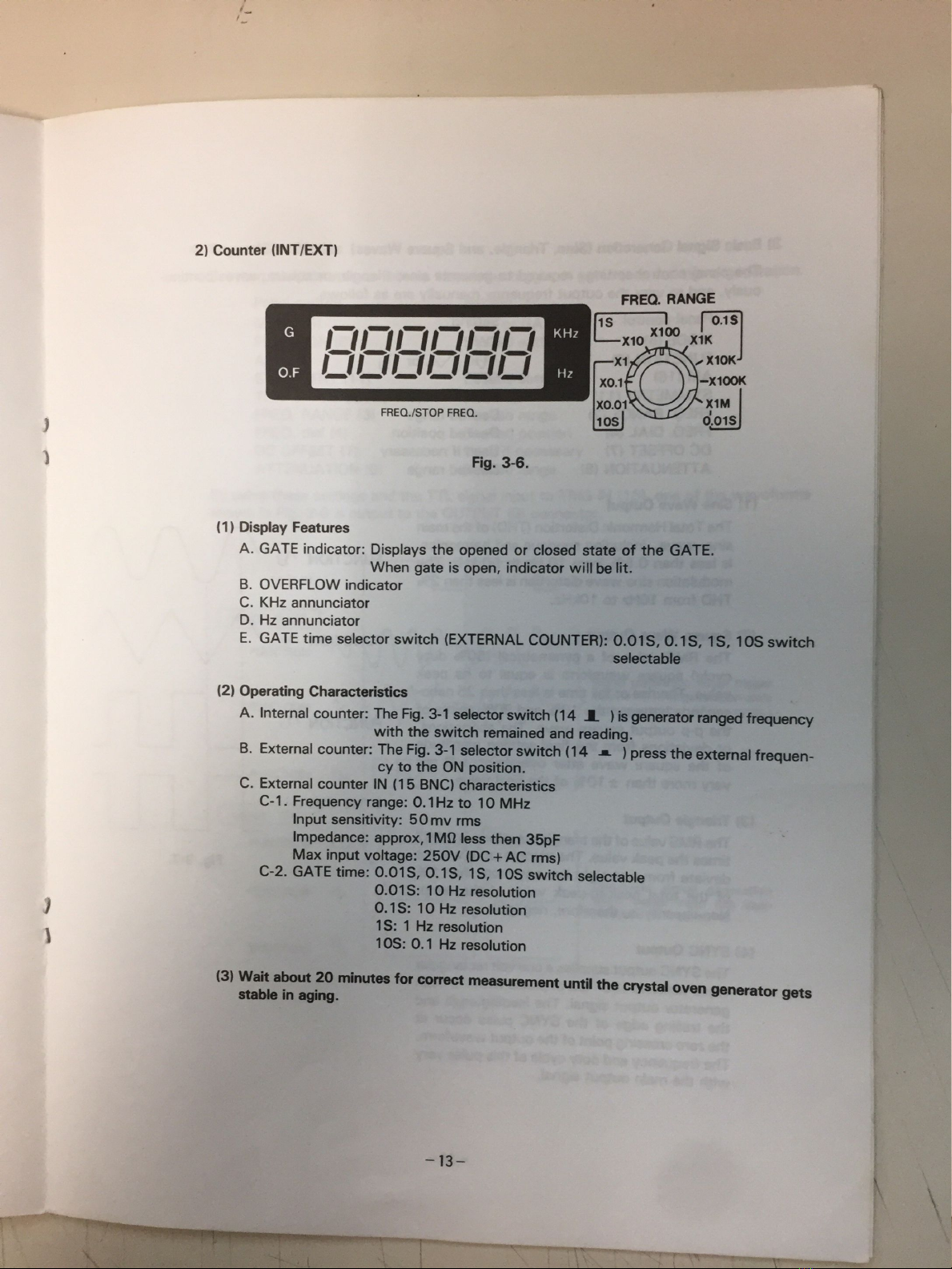
2)
Counter
(INT/EXT)
FREO.
RANGE
1
51K.0
1
S
G
x10
x100x
x1,
X13
OF
xo.
1'>-X100K
xo.
01‘\
XM
FREQJSTOP
FREO.
ws
6.015
Fig.
3-6.
(1)
Display
Features
A.
GATE
indicator:
Displays
the
opened
or
closed
state
of
the
GATE.
When
gate
is
open,
indicator
willbe
lit.
B.
OVERFLOW
indicator
C.
KHz
annunciator
D.
Hz
annunciator
E.
GATE
time
selector
switch
(EXTERNAL
COUNTER):
0.018,
0.1S,
IS,
106
switch
selectable
(Z)
Operating
Characteristics
A.
Internal
counter:
The
Fig.
3-1
selectorswitch
(14
J.
)is
generatorrangedfrequency
with
the
switch
remained
and
reading.
B
External
counter:
The
Fig.
3-1
selector
switch
(14
J.
)press
the
extemal
frequen-
cy
to
the
ON
position.
C.
External
counter
IN
(15
BNC)
characteristics
Gi.
Frequency
range:
0.1Hz
to
10
MHz
Input
sensitivity:
50mv
rms
lmpedance:
approx,1M9
less
then
35pF
Max
input
voltage:
250V
(DC+AC
rms)
C-2.
GATE
time:
0.018,
0.18,
1S,
108
switch
selectable
0.018:
10
Hz
resolution
0.1S:
10
Hz
resolution
1S:
1
Hz
resolution
108:
0.1
Hz
resolution
I3)Waitabout20'rnlnr.rtesforcorractmeasurementuntilthe
stal
in
cry
ovengeneratorgets
-13-
¿sum-j
i
h.“
“y”rw,
wav,“
las-H4!»
«es-Mew;
“"WWW'v-M,

gle,
and
Square
Waves)
.
sino,
triangle,
or
square
waves
continu-
ly
are
as
follows.
3)
Basic
Signal
Generation
(Sine,
Trian
The
panel
control
settings
required
to
general:l
ously,
and
to
very
the
output
frequency
man
Panel
control
zevzting
MODE
(5)
FUNCTION
(6)
NF,
N
mr
"Li
AM
(16)
OF
.
sea
SYMMETRY
(11)
Used
if
nace
ry
FRED.
RANGE
(2)
Desired
range
FREQ.
DiAL
(4)
Desired
posmon
DC
OFFSET
(7)
Used
if
necessary
ATTENUATION
(8)
Desired
range
(1)
Sine
Wave
Output
The
Total
Harrnonic
Distortion
(T
HD)
of
the
main
eine
wave,
including
spurious
and
harrnonics,
i
is
less
than
0.5%
from
10
Hz
to
50
kHz.
The
FUNCTION
{U
modulation
sine
wave
distortion
is
less
than
2%
THD
from
10Hz
to
10kHz.
v
(Z)
Square
Wave
Output
The
RMS
value
of
a
symmetrical
(50%
duty
cycle)
square
waveform
is
equal
to
its
peak
value.
The
rise
or
fall
time
is
less
than
25
nano-
seconds
between
the
10%
and
90%
points
of
the
pp
output
square
wave.
The
aberrations,
FUNCTION
FLI
or
deviations
from
the
final
settling
amplitude
of
the
square
wave
after
overshoot,
will
not
very
more
than
zi:
10%
of
the
final
value.
FUNCTION
’\/
I
l
I
l
l
I
I
l
l
l
I
I
i
i
I
l
l
I
i
(3)
Triangle
Output
SYNC
our
The
RMS
value
of
the
triangle
waveform
is
0.557
times
the
peak
value.
The
triangle
ramp
will
not
deviate
from
a
straight
line
any
more
than
1%
Fig.
all
of
the
total
peak-to-peak
value
of
the
ramp.
Non-linearity
is,
therefore,
negligible.
(4)
SYNC
Output
The
SYNC
output
supplies
a
one
volt
rectangular
wave
which
is
180°
out
of
phase
with
the
main
generator
output
signal.
The
leading
edge
and
the
tiailing
edge
of
the
SYNC
pulse
occur
at
the
zero
crossing
point
of
the
output
waveform.
The
frequency
and
duty
c
-
.
,
ycle
of
this
ulse
With
the
main
output
Signal.
P
very
-14‘

4)
Trigger/Gate
Modos
Set
the
panel
controls
as
fo||ows
to
use
the
trigger
or
gate
mode
for
signal
generation.
Panel
control
MODE
(S)
FUNCTION
(6)
AM
(16)
SYMMETRY
(1
1)
TRlG
START
LEVEL
(10)
FREQ.
RANGE
(3)
FRED.
dial
(4)
DC
OFFSET
(7)
ATTENUATION
(8)
Setting
TRlG
or
GATE
Desired
setting
OFF
Desired
setting
Index
up
Desired
range
Desired
position
Used
if
necessary
Desired
range
By
using
these
settings
and
the
TTL
signal
input
to
ING
IN
one
of
the
wavaforms
shown
in
Fig.
3-8
is
output
to
the
OUTPUT
(9)
connector.
TR|G
W
I
MODE:
GATE
E
’\/
FUNCTION
FUNCTION
’\/
FUNCTION
¡"LJ
MODE:
TRIG
FUNCTION
IV
l
g
l
FUNCT|0N
/\,
u
A
i
A
l
l
¡
|
I
l
I
l
Signal
geneiation
when
winner
inputisHl.
(Onegsnetauon'
más
atüiecompletimafonocyde.)
One-cycle
signal
generation
when
trigger
input
has
been
swnched
from
LO
to
Hi.
""WÏWW‘W
.,

e,
the
output
signal
frequency
range
from
0.1Hz
to
1MHz
and
ln
the
trigger
or
gate
mod
is
DC
to
100kHz.
trigger
input
frequency
range
(TRIG
START
LEVEL
contro|)
Fig.
3-8
shows
the
output
waveforms
obtained
the
middle.
The
TRlG
START
LEVEL
is
turned
to
a
TRIG
IN
l
Il
:
TRIG
START
LEVEL
.
¡\
l
\
7’
FUNCTION
¡b
É
o
MODE
me
o
M
O‘
FR).
3«9.
with
the
TRIG
START
LEVEL
noi
set
¡n
djust
the
level
to
start
signal
generation.
Fig.
3-10
shows
the
waveform
‘16-

Panel
contro|
Setting
MODE
(5)
BURST
FUNCTlON
(6)
r\,
.
N
,
or
rLu
AM
(16)
OFF
SYMMETRY
(1
1)
Pushed
in
FREQ.
RANGE
(3)
Desired
range
FREQ.
dia|
(4)
Desired
position
DC
OFFSET
(7)
Used
if
necessary
TRIG
START
LEVEL
(10)
Index
up
SET
START/SWEEP
(19)
SWEEP
(
J.
)
TlME
(21)
Desired
range
SYMMETRYNARIABLE
(23)
Desired
position
ATTENUATlON
(8)
Desired
range
SYMMETRY
(FULL
om
SWEEP/BURST
m
VAR'ABLE
GATE
om
©
É
E
:
SYMMETRY
knob
lil
'|ll
Ü
TI
=Tz
Burst
wave
output
¡V
UWVH
—.
Pull
and
turn
n.
mmm“
¡
.
‘,
Ü"
Ratio
Tun
is
ediusted.
|ll
ll
5
'n
VARIABLE
knob:
i
g
Il
Turn
clockwise
to
amm
'¡4————-—————'1
T
Rima)
becomes
shortsr,
Turn
counterclockwise
to
mcreese
T
(time).
Fig.
3-9
shows
an
output
burst
waveform.
The
trigger
start
level
can
be
‘
cha
the
same
procedure
es
in
Trigger/Gate
Modas.
nged
by
usnng
6)
SWEEP
Modo
The
sweep
mode
alloWs
a
linear
or
logarithmic
sweep
to
be
m
‘
._
.
ade
at
a
swee
1.100
in
a
specified
frequency
range.
The
sweep
time
can
be
set
from
1m.«:)tlt>at160:f
1
to
the
START/MOD
LEVEL
control
(20)
to
set
the
sweep
start
frequency
and
th
'
UZ”
(4)
to
set
the
sweep
end
frequency.
e
FREQ'
dm
The
panel
contro!
settings
for
the
sweep
mode
are
as
fo||ows.
-17-
"WM-J"
““WW
A
.M
.
-t
,..
a.
Í
2

The
panel
control
setting
used
to
output
DC
voltage
Panel
control
FUNCTION
(6)
FREO.
RANGE
(3)
DC
OFFSET
(7)
ATTENUATION
(8)
only
are
as
follows.
Setting
All
buttons
released
(Push
all
buttons
out.)
Range
of
x
100
or
less
Pull
the
knob
OdB
A
max.
of
:1OOCV
output
can
be
obtained
at
an
open
output
terminal
by
adjustirtg
the
DC
OFFSET
knob.
Because
the
output
impedance
is
set
to
SO
ohms,
the
relationshrp
bet-
ween
the
output
voltage
and
max.
load
current
is
as
shown
In
Fig.
3-15.
10
When
max.
output
is
10V.
9)
Amplitude
Modulation
DC
to
1MHz.
The
maximum
input
v
The
input
impedance
is
about
10
k
modulation
ara
as
fo||ows.
Panel
control
MODE
(5)
FUNCTION
AM
(16)
SYMMETRY
(1
1)
FREQ.
RANGE
(3)
FREO.
dial
(4)
DC
OFFSET
(7)
AM
CARRIER
LEVEL
(22)
MOD
LEVEL
(20)
100
Max.
load
current
(mA)
Fig.
3-15.
The
modulation
signal
frequency
ranges
from
oltage
required
for
full
(100%)
modulation
is
5Vp-p.
ohms.
The
control
panel
settings
used
for
amplitude
Pressed
Desired
range
Desired
position
Used
if
necessary
Desired
level
Desired
modulation
level
‘
20-
¿a

"EmaX'Eo
E
x
1
OO
=
percent
modulation
o
H
ll
_
:IlIHHHHHHHHHHHHHH
HHHHH
HHHHHHHHHHHHHHIIIHlunlIlIIHHHH
HHHHHHHHH
HHHH
HH
IHIII||""H“"""""H
H
HH
HH
mv
\
AVERAGE
AMPLITUDE
Fig.
3-16.
FULL
CARRIER
SUPPRESSED
CARRIER
Partially
Suppressed
0%
Modulation
Carrier
No
Modulation
HHHHHHHHHHHHHHHHHHE
lllllllllllllllllll
Fully
Suppressed
.
Carrier
50%
Modulation
No
Modulation
CD
M
Unsuppressed
Carrier
with
Modulation
100%
Modulation
m
Partially
Suppressed
Carrier
with
Same
Modulation
Ovarmodulation
WWW
Fully
Suppressed
Carrier
with
Same
Modulation
Modulation
=
B +
A
or
¿B-
2
A
Fig.
3-17.
AM
modulation
and
suppressed
carrier
waveforms.
If
the
AM
CARRIER
LEVEL
(22)
is
turned
around
the
middle
a
double
sideband
with
a
suppressed
carrier
is
obtained.
HHHHHHHHHHHHHH
'H‘HHHHHHHHHHHH
"“HHHHHHH
Barbie-sideband
output
waveform
Fig.
3-13.
-21-
.c
A,
-W._...__,._«._.__r..
MW}
Table of contents
Other PRO-TEK Measuring Instrument manuals

PRO-TEK
PRO-TEK A334M User manual

PRO-TEK
PRO-TEK 3290N User manual

PRO-TEK
PRO-TEK Z9216 User manual

PRO-TEK
PRO-TEK WI Series User manual

PRO-TEK
PRO-TEK A734 User manual

PRO-TEK
PRO-TEK A734 User manual

PRO-TEK
PRO-TEK 1006 User manual

PRO-TEK
PRO-TEK 9216A User manual

PRO-TEK
PRO-TEK 3201 User manual

PRO-TEK
PRO-TEK A434L User manual

Popular Measuring Instrument manuals by other brands

Rohde & Schwarz
Rohde & Schwarz R&SHMC8012 user manual

Precision Digital Corporation
Precision Digital Corporation ProtEX-MAX PD8-6100 instruction manual

Hastings
Hastings 6600 Operating and maintenance manual

Hach
Hach CM130 user manual

Metrohm
Metrohm 757 VA Computrace Hardware manual

Measurlogic
Measurlogic DTS 310 quick start guide


