PRO-TEK 9216A User manual


PROTEK 9216A
Digital LCR Meter
User’s Manual
Volume1: BasicOperation Rev.3.0

2
Table of contents
Introduction...........................................................................................................................................................4
Warranty.........................................................................................................................................................4
General Safety Summary..............................................................................................................................5
Preventing Injury.....................................................................................................................................5
Preventing Instrument Damage..............................................................................................................5
Maintenance, Repair, and Storage...................................................................................................5
Product Damage Prevention............................................................................................................6
Line Voltage Requirements..............................................................................................................6
Fuse Requirements..........................................................................................................................6
Conventions Used in This Manual .................................................................................................................7
Safety Terms...........................................................................................................................................7
Product Familiarization.........................................................................................................................................8
Front Panel Components...............................................................................................................................8
Fixture Inputs...........................................................................................................................................8
Measurement Modes and the Mode Selection Keys...............................................................................9
Alphanumeric Displays and Parameter Indicators..................................................................................9
Programming and Operator Interface Keys..........................................................................................10
Rear Panel Components..............................................................................................................................12
Specifications...............................................................................................................................................13
Display...................................................................................................................................................13
Test Conditions......................................................................................................................................13
Accuracy................................................................................................................................................13
Features and Options...................................................................................................................................14
General Features...................................................................................................................................14
Options..................................................................................................................................................15
Basic Operations.................................................................................................................................................16
Operation of the LCR Meter For the First Time...........................................................................................16
Unpacking and Inspection.....................................................................................................................16
Installation .............................................................................................................................................16
Startup Procedures......................................................................................................................................17
Before Applying Power..........................................................................................................................17
Before Using the Test Fixture................................................................................................................17
Fixture Options...............................................................................................................................17
Null Calibration Procedure..............................................................................................................18
Changing Test Setup Parameter Settings....................................................................................................18

3
.
.
.
.
.
.
.
.
.
Default Setup.........................................................................................................................................19
Changing, Storing, and Recalling Custom Setups................................................................................20
Measurement Mode........................................................................................................................20
Frequency.......................................................................................................................................20
Drive Voltage..................................................................................................................................21
Bias.................................................................................................................................................22
Measurement Rate.........................................................................................................................24
Settling Time..................................................................................................................................25
Triggering........................................................................................................................................25
Store and Recall.............................................................................................................................26
Range.............................................................................................................................................26
Series and Parallel Equivalent Circuits..........................................................................................29
Display Types.................................................................................................................................29

4
Introduction
ImportantBackgroundInformation
The PROTEK 9216A DIGITAL LCR Meter is a high quality instrument that gives you
many years of good service. Please read the information in this chapter before using or
applying power to the meter. Information on operating and using the meter is given in
the following chapters.
Warranty
PROTEK warrants that this product will be free from defects in materials and
workmanship for a period of one year from the date of purchase. If any such product
proves defective during this warranty period, PROTEK, at its option, either will repair the
defective product without charge for parts and labor, or will provide a replacement in
exchange for the defective product.
In order to obtain service under this warranty, the customer must notify PROTEK of
the defect before the expiration of the warranty period and make suitable arrangements
for the performance of service. The customer shall be responsible for packaging and
shipping the defective product to the service center designated by PROTEK, with
shipping charges prepaid. PROTEK shall pay for the return of the product to customer if
the shipment is to a location within the country in which the PROTEK service center is
located. The customer shall be responsible or paying all shipping charges, duties, taxes,
and any other charges forproducts returned to any other locations.
This warranty shall not apply to any defect, failure or damage caused by improper
use or improper or inadequate maintenance and care. PROTEK shall not be obligated
to furnish service under this warranty:
To repair damage resulting from attempts by personnel other than PROTEK repre-
sentatives to install, repair or service the product;
To repair damage resulting from improper use or connection to incompatible
equipment; or
To service a product that has been modified or integrated with other products when
the effect of such modification or integration increases the time or difficulty of
servicing the product.
This warranty is given by PROTEK with respect to this product in lieu of any other
warranties, expressed or implied. PROTEK and its vendors disclaim any implied
warranties of merchantability or fitness for a particular purpose.
Chapter
1

5
.
.
.
.
.
.
.
.
.
PROTEK’s responsibility to repair or replace defective products is the sole and
exclusive remedy provided to the customer for breach of this warranty. PROTEK
and its vendors will not be liable for any indirect, special, incidental, or
consequential damages irrespective of whether PROTEK or the vendor has
advance notice of the possibility of such damages.
General Safety Summary
Review the following safety precautions to avoid injury and prevent damage to this
product or any products connected to it.
NOTE: Only qualified personnel should perform service procedures.
Preventing Injury
Use Proper Power Cord. To avoid fire hazard, use only the power cord specified for this
product.
Avoid Electrical Overload. To avoid electric shock or fire hazard, do not apply a voltage
to a terminal this is outside the range specified for that terminal.
Ground the Product. This product is grounded through the grounding conductor of the
power cord. To avoid electric shock, the grounding conductor must be connected to
earth ground. Before making connections to the input or output terminal of the product,
ensure that the product is properly grounded.
Do Not Operate Without Cover. To avoid electric shock or fire hazard, do not operate
this product with covers or panels removed.
Use Proper Fuse. To avoid fire hazard, use only the fuse type and rating specified for
this product.
Do Not Operate in Wet/Damp Conditions. To avoid electric shock, do not operate this
product in damp or wet conditions.
Do Not Operate in an explosive atmosphere. To avoid injury or fire hazard, do not
operate this product in an explosive atmosphere.
Keep Probe Surface clean. To avoid electric shock and erroneous readings, keep the
probe surface clean.
Preventing Instrument Damage
Maintenance, Repair, and Storage
This equipment is composed of many high-precision components and components
which require high internal pressure. Care is required when handling or storing this
equipment.
Occasionally, if the surface of the panel is dirty, rub the affected area lightly with a
soft cloth soaked in a light neutral detergent or alcohol. Never use highly volatile
material such as benzene or paint thinner.
The ideal ambient temperature range for storing this equipment is 10C to 60C
(14F to 140F).

6
To avoid personal injury, do not remove the product covers. Do not operate the
product without the covers properly installed.
Two spare fuses are shipped with this equipment.
In order to maintain this equipment in a stable and efficient operating condition,
calibrate the equipment after every 1,000 hours operating time or every 6 months,
whichever is shorter.
Product Damage Prevention
Use Proper Power Source. Do not operate this product from a power source that
applies more than the voltage specified.
Provide Proper Ventilation. To prevent product overheating, provide proper ventilation.
Do Not Operate With Suspected Failures. If you suspect there is damage to this
product, have it Suspected Failures inspected by qualified service personnel.
Do not immerse in Liquids Clean the probe using only a damp cloth. Refer to the
cleaning instructions.
Line Voltage Requirements
Refer to the following table for the correct operating voltage ranges for this LCR meter.
Check the line voltage prior to connecting to the power source, and verify that it is within
a voltage range listed below.
Rating
Operating Voltage Range
AC 115 V
AC 98 V–132 V
AC 230 V
AC 196–253 V
If the LCR meter is to be used at a voltage other than 230V AC, the operating voltage
may be changed by the following procedure ·
Remove the power cable from AC input.
Insert a flat-bladed screwdriver into the slot located on right side of the fuse holder
cap; remove the cap by pressing and then pulling up the screwdriver.
Rotate the cap on the fuse holder to set the voltage to the desired level.
Connect power cable to the AC input.
If a voltage below AC 115 V is required, the power cable and fuse may need to be
changed. In such case, contract your nearest dealer for appropriate service.
After use, disconnect the equipment from the AC outlet.
Fuse Requirements
In order to prevent circuit damage resulting from over current, use the correct fuse value.
The fuse ratings are as follows.

7
.
.
.
.
.
.
.
.
.
Circuit No.
Shape (diameter length) mm
Rating
Remarks
F1101
5.2 20
250 V T500 mA
For AC l15V
250 V T250 mA
For AC 230 V
F601
5.2 20
250 V F250 mA
The internal fuse rating is as follows:
Circuit No.
Shape (diameter length) mm
Rating
Remarks
F602
5.2 20
250 V F250 mA
Note: Refer to the section on troubleshooting in the Reference Manual for instructions
on replacement of the internal fuse.
Conventions Used in This Manual
In this manual, you will find various procedures, which contain steps of instructions
for you to perform. To keep these instructions clear and consistent, this manual
uses the following conventions:
Operating procedures and names of front panel controls are in uppercase and
boldface print.
The case of each name used in the manual is the same (Initial Capitals or
UPPERCASE) as that used on the instrument itself.
Instruction steps are numbered (1, 2, 3, ), unless there is only one step.
When steps require that you make a sequence of selections using front panel
controls and keys, an arrow () is used in the text to indicate an LED result when a
front panel entry is made. Also, whether a name is a key or LED display reading is
clearly indicated:
Example: Press DISP (Entry) ENTER
Safety Terms
The following terms are also used in this manual:
WARNING identifies conditions or practices that could result in injury.
CAUTION identifies conditions or practices that could result in damage to this
product or other property.
NOTICE identifies conditions or practices that could result in incorrect test
data.

8
Product Familiarization
DescriptionoftheLCRMeterandItsFeatures
In this chapter, the controls and connections of the LCR Meter are described, and its
basic operation is summarized in terms of the meter’s specifications, features and options,
and operating modes.
Front Panel Components
The front panel and its displays, controls, and connections are shown in the following
illustration:
Test Frequency Measurement Rate
Bias
Test Voltage Display option Back space
Measurement modeFixture inputs Trigger
Setup Key pad Enter
First, the displays, controls, and connections on the left side of the front panel are ex-
plained, and thenthe many buttons and keysonthe right side are described.
Fixture Inputs
The input terminals labeled IL, PL, PH, and IH connect the test fixture or adapter to the
instrument, as discussed in the section in Chapter 3 on “Connecting a Component.” Two
of the terminals provide a current source to the component under test, and the other two
terminals provide a high impedance connection to measure the voltage across the device.
This four-wire or “Kelvin” type of measurement setup is designed to increase accuracy by
reducing the amount of current in the voltage-sensing wires. Warning: Do not connect
any active voltage source to these terminals, especially high voltages.
Measurement Modes and the Mode Selection Keys
These keys select the measurement to make on the component under test. One of five
measurement modes may be selected: Auto, R+Q, L+Q, C+D or C+R. The selected
Chapter
2

9
mode is indicated by LEDs above the alphanumeric displays. The operation of each
mode can be explained as follows:
AUTO In this mode, the meter automatically selects the most appropriate
measurement on the device. The selection is made according to the following
criteria:
If |Q| < 0.125, the meter selects the R+Q measurement mode.
If Q > +0.125, the meter selects the L+Q measurement mode.
If Q < 0.125 and the meter is in the series equivalent circuit mode, the C+R
measurement mode is selected.
If Q < 0.125 and the meter is in the parallel equivalent circuit mode, the C+D
measurement mode is selected.
R+Q In this mode, resistance is displayed on the main parameter display
and the Q (quality factor) is displayed on the secondary parameter display. The R-
value is either the series or parallel equivalent resistance of the component under test.
The unit for R is , k, or M. The Q value is the dimensionless ratio of the
imaginary part of the component’s impedance to its real part. If Q has a positive (+)
value, the reactive component of the device under test is inductive. If Q has a
negative () value, it is capacitive.
L+Q In this mode, the series or parallel equivalent inductance value of a
component under test is displayed on the main parameter display units in units of µH,
mH, or H, and its dimensionless Q value is displayed on the secondary parameter
display.
C+D In this mode, the series or parallel equivalent capacitance value of a
component under test is displayed on the main parameter display in units of pF, nF,
or µF. On the secondary parameter display, the dimensionless ratio D 1/Q is given.
D is normally a smallvaluefora good capacitor.
C+R In this mode, the capacitance is displayed on the main parameter
display and the equivalent resistance is displayed on the secondary parameter
display. The unitfor resistance is unless the kindicator LED is lit.
Alphanumeric Displays and Parameter Indicators
The two 5-digit (plus sign) LED
1
-segmented alphanumeric displays provide measurement
results, entered parameter values, and status messages. The left display gives the value
of the main parameter of the component under test (L, R, C) and the right display gives
the value of its secondary parameter (Q,D, R, %). Above and next to these two
alphanumeric displays are various LEDs that, when lit, indicate something about the
measurement:
1
LED = light-emitting diode

10
AUTO, R L, C, % LEDsthat indicate the measurement type forthe main parameter
Q, D,R, % LEDs that indicate the measurement type for the secondary
parameter
, k, MLEDs indicating the unitsof the value being displayed on the left
µH, mH, H
pF, nF, F
kThe right-side display is dimensionless or has units of ohms
unless thisLEDis on.
REM, ACT, ERR These LEDs give information on the status of the remote control
(computer) interface operations.
REM: Indicates that the display is being controlled remotely via the interface
connector on the rear panel.
ACT: Indicates that the remote control interface isactive.
ERR: Indicatesthat a remote command contained an error.
NOM, LIM, LIM Indicates which Binning
2
parameter is being entered
Programming and Operator Interface Keys
On the right side of the front panel of theLCR meter, there are many buttons and keys for
programming test conditions and for general operator interface. These keys are grouped
according to function, and some groups have LED indicators associated with them show
which option has been selected.
Frequency The 9216A has five selectable fixed frequencies with an accuracy to
100ppm (0.01%). 100Hz, 120Hz, 1kHz, 10kHz or 100 kHz may be selected by
pressing the up/down keys on the front panel keypad until its corresponding LED is
illuminated.
Drive Voltage
VOLT Pressing the VOLT key, the output voltage will cycle through three
fixed output drive voltages (0.1V, 0.25V, 1.0V). An LED indicates the selected
drive voltage. If NO LED is lit, then the output drive voltage is in the vernier
mode.
CONS This key sets the meterto the constant voltage mode.
BIAS Thebias mode isused onlyfor capacitance measurements. Pressing
these keys for any other measurement will generate the “bias for c” error message.
INT Selects a 2.0 VDC internal bias.
EXT Selects a voltage from an external source to be applied to the
capacitor under test.
2
Binning is explainedlater.

11
MEAS RATE Selects the measuring rate. At frequencies of 1 kHz or greater, slow
(2 measurements per second), medium (10 measurements per second, and fast
measurements (20 measurements per seconds) may be selected.
DISPLAY
Average The average of 2 to 20 measurement readings will be displayed.
The numberof measurements in the average is selected fromthe keypad.
HOLD This key holds the meter in its current measurement range. Pressing
the hold key a second time returns the meter to the Auto-Range mode. A
specific range mayalso be entered from the numeric keys on the keypad.
EQU This key toggles the equivalent circuit for the component under test
between a series or parallel circuit.
DISP The DISP key cycles through the display parameters that may be
selected. The display parameters that may be selected are:
VALUE The measured value of the device under test is displayed.
DEV The deviation from a value previously entered is displayed.
% DEV The percent deviation from a previously entered value is
displayed.
ENTRY Usedfor entering parameter values.
BINS Selectsthe bin number when Binning is enabled.
Note: Certain displays are not available unless data has been entered. For example,
DEV and % DEV are not available unless a nominal value has already been entered.
Also, BINS is notavailable unlessbinning data has previously been entered.
Backspace key used for correcting mistakes when entering
numeric data. This key also serves as the “Local” function.
[0]...[9] These keys are used to enter parameters and are only active
when the meter is in the ENTRY mode.
ENTER [, µH, pF], [k, mH, n F], [M, H, µF]. These three keys are
used for entering numeric parameters in the entry mode (e.g. R, L, C
values). The bottom-most key (M, H, µF) may be used as a general
entry key for entering parameters not listed on the keypad, such as
percent %.
SETUP
STO, RCL The 9216A can store up to nine setups in the memory. To
store the present configuration in memory location #n, press STO [n]
ENTER. To recall a setup, press RCL [n] CAL ENTER.
CAL Enables a series of internal calibration routines, including
open/short and settling time calibration, output amplitude drive, and
internal self-tests.
BIN#, NOM, LIM These keys are used to enter Binning parameters.
The BINNING LED is on when Binning is enabled and the optional
handler is active.

12
TRIGGER
MODE This key toggles between continuous (CONT) or TRIGGERED
measurements .
TRIG When TRIGGER mode is selected, measurements are initiated when this
key is pressed or by the handler or computer interfaces. The TRIG LED will flash
when this mode is enabled.
Rear Panel Components
The rearpanel and its controls and connections are shown in thefollowing illustration:
[1] AC POWER CONNECTOR The AC power cord is inserted into this connector. The
fuse and line voltage selectorare located in the connectorhousing.
[2] POWER SWITCH Turns the meter on and off.
[3] EXTERNAL BIAS INPUT Two banana plugs are used to input an external bias
voltage. The bias supply voltage must be floating and well filtered. Neither input
connector can be referenced to ground.
[4] EXTERNAL BIAS FUSE Protects external bias circuit from currents greater than 250
mA.
[5] RS232 DB25 This connector allows the meter to communicate as a DCE (data
communications equipment, e. g. a modem) to a DTE (data terminal equipment, e.g.,
a computer) using the RS-232C protocol. For further information, refer to the
material on remote programming inthe Reference Manual.
[6] SW1 The switches set the RS232C protocol parameters. The Baud rate, word
length and parity may be set.

13
Specifications
Display
Measurement Modes: Auto, R+Q, L+Q, C+D, C+R
Equivalent Circuit: Series or Parallel
Parameters Displayed: Value, Deviation, % Deviation or Bin Number. Deviation
and % deviation are calculated from a stored relative value
Averaging: 2–10 Measurements
Measurement Range: R+Q: R: 0.0001–2000 M
Q: 0.00001–50
L+Q: L: 0.0001 µH–99999 H
Q: 0.00001–50
C+D: C: 0.0001 pF–99999 µF
D: 0.00001–10
C+R: C: 0.0001 pF–99999 µF
R: 0.00001–99999 k
Test Conditions
Test Frequency: 100 Hz, 120 Hz, 1 kHz, 10 kHz, 100 kHz
Frequency accuracy: ±100ppm.
Drive Voltage: Preset Levels: 0.10, 0.25, and 1.0 Vrms.
Vernier: 0.1 to 1.0 Vrms with 50 mV resolution.
Drive level accuracy: ±2%.
Measurement Rates: (a) Slow(2 meas./sec.), Medium (10 meas./sec.), orFast
(20 meas./sec.) for test frequencies of 1 kHz and above.
(b) Approx. 0.6, 2.4, or 6 measurements per second at
100 Hz and120 Hz.
Ranging Auto or Manual
Triggering Continuous, Manual, or Remote over RS232 or
Handler Interface
Bias Voltage Internal: 2.0 VDC ±2%
External: 0 to +40 VDC (fused @ 0.25 A)
Accuracy
Conditions: Allow 30 minutes of warmup before measurements; all accuracies are at
23°C (73F) ±5°C
Basicaccuracy0.05%. Refer to the accuracy section in the Reference Manual for
detailed specifications.
The following summarizes typical accuracy specifications:

14
Accuracy Value
better than 1% for R > 0.125 and R < 16 M
L > 2.5 H and L < 25 kH
C > 1.25 pF and C < 12.8 mF
better than 5 % for R > 21 mand R < 96 M
L > 420 nHand L <l50 kH
C > 0.21 pF and C < 77 mF
at the following conditions:
1.0V, 0.5V, or 0.25V output voltage
Slowor medium measurement speed
Q and D < 0.1 for R and C
Q > 10 for L
100Hz, 120Hz or 1 KHz test frequency for R
100 Hz test frequency for Lmax and Cmax
10 KHz test frequency for Lmin and Cmin
Features and Options
General Features
Feature
Specification
Fixture
4-wire Kelvin fixture for parts with radialand axial leads
Protection
Protected up to 1 Joule of stored energy, 200 V DC for charged capacitors;
fusedat 0.25 A output currentfor biased measurement
Zeroing
Open and short circuit compensation. Compensation Limits: short circuit:
R<20, Z<50, open circuit: Z>10k
Binning
Up to 8 Pass Bins, QDR and General Fail Bins, all defined by the front panel or
computer interface. Binning setups may be stored in nonvolatile memory
Self Test
Tests the ROM, CPU, nonvolatile RAM, clock generator, A/D converter,
internal bias, multiplier, output drive circuitry, gain circuitry, and source
resistances.
Store and Recall
memory
Stores and recalls nine complete instrument setups. Recall 0 recalls the default
setup.
RS232 Interface
All instrument functions can be controlled or read over the interface.
Operating Conditions
0 to 50°C at a relative humidity of 0 to 80%
Power
20 Watts, 110/220 VA, 50/60 Hz
Dimensions
4 ¼ " H 14 ¼ " W 15" D
Weight:
12 ¾ lbs
Warranty
Two year parts and labor on materials and workmanship

15
Options
Feature
Specification
IEE-488 interface
Instrument functions can be controlled and read over this interface
Handler/sorter interface
DB male connector provides the signal linesforbinning, instrument
status and input trigger.
Note: option consists of both interfaces
Kelvin clips
Provides connection to devices that are not easily accommodated by the
test fixture. Polarity is indicated for biased measurements.
SMD Tweezers
Provides connection to surface mount components
BNC fixture adapter
Connects remote fixtures or devices to the 9216A

16
Basic Operations
Howthe9216AOperatesandWhatItCanDo
The 9216A LCR meter is very versatile in that the user can customize the
measurement and operating modes to obtain the best results in a particular
situation. In this chapter, the basics of the meter’s operation are summarized.
Operation of the LCR Meter For the First Time
Before using 9216A LCR Meter, ensure that it is properly installed, and powered
on.
To get the maximum accuracy for your most critical measurements you
should know how to select the various options and to set up the test conditions
and the proper use of the test fixture you have chosen to use with your meter.
Unpacking and Inspection
After unpacking the 9216A LCR Meter, verify that all parts are included and have
not been damaged during transportation. Retain the packing materials.
Packing Contents:
9216A LCR Meter
Radial Fixture
Power Cord
User Manuals
Installation
To properly installand poweronthe meter, perform the following steps:
Be sure you have the appropriate operating environment.
Leave a space of at least 5.1 cm (2 in) on each side of the meter for proper
ventilation.
Check the fuse for proper type and rating.
Checkfor proper electricalconnections.
Connect theproper powercord to thepower connector on the rear panel.
Chapter
3

17
Startup Procedures
When turned on, the meter will first enter the self-test mode and perform the
following procedure: first, it will display the program version “0X” and the model
number “HC9216” for about three seconds. Next, the meter will display “test” and
“…..” while it performs the self-test. If all tests are successful, “test pass” will be
displayed as a result. In order for the self-test to operate correctly, it is important
to followcertain startup procedures.
Before Applying Power
Prior to turning the unit on, be sure there are no components in the input fixture.
Components in the fixture will cause the self-test to fail and display an error code.
Before Using the Test Fixture
When the self-test is completed, “over range” will be displayed, and the user can
proceed to set up the test conditions and to make measurements. For maximum
accuracy, however, a “null calibration” of the test fixtures needs to be performed
before taking any measurements.
Fixture Options
On the frontpanelof the instrument there are four BNC connectorsdesignated IL,
PL, PH, IH. In what is known as a “4-wire Kelvin connection,” two of these
terminals provide current to and from the device under test, and two of the
terminals sense the potential (voltage) across the device. Separate wires are
used for sensing thevoltage so to minimize the effect of the current in the sensing
wires inside the meter and to minimize stray impedance that can cause
measurement errors.
There are several fixtures available for special measurements: Radial fixture
(standard), Kelvin clips, SMD tweezers, and BNC adapter. The optional fixtures
may be purchased through our distributors.
The standard 9216A test fixture attaches to the four input terminals on the front
panel of the meter and provides two polarized, spring-loaded connection slots to
secure radial-leaded components under test while they are being measured. The
fixture also accommodates axial-leaded components whose leads are bent to
enable insertion into the fixture. Most components will plug into this test fixture,
therebyeliminating the need for special fixtures.

18
Null Calibration Procedure
Whenever the test configuration is changed, including a change of the fixture,
open and short circuit “null” calibrations should be made prior to taking
measurements to compensate for stray impedances, such as component lead
impedance, andfixture, cable and other stray capacitance. Null calibration should
be performed after any change in fixture configuration or for changes in the drive
amplitude. This calibration corrects for all frequencies and all ranges-it is not
necessary to re-calibrate for changes in frequency. For critical measurements,
null calibration should be performed frequently at some interval during the course
of measurements.
The LCR meter store open and short circuit calibration data in nonvolatile
memory. These data values are stored with the STO key and recalled using the
RCL key, allowing null calibration data to be saved for different fixtures.
The null calibration procedure is on the menu that is invoked by pressing the
CAL (Calibrate) key in the SETUP group of keys on the front panel of the meter.
To perform a null calibration, press the CAL key until the message “nuLL cAL”
appears on the alphanumeric display. Pressing the ENTER key while this
message is being displayed causes the message to change to “Short cAL.”
The short-circuit null calibration is done by placing a wire in the fixture
(thereby shorting the fixture’s terminals) that is between 26 to 16 AWG (0.02" to
0.05" or 0.51 to 1.30 mm dia.). The calibration proceeds automatically after the
user presses the ENTER key and moves hands and any miscellaneous objects
away from the fixture. When the short circuit calibration is finished, the meter
prompts the user for the next operation by displaying the message “oPEn cAL.”
To perform the open-circuit null calibration, remove the shorting wire, press
ENTER and again move hands away from the fixture. When the unithas finished,
it displays the message “cAL donE.” To dismiss this message and return to a
normal display mode, press the DISP (Display) key.
Changing Test Setup Parameter Settings
When powered on, the 9216A LCR Meter initially uses the default test setup
parameters, which include selection of the automatic (AUTO) measurement
mode, and the result of the measurement is displayed on the alphanumeric
readout. For most measurements, the test conditions in the automatic mode are
sufficient. However, by pressing the parameter keys on the front panel, the user
may enter customized test setup parameter selections, and by pressing the
keypad keys, enter the desired values of test parameters. Test parameters that
are not associated with dedicated keys on the front panel or keypad, such as the
number of measurementsbeing averaged, deviationmeasurements, etc., may be
entered by pressing the DISP key to enter the ENTRY mode. Table 3-1 below
shows appropriate settings for typical component values.

19
Table 3-1 Test Setup Parameter Settings for Typical Component Values.
Component
Value
Meas. Mode
Equiv. Circuit
Frequency
Unknown
Any
AUTO
Series
1 kHz
Resistor
< 1 k
> 1 k
R+Q
Series
1 kHz
100 or 120 Hz
Inductor
< 10 H
10 H–1 mH
1 mH–1H
> 1H
L+Q
Series
100 kHz
10 kHz
1 kHz
100 or 120 Hz
Capacitor
< 10 pF
10 pF–400 pF
400 pF–1 F
> 1 F
C+D
C+D
C+D
C+R or C+D
Parallel
Series or parallel
Series
Series
10 kHz
10 kHz
1 kHz
100 or 120 Hz
Default Setup
Holding down the backspace key () key while turning on the power to the meter
causes the meter to have the default setup values as listed in the table below.
Note: Alluser calibration settings and values will be lost.
To prevent the user calibration settings from being destroyed, after turning on
the meter without pressing the backspace key,press RCL [0] ENTER. This
key sequence will reset the meter to the default settings listed in the table below
without affecting user-entered calibration values. See the sections that follow for
more details on the settings listed in the table below.
Table 1-1: 9216A default settings
Setting
Value
Parameter
AUTO
Frequency
1KHz
Drive Voltage
1.0Vrms.
Bias
OFF
Measurement Rate
SLOW
Averaging
OFF
Range Hold
OFF
Equivalent Circuit
SERIES
Display
VALUE
Trigger Mode
CONT
Binning
OFF
Table of contents
Other PRO-TEK Measuring Instrument manuals
PRO-TEK
PRO-TEK B-810 User manual

PRO-TEK
PRO-TEK A734 User manual
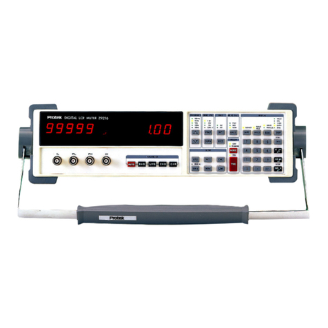
PRO-TEK
PRO-TEK Z9216 User manual
PRO-TEK
PRO-TEK A434L User manual

PRO-TEK
PRO-TEK A734 User manual

PRO-TEK
PRO-TEK 3201 User manual
PRO-TEK
PRO-TEK 1006 User manual
PRO-TEK
PRO-TEK WI Series User manual
PRO-TEK
PRO-TEK 3290N User manual
PRO-TEK
PRO-TEK B8000FD Series User manual
Popular Measuring Instrument manuals by other brands
Seaward
Seaward Solar Survey 200R manual
Honeywell
Honeywell Touchpoint Plus quick start guide

Siemens
Siemens SIPROCESS GA700 Compact operating instructions
Dwyer Instruments
Dwyer Instruments DDM-01 Installation and operating instructions

QUINN
QUINN 57460 Owner's manual & safety instructions
Keysight
Keysight M9602A PXIe Startup guide
