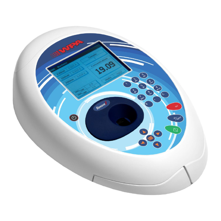
biochrom WPA Lightwave S2000 User manual

Issue 02 02/2004 English,S2000
Instruction Manual
Lightwave S2000
UV/Vis Diode Array Spectrophotometer
Biochrom Ltd
22 Cambridge Science Park
Milton Road
Cambridge
CB4 0FJ, UK
Tel: +44 (0) 1223 423723
Fax: +44 (0) 1223 420164
E-mail: enquires@biochrom.co.uk
Website: www.wpa.co.uk

Lightwave UV/Vis Diode Array Spectrophotometer
2
Declaration of Conformity
This is to certify that the WPA Lightwave S2000: 80-3000-72
manufactured by Biochrom Ltd. conform to the requirements of the following
Directives-: 73/23/EEC & 89/336/EEC
Standards to which conformity is declared
EN 61 010-1: 2001
Safety requirements for electrical equipment for measurement, control and
laboratory use.
EN 61326: 1998
Electrical equipment for measurement, control and laboratory use – EMC
requirements
Signed: Dated: 14th January 2003
David Parr
Managing Director
Biochrom Ltd
Postal address Telephone Telefax
Biochrom Ltd +44 1223 423723 +44 1223 420164
22 Cambridge Science Park
Milton Road e mail: enquiries@biochrom.co.uk website: http://www.biochrom.co.uk
Cambridge CB4 0FJ
England
Registered in England No: 974213
Registered Office: 22 Cambridge Science Park, Milton Road, Cambridge CB4 4FJ, England.

Lightwave UV/Vis Diode Array Spectrophotometer
3
TABLE OF CONTENTS
1 INTRODUCTION..........................................................................................................4
2 CONDITIONS OF SERVICE.........................................................................................4
3 PRINCIPLE OF OPERATION ......................................................................................5
4 SPECIFICATIONS .......................................................................................................6
5 CONTROLS.................................................................................................................7
6 CUVETTE CHAMBER..................................................................................................8
7 INSTALLATION & START-UP.....................................................................................9
8 MEASUREMENT OF CELL DENSITY....................................................................... 11
9 GENERAL OPERATIONS..........................................................................................12
9.1 REFERENCING ..........................................................................................................12
9.2 MEASUREMENT AT LOW LEVELS (<0.050A).................................................................12
10 SOFTWARE OPERATION.........................................................................................13
10.1 REPEAT LAST OPERATION .....................................................................................13
10.2 MAKE A MEASUREMENT .........................................................................................13
10.3 SINGLE/MULTI λ...................................................................................................13
10.3.1 Single measurement.......................................................................................14
10.3.2 Multi Wavelength............................................................................................14
10.4 CELL DENSITY/RATIO............................................................................................ 15
10.4.1 Cell Density Measurement..............................................................................15
10.4.2 Ratio Measurement........................................................................................16
10.5 SCANNING ...........................................................................................................16
10.6 SELECT A METHOD (TO “RUN A METHOD”SEE LATER IN MANUAL) ................................17
10.7 TO PROGRAM A NEW METHOD (OR RE-PROGRAM AN EXISTING METHOD).....................18
10.8 RUN A METHOD....................................................................................................24
10.9 USING BI-DIRECTIONAL COMMUNICATIONS ...............................................................25
11 INSTRUMENT SET-UP..............................................................................................25
11.1 COMMUNICATIONS ................................................................................................25
11.1.1 Printing...........................................................................................................26
11.1.2 Connection to PC...........................................................................................28
11.2 SETTING UP THE LIGHTWAVE TO A PCLINK.............................................................28
11.3 SET TIME/DATE....................................................................................................35
11.4 AUTO-PRINT ........................................................................................................35
12 SERVICING AND MAINTENANCE.............................................................................36
12.1 REPLACING THE LAMPS .........................................................................................36
12.2 ROUTINE MAINTENANCE........................................................................................37
12.3 DECONTAMINATION...............................................................................................37
12.4 CALIBRATION........................................................................................................37
13 CE MARKING ............................................................................................................ 38
14 GUARANTEE............................................................................................................. 38
15 HEALTH & SAFETY CERTIFICATE AND DECLARATION OF DECONTAMINATION
STATUS............................................................................................................................. 39

Lightwave UV/Vis Diode Array Spectrophotometer
4
1 Introduction
The Lightwave represents a breakthrough in UV/Vis Spectroscopy. For the
first time, the benefits of Diode Array technology have been incorporated into
a low cost Spectrophotometer.
The Lightwave offers: -
•Instantaneous scanning
•No moving parts
•Open sample compartment
•Space saving shape
We believe that the Lightwave will give many years of trouble free operation.
We do however recommend that you read this manual prior to use.
We welcome any comments you may have regarding either the product or
this manual. Please contact: -
Sales Co-ordinator
Tel: +44 (0)1223 423723
Fax: +44 (0)1223 420164
2 Conditions of Service
The Lightwave is intended for use under cover at a temperature of between 5
and 40°C.
If dangerous or aggressive chemicals are used, care should be taken to avoid
spillage. Normal precautions should be taken against contact with all
samples used, some of which may be harmful.
The following parts are user replaceable: -
Cat No
Tungsten Lamp S2000T
Tungsten & Deuterium Lamp
Assembly S2000L
As for S2000L but accepting
old unit in part exchange S2000LX
Fan FA074
Cuvette Holder CS003

Lightwave UV/Vis Diode Array Spectrophotometer
5
For other problems please contact our sales office or local authorised dealer
in your region.
Health & Safety Notice
Instruments will only be accepted for repair or re-calibration when
accompanied by a signed letter or certificate from the sender to the
effect that there is no hazard to health due to biological, chemical or
radioactive contamination. A copy of this certificate can be found on
the base of the unit or at the end of this manual.
3 Principle of Operation
The optical layout comprises a concave grating and 512 pixel diode array.
On making a measurement both lamps (Deuterium and Tungsten) flash
consecutively. A self-regulating circuit ensures flash to flash repeatability.
The data for each wavelength is recorded and stored in memory. Stray light
is minimised by positioning the diffraction grating after the cuvette
compartment, thereby eliminating the need for a light cover.
The use of a diode array detector allows simultaneous measurement across
all wavelengths (scanning), and involves no moving optical parts, thereby
minimising maintenance costs.
A simplified optical layout is presented below: -
∗
∗
The added advantage of the above optical arrangement is that Stray
light is minimised, thereby eliminating the need for a cover over the
cuvette chamber.
Diffraction
grating
512 pixel
Diode Array
Light sources
Beam Splitter
Cuvette
Slit

Lightwave UV/Vis Diode Array Spectrophotometer
6
4 Specifications
Specification S2000 Lightwave
Optical arrangement Single beam, diode array (512 pixel) using
Rowland Circle optics with flat field corrected
concave grating.
Wavelength range 200 –825nm
Spectral bandpass 5nm
Resolution/Bandwidth 5nm
Stray Light <0.1% at 220nm NAI and 340nm NaNO2
Wavelength Accuracy ±1.5nm
Wavelength reproducibility Better than ±0.6nm
Photometric modes Abs, %T, Concn, ∆Abs/min, ∆Abs*factor/min
Photometric range -0.3 - 1.999A
0 - 199.9%T
Photometric Reproducibility
±0.002Abs (0 to 0.5Abs)
±0.007Abs (0.5-1.0Abs)
Photometric Accuracy ±0.003Abs (0 to 0.5Abs)
±0.01Abs (0.5-1.0Abs)
Slew rate Full spectrum measured simultaneously,
measurement time <5 sec
Zero stability ±0.003Abs/hour after 20min warm up
Noise ±0.001Abs at 0A 500nm
Modes of operation Scanning
Ratio (A260/A280 user adjustable)
Multi Wavelength
Absorbance
% Transmission
Concentration (linear or curved calibration)
Kinetics
Programmable - up to 99 methods stored in
battery backed memory
Display 240 x 128 pixel dot matrix LCD
Output RS232 to WPA printer for text and graphics
RS232 ASCII for PC data logging
Light sources Pulsed Deuterium and Tungsten halogen lamps
giving life in excess of 15000 hours
Sample compartment 40mm pathlength. Accepts 10mm and 40mm
cuvettes, 15mm beam height. Accepts standard,
semi-micro, micro and ultra micro cuvettes down
to 50/70 µl.
Dimensions (l x w x d) Approx. 380 x 140 x 275 mm
Weight 4.5kg
Electrical Requirements 90-250V 50/60Hz Max 100VA

Lightwave UV/Vis Diode Array Spectrophotometer
7
5 Controls
5.1
Note: The arrow keys and REF and TEST buttons are only operational in
certain modes. When operational, symbols (R for Ref, T for Test, + arrows)
will appear in the bottom left hand corner of the display. Similarly the
Function keys on the left-hand side of the display are only operational when a
box appears.
Escape key
- takes the
user back
one step or
aborts
current
operation
Reference
key - zeros
the
instrument
Test key -
makes a
measurement
across all
wavelengths
Arrow keys -
allow the
user to
navigate the
screen
Function
keys (1-4) -
select
function
identified in
box.
Symbols
indicate
which keys
are operative

Lightwave UV/Vis Diode Array Spectrophotometer
8
6 Cuvette Chamber
Samples may be placed in a cuvette or 16 mm diameter tube.
The cuvette holder has been designed to accommodate a variety of cuvette
sizes in an accurate and repeatable manner.
Note: It is important to align the square cuvettes to the far left-hand side
of the chamber. The alignment of the cuvette is important to ensure re-
producible readings.
Results obtained using round cuvettes will be more variable due to
unavoidable irregularities in the glass.
10mm
pathlength
cuvettes
should be
placed here
Tubes to be
placed here
40 mm

Lightwave UV/Vis Diode Array Spectrophotometer
9
7 Installation & Start-up
Unpack the Lightwave and ensure that you have received the following in
good condition: -
S2000 Lightwave Spectrophotometer
Mains Lead
Starter pack of 10 disposable UV cuvettes
Instruction manual
Warranty Card
Place the unit on a level surface, insert the IEC cable in the rear socket and
then connect to the electricity supply (90-250V 50/60Hz).
Switch the instrument on using the switch at the rear. The Lightwave logo
should appear followed by a self-diagnostic screen as below:
Check that all tests are passed or contact our sales office/authorised dealer.
Warm Up Time
To allow the optical and electronic components to stabilise it is recommended
to allow a minimum of 10 minutes for the unit to warm up. For minimum drift,
leave the instrument for 45 minutes to 1 hour.
It is best practice to always take a reference measurement prior to making a
TEST, however the Lightwave will remember the last reference until the unit
is switched off or re-referenced.
Lamp Failure
Failure of the lamps indicates either that there was a cuvette in the
compartment when the instrument was switched on (simply remove the
cuvette and switch ON again) or that the lamp has failed or the output is too
low for good performance.

Lightwave UV/Vis Diode Array Spectrophotometer
10
Failure of one lamp will not affect the other lamp - so if the Deuterium lamp
fails you can still make good visible measurements (380 to 825 nm).
See Section 12 on Servicing & Maintenance
Failure in Wavelength Calibration
The wavelength calibration is performed by observing the key spectral data
from the Deuterium lamp and ensuring that the peak remains in the correct
position. A failure in wavelength calibration infers some movement of the
fixed optical system or exposure to extreme temperatures.
Try leaving the unit on for a few minutes and then re-start.
If the failure re-occurs please consult your local dealer/service agent or our
service department.
Note: The unit will continue to operate despite being out of wavelength
calibration.
Failure of Diode Array
On start up the unit checks that all pixels (512) are operating. A failure of any
pixel will give the above error.
The unit can still be used as operation at other wavelengths will not be
affected. The faulty pixel will show itself as a line on the wavelength scan.
If the failure occurs please consult your local dealer/service agent or our
service department.

Lightwave UV/Vis Diode Array Spectrophotometer
11
8 Measurement of Cell Density
Cell Density measurements are Turbidimetric in nature and as such are
highly dependent on the optical design of the instrument used. Ideally
calibration curves should be used for each species of bacteria studied, and
the same type of spectrophotometer used for any series of experiments on a
given strain.
Cross correlation between instruments can be made, but will require a
conversion factor to bring any one type of instrument in accord with another.
The Lightwave has a specific cell density function which has been developed
to give readings in accordance with the average readings from a group of
different spectrophotometers. If used in single Absorbance mode (rather than
the cell density function in 10.4.1) readings will be considerably higher due to
the novel optical arrangement in the Lightwave. The cell density function
compensates for this.
We recommend that all Cell Density measurements are performed in the Cell
Density Screen. This automatically sets the wavelength to 600nm.
See section 10.4.1.

Lightwave UV/Vis Diode Array Spectrophotometer
12
9 General Operations
9.1 Referencing
When R is displayed in the bottom left hand corner of the display, it is
possible to Reference the instrument by pressing REF.
The reference across all wavelengths will be held in the memory until the unit
is switched off, or re-referenced. However, for best results reference the unit
before each measurement is taken.
The reference material will normally be a low absorbing material, often the
solvent, which is mostly water.
If the reference Absorbance is too high the instrument will display ----
If this appears, first check the type of cuvette being used (Quartz for UV
measurements). If this is satisfactory consider an alternative reference
material.
9.2 Measurement at Low Levels (<0.050A)
Due to the narrow beam size needed for use with small volume cuvettes, the
Lightwave is sensitive to variations in cuvettes and to scratches or dirt on the
inside or outside of the cuvette.
We therefore recommend using the same cuvette as the reference and to
measure the sample.

Lightwave UV/Vis Diode Array Spectrophotometer
13
10 Software Operation
10.1 Repeat Last Operation
This button returns the user to the last screen displayed when the instrument
was switched off.
This provides a short cut to the last test performed.
10.2 Make a measurement
10.3 Single/Multi
λ
This function key takes the user to a further menu screen allowing the option
of single or multi wavelength measurements.

Lightwave UV/Vis Diode Array Spectrophotometer
14
10.3.1 Single measurement
This mode should be used when readout in Absorbance or %Transmission is
required for a single wavelength.
You can toggle between Abs and %T by pressing function key 1.
For very low level Absorbances, variation between cuvettes can be
significant. It is worthwhile to use matched cuvettes, or read both cuvettes
with the reference solution before commencing a series of tests.
10.3.2 Multi Wavelength
The wavelength settings can be changed in a similar manner to the single
measurement mode and are memorised until re-set.
Pressing function key 1 highlights the first wavelength setting, others can be
accessed by pressing the ↑↓ arrows. Pressing function key 1 again allows
the value to be changed (using the ↑↓ arrows). Pressing once more confirms
the choice and moves to the next wavelength.
Once the user is satisfied with the settings press function key 4 “All OK”.
Reference and Test are then active so you can make a measurement.
To avoid accidental changes to the wavelength
setting the arrow keys only become functional
when “Set λ“ is pressed. Use the ↑↓ keys to
change wavelength then press “Accept λ“ to
accept.

Lightwave UV/Vis Diode Array Spectrophotometer
15
10.4 Cell Density/Ratio
This function key takes the user to a further screen allowing the option of cell
density or ratio measurements.
10.4.1 Cell Density Measurement
This function provides an auto-correction for use with cell cultures to
compensate for the high turbidity of such samples.
Pressing REF will set the optical density (OD) to 0.000 on a blank sample.
The cell density measurements can then be made by pressing TEST. The
results are displayed in Optical Density Absorbance.
The attenuation of the primary light beam is measured and any stray or
scattered light is rejected unlike other spectrophotometers with different
optical set ups. To compensate for this, the absorbance at two wavelengths
is measured simultaneously and an algorithm is applied providing better
comparison between instruments.

Lightwave UV/Vis Diode Array Spectrophotometer
16
10.4.2 Ratio Measurement
Ratio measurement is used most commonly to measure the purity of DNA
preparations. A value of between 1.7 and 2.0 generally indicates purity.
The wavelength settings can be changed in a similar manner to the single
measurement mode and are memorised until re-set.
Once set, pressing REF or TEST will display the values in Absorbance on the
screen and calculate the Ratio.
10.5 Scanning
The 512-pixel diode array captures readings from the complete wavelength
range each time a measurement is made.
The scan displaying this information can be viewed on the graphics display.
Users may find it useful to look at the spectrum
around 260/280nm to give further indications of
purity. Just press SCAN to have a look.

Lightwave UV/Vis Diode Array Spectrophotometer
17
Two cursors can be moved across the screen (using ←→) to identify the
wavelength and reading at a particular point in the spectrum.
Note: The spectrum is averaged. For exact Absorbances refer to Zoom
Screen or Single Measurement.
“Zoom” Function
To magnify a portion of the spectrum press function button 2. A box will
appear (at the inter-section of the cursors); this can be re-positioned using
the arrow keys. Once the position is OK press the “Zoom In” button.
The spectrum is automatically re-sized to fill the screen. The cursors can be
used once again to identify the reading at a particular wavelength.
Note: Due to the translation of pixel values onto the display screen, the
position of the cursor does not always correspond exactly to the
maximum or minimum Absorbance. To determine the maxima or minima
with greatest precision please note the values given at the top of the
display.
10.6 Select a Method (to “run a method” see later in manual)
Up to 99 methods can be user programmed. These enable readout in
concentration units, using linear or non-linear calibration curves. The facility
for kinetic operation is also included.
To select a method, move the cursor to the desired number using the Page
up or Page down functions, and the arrow keys. Alternatively select a new
method to bring up the next free location.
Once selected the following screen will be displayed:

Lightwave UV/Vis Diode Array Spectrophotometer
18
10.7 To Program a New Method (or re-program an existing method)
Select “Program” using function key 2.
The following screen is displayed.
Programming a method is simple.
To change each selection you need to do the following:-
•Position the cursor over the relevant line
•Press CHANGE
•Use arrow keys to amend the entry
•Press ACCEPT to confirm
The table below is a summary of the information that can be programmed into
each method.
Name This can be an alpha-numeric name of up to 13 characters - including
spaces
λWavelength setting.
Cal Calibration. Can be a curve or a (straight) line.
Display Absorbance, %Transmission or Concentration
Units A choice of units that are available, or none
Factor This is only relevant for the straight line calibration
---- will be displayed if the “curve” option is selected under Cal
Kinetics Yes/No option
This provides the option of measurement at pre-set time intervals
(single wavelength only) for Rate of Reaction studies and enzyme
assays.
If Yes selected, a number of further options will appear - see under
“setting kinetics”

Lightwave UV/Vis Diode Array Spectrophotometer
19
To assign a name (of up to 13 letters) position the cursor on the Name using
the ↑↓ keys and then press function key 4 to “Change”.
Using the arrow keys assign the name (the ←→ arrows move between digits
and the ↑↓ arrows select letters or numbers) and then press key 4 once again
to confirm.
Note: Not all the letters need to be used, however to save a method a
name must be entered or otherwise the new values will revert to default
values.
Position the cursor against the next option and repeat the procedure to select
the desired option.
Changing Wavelength
Use up/down arrows to change the wavelength.
Note: The wavelength changes slowly at first and then more quickly
dependent upon how long the arrow is pressed.
Calibration
Line Curve
To highlight Curve, press →, then ACCEPT
This will take you to a new screen - see non-linear calibration section.
The default option is LINE.
Where the Absorbance of the sample does not change in a linear fashion
with concentration, select CURVE.
If a linear calibration is chosen the factor should be entered against the
appropriate heading.
The default factor is 1.0000

Lightwave UV/Vis Diode Array Spectrophotometer
20
Display
There is a choice of display.
The Delta A/min function is only available if Kinetics is selected (this
measures the change in Absorbance per minute, as calculated by least
square analysis).
If Concentration is selected, another screen displays two options
•Abs * F
•∆A/min * F
The Abs*F is the most commonly used concentration relationship.
Once again only select ∆A/min*F if using kinetics.
Selecting ∆A/min or ∆A/min * F when kinetics is not chosen will not be
accepted, reverting the user back to a previous screen.
Units
If reading out in concentration you may select from a choice of units. These
will appear on the final result screen when the Method is run.
A choice of units can be made for concentration measurements.
If the chosen display is “Absorbance or % T “ the choice of units will be
ignored.
Factor
The Factor is only relevant to LINE calibrations and represents the
multiplication factor to convert Absorbance into Concentration (as per the
Beer-Lambert Law).
Concentration = Factor x Absorbance (or OD)
Position the cursor onto the Factor line and press key 4 to change.
The cursor will appear under the first unit e.g. Factor 1.0000
Use the ↑↓ keys to select the correct value between 0 and 9, or move the
cursor to another position using the ←→ keys.
Once the correct value has been programmed change the decimal point
using the function key 3.
Pressing “Accept” confirms the choice.
Table of contents
Other biochrom Measuring Instrument manuals

biochrom
biochrom Ultrospec 50 User manual
biochrom
biochrom Libra S50 Instruction Manual
biochrom
biochrom NanoVue Plus User manual
biochrom
biochrom Libra S4 User manual
biochrom
biochrom Libra S21 User manual
biochrom
biochrom Novaspec III Plus User manual
biochrom
biochrom Libra S35 PC User manual

biochrom
biochrom Ultrospec 3300 pro User manual

biochrom
biochrom HB Ultrospec 7500 User manual
biochrom
biochrom Libra S6 User manual
