Procentec VPGate User manual

VPGate Manual
EtherNet/IP™ to Serial
Rev. A

VPGate EtherNet/IP™ manual | rev. A | September 2017 | ©PROCENTEC 2/109
1. PROPERTIES ....................................................................... 5
1.1. General properties ..................................................................................................... 5
1.2. Electrical properties ................................................................................................... 7
1.3. Mechanical properties ............................................................................................... 7
2. HARDWARE INSTALLATION ............................................... 8
2.1. Connectors ................................................................................................................. 8
2.1.1. Power connector ................................................................................................ 8
2.1.2. SERIAL connector ............................................................................................... 8
2.1.3. ETHERNET RJ45 connectors P1 and P2 .............................................................. 9
2.1.4. TOR input............................................................................................................ 9
2.1.5. TOR output ......................................................................................................... 9
2.2. Indicators.................................................................................................................. 10
2.2.1. Front panel indicators ...................................................................................... 10
2.2.2. Indicators on the 2 ETHERNET connectors ...................................................... 10
2.3. DIP switches ............................................................................................................. 11
2.3.1. Default configuration of the IP address ........................................................... 11
2.3.2. Choosing the RS232/RS485 mode.................................................................... 11
2.3.3. Termination resistance..................................................................................... 12
3. ETHERNET/IP™................................................................. 13
3.1. Operating principle................................................................................................... 13
3.1.1. Implicit messaging............................................................................................ 13
3.1.2. Explicit messaging ............................................................................................ 13
3.2. List of available EtherNet/IP™ objects ..................................................................... 14
3.2.1. Identity Object.................................................................................................. 14
3.2.1.1. Instance Attributes........................................................................................... 14
3.2.1.2. Instance Services .............................................................................................. 15
3.2.2. Assembly Object............................................................................................... 16
3.2.2.1. Class Attributes ................................................................................................ 16
3.2.2.2. Instance list....................................................................................................... 16
3.2.2.3. Instance Attributes........................................................................................... 17
3.2.3. Connection Manager Object ............................................................................ 18
3.2.3.1. Class Attributes ................................................................................................ 18
3.2.3.2. Class Services.................................................................................................... 18
3.2.3.3. Instance Attributes........................................................................................... 18
3.2.3.4. Instance Services .............................................................................................. 19
3.2.4. MODBUS Object (Vendor specific)................................................................... 20
3.2.4.1. Operating principle........................................................................................... 20
3.2.4.2. Class Attributes ................................................................................................ 21
3.2.4.3. Class Service ..................................................................................................... 21
3.2.4.4. Object-specific Services.................................................................................... 21
3.2.4.4.1. Read_Discrete_Inputs Service.......................................................................... 22
3.2.4.4.2. Read_Coils Service............................................................................................ 22
3.2.4.4.3. Read_Input_Registers Service.......................................................................... 23
3.2.4.4.4. Read_Holding_Registers Service...................................................................... 23
3.2.4.4.5. Write_Coils Service........................................................................................... 24

VPGate EtherNet/IP™ manual | rev. A | September 2017 | ©PROCENTEC 3/109
3.2.4.4.6. Write_Holding_Registers Service..................................................................... 25
3.2.4.4.7. Error Checking .................................................................................................. 26
3.2.5. TCP/IP Interface Object.................................................................................... 27
3.2.5.1. Class Attributes ................................................................................................ 27
3.2.5.2. Instance Attributes........................................................................................... 27
3.2.5.3. Instance Services .............................................................................................. 29
3.2.6. Ethernet Link Object......................................................................................... 30
3.2.6.1. Class Attributes ................................................................................................ 30
3.2.6.2. Class-Specific Service........................................................................................ 30
3.2.6.3. Instance list....................................................................................................... 30
3.2.6.4. Instance Attributes........................................................................................... 30
3.2.6.5. Instance Services .............................................................................................. 31
4. SOFTWARE CONFIGURATION .......................................... 32
4.1. Configuration of the EtherNet/IP™ Scanner ............................................................ 32
4.2. Integrating The VPGATE in a project........................................................................ 32
4.2.1. Importing an EDS file into the engineering tool............................................... 32
4.2.2. Integrating the VPGATE in a configuration tool............................................... 33
4.2.2.1. Integration by network detection .................................................................... 33
4.2.2.2. Manual integration........................................................................................... 36
4.3. General configuration of VPGATE ............................................................................ 40
4.4. Exclusive owner connection for MODBUS Master mode ........................................ 41
4.4.1. Operating principle........................................................................................... 41
4.4.2. Configuration.................................................................................................... 41
4.4.3. Input assembly (TO) ...................................................................................... 41
4.4.4. Output assembly (OT) ................................................................................... 42
4.4.5. Configuration assembly.................................................................................... 42
4.4.6. Setting MODBUS Master mode in a configuration tool................................... 45
4.4.7. MODBUS Master behaviour according to EtherNet/IP™ connection status ... 46
4.5. Exclusive owner connection for MODBUS Slave mode ........................................... 47
4.5.1. Operating principle........................................................................................... 47
4.5.2. Configuration.................................................................................................... 47
4.5.3. Input assembly (TO) ...................................................................................... 47
4.5.4. Output assembly (OT) ................................................................................... 48
4.5.5. Configuration assembly.................................................................................... 48
4.5.6. Setting MODBUS Slave mode in a configuration tool ...................................... 49
4.6. Exclusive owner connection for TRANSPARENT mode ............................................ 52
4.6.1. Operating principle........................................................................................... 52
4.6.2. Configuration.................................................................................................... 54
4.6.3. Input assembly (TO) ...................................................................................... 55
4.6.4. Output assembly (OT) ................................................................................... 55
4.6.5. Configuration assembly.................................................................................... 55
4.6.6. Setting TRANSPARENT mode in a configuration tool....................................... 59
4.7. Input Only connection.............................................................................................. 60
4.7.1. Input assembly (TO) ...................................................................................... 60
4.7.2. Output assembly (OT) ................................................................................... 61
4.7.3. Configuration assembly.................................................................................... 61
4.8. Listen Only connection............................................................................................. 62

VPGate EtherNet/IP™ manual | rev. A | September 2017 | ©PROCENTEC 4/109
4.8.1. Input assembly (TO) ...................................................................................... 62
4.8.2. Output assembly (OT) ................................................................................... 62
4.8.3. Configuration assembly.................................................................................... 62
5. DIAGNOSTIC..................................................................... 63
5.1. Diagnostic on the UDP 5628810 port........................................................................ 63
5.2. Status of Identity Object, with explicit messaging................................................... 64
5.3. Status in implicit messaging .................................................................................... 64
5.4. Indicators.................................................................................................................. 64
5.5. Using web server for diagnostic............................................................................... 65
6. DIGITAL INPUTS/OUTPUTS .............................................. 66
6.1. Digital output (DO) .................................................................................................. 66
6.2. Digital output diagnostic .......................................................................................... 66
6.3. Digital input (DI) ....................................................................................................... 67
7. IP ADDRESS CONFIGURATION ......................................... 68
7.1. Configuration via the DCP protocol ......................................................................... 68
7.2. Applying a default IP address using a DIP switch..................................................... 69
7.3. IP configuration via WEB server............................................................................... 70
7.4. Configuration via the EtherNet/IP™ 0xF5 TCP/IP object ......................................... 72
8. WEB SERVER .................................................................... 73
8.1. Configuration web page ........................................................................................... 73
8.2. Account management on the web server................................................................ 74
8.3. System information menu........................................................................................ 75
8.4. Network settings menu............................................................................................ 76
8.5. SNMP information menu ......................................................................................... 76
8.6. Ethernet statistics menu .......................................................................................... 77
8.7. EtherNet/IP™ ADAPTER menu ................................................................................. 80
8.8. MODBUS menu ........................................................................................................ 81
8.9. File system menu...................................................................................................... 82
8.10. Firmware upload menu............................................................................................ 83
8.11. Reboot menu............................................................................................................ 84
8.12. Passwords menu ...................................................................................................... 84
8.13. Logout menu ............................................................................................................ 85
9. FTP SERVER...................................................................... 86
10.SNMP AGENT................................................................... 88
11.APPENDICES..................................................................... 90
11.1. APPENDIX A: MODBUS frame formats..................................................................... 90
11.2. APPENDIX B: MIB2.................................................................................................. 102

VPGate EtherNet/IP™ manual | rev. A | September 2017 | ©PROCENTEC 5/109
1. PROPERTIES
1.1. General properties
ETHERNET LINK
Bandwidth
10/100 Mbps, auto-negotiation, auto-polarity, auto MDI/MDIX
LEDs
Active Link (orange) and activity (green)
Distances
Maximum 100 m
Cable
Shielded Industrial Ethernet (at least of category 5e)
Connectors
2 RJ45 sockets, with shield connexion
Supported protocols
EtherNet/IP™, SNMP V1, HTTP, FTP, LLDP
Switch
2 port integrated switch
Redundancy
Not supported
ETHERNET/IP™ ADAPTER
Type
Communications Adapter
IP address control
DHCP, via web interface, DCP, switch in the front, TCP/IP
object
EDS file
Configuration file of the device that can be downloaded from
the embedded web server or the FTP server.
Max. number of input bytes
500 bytes
Max. number of output
bytes
500 bytes
Minimum Requested Packet
Interval (RPI)
20 ms

VPGate EtherNet/IP™ manual | rev. A | September 2017 | ©PROCENTEC 6/109
SERIAL LINK
Bandwidth
1200, 2400, 9600, 19200, 38400, 57600, 115200 baud
Data bits
7 or 8 bits
Interface
RS232 or RS485. Select using the switch
Distance in RS485
Maximum of 1200 m without a repeater (depends of the
bitrate and the cable)
Cable
Shielded twisted pair
Connector
3-contact, female plug-in terminal board
Termination resistance
On the RS485 link: 120 Ω; can be set by switch
Polarisation
On the RS485 link: polarised line when termination resistor is
activated
TRANSPARENT MODE
End frame delimiter
End of frame character, known length, on the timeout
MODBUS MODE
Bus access
Master or slave
Protocol
MODBUS RTU or ASCII
Transmission
Half Duplex, asynchronous
Accepted functions
1, 2, 3, 4, 5, 6, 15, 16
Number of addressable slaves
in the master mode
48 MODBUS slaves
Address range
1 – 247
Number of accessible
MODBUS registers
1 - 125 registers in read-only mode
1 – 2000 bits in read mode
1 - 123 registers in write mode
Sending frames trigger
Cyclic, on change

VPGate EtherNet/IP™ manual | rev. A | September 2017 | ©PROCENTEC 7/109
LOCAL I/O
Digital input
1 insulated Digital input
Digital output
1 configurable Digital output (output assembly or Alarm
output)
FILE SYSTEM
Capacity
9 MB
Access
FTP, HTTP
1.2. Electrical properties
POWER SUPPLY
Supply voltage
24V DC ±10%
Consumption
1.7 W
Connector
3-contact (VCC, 0V, EARTH) male plug-in terminal board
Protection from polarity
reversals
Yes
Protection from short-circuits
Yes
1.3. Mechanical properties
MECHANICAL PROPERTIES
Case type
Plastic with a hatch on the front side.
IP20 – DIN rail fastening
Dimensions
120 x 100 x 23 mm (l x w x h)
Weight
130 g
Storage temperature
-25 °C to +70 °C
Operating temperature
0 °C to +55 °C
VPGate EtherNet/IP™ manual | rev. A | September 2017 | ©PROCENTEC 8/109
2. HARDWARE INSTALLATION
2.1. Connectors
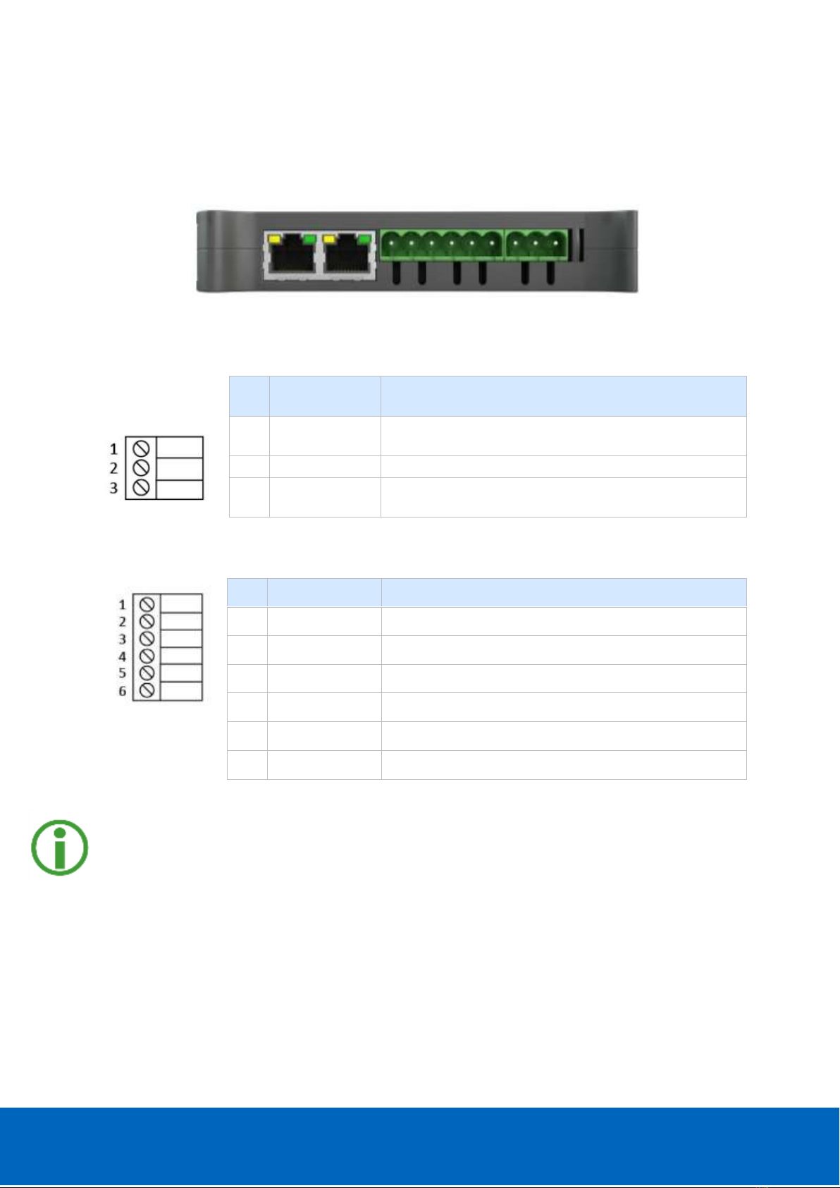
Figure 1: Connectors on top of the body
2.1.1. Power connector
PIN
NAME
DESCRIPTION
1
24 V DC
24V DC ±10%
2
0 VDC
0 V
3
GND
Ground connection
2.1.2. SERIAL connector
Important: The shielding of the SERIAL cable must imperatively have ground connections at
both ends in order to ensure correct electromagnetic disturbances protection. The pin 4 of
the connector may be used. The ideal situation is to use a shield jumper screw, which is
fixed at each end of the serial wire on a ground bus or a cabinet bottom plate.
PIN
NAME
DESCRIPTION
1
Rx
Rx RS232 (VPGate equipment)
2
Tx
Tx RS232 (VPGate equipment)
3
GND
RS232 ground connection
4
Shield
Ground
5
Data -
Signal Data - RS485
6
Data +
Signal Data + RS485
Power
Serial
1
2
3
1
2
3
4
5
6

VPGate EtherNet/IP™ manual | rev. A | September 2017 | ©PROCENTEC 9/109
2.1.3. ETHERNET RJ45 connectors P1 and P2
PIN
NAME
DESCRIPTION
1
Tx+
2
Tx-
3
Rx+
6
Rx-
Important: The shielding of the ETHERNET cable must have ground connections at both
ends in order to ensure correct resistance to electromagnetic disturbances. The body of
the connector may be used. Ideally a shield jumper screw, which is fixed at each end of
the Ethernet wire on a ground bus or a cabinet bottom plate, must be used.
Figure 2: Connectors at the bottom of the case
2.1.4. TOR input
IEC61131-2 compliant, type 1:
PIN
NAME
DESCRIPTION
1
IN +
Insulated TOR input (15-24V)
2
IN -
Insulated TOR input, ground return
2.1.5. TOR output
IEC61131-2 compliant:
PIN
NAME
DESCRIPTION
1
OUT
Relay contact
2
OUT
Relay contact
Breaking capacity: 0.5 A (On resistive load)
Maximum permissible current: 1.2 A
OUT
2
1
IN
2
1
+
-
1
2
1
2
TOR OUT
TOR IN
IN

VPGate EtherNet/IP™ manual | rev. A | September 2017 | ©PROCENTEC 10/109
2.2. Indicators
2.2.1. Front panel indicators
NAME
LIT
DESCRIPTION
BLINKING
DESCRIPTION
ON
Power supply
applied
N/A
ETH
No connection
with an
EtherNet/IP™
scanner
(1Hz)
Communication established with an
application error
SERIAL
No protocol
activated on
the serial link
(1Hz)
Error with the currently enabled serial link
protocol
Until error
disappears
MODBUS
master
One of the scenarios is in
error (timeout, exception
answered, CRC error…)
For 10
seconds on
error
detection
MODBUS slave
Exception answered to a
request from a MODBUS
master. Invalid frame
received (invalid format, bad
CRC)
For 10
seconds on
error
detection
TRANSPARENT
Invalid frame received (frame
too long, bad CRC, no end of
frame detected until
timeout)
RUN
(1Hz)
Firmware is running
Tx
Data sent on the serial link
Rx
Data received on the serial link
2.2.2. Indicators on the 2 ETHERNET connectors
Figure 3: ETHERNET socket with indicators built-in
Link status indicator:
-
Switched off: link down
-
Switched on: link up
Link activity indicator:
-
Switched off: no exchanges
-Blinking: ongoing Tx/Rx

VPGate EtherNet/IP™ manual | rev. A | September 2017 | ©PROCENTEC 11/109
2.3. DIP switches
DIP switches enable:
-Activating a default IP configuration (192.168.10.20),
-Selecting the physical media for the serial link: RS232 or RS485,
-Activating a terminating resistance and polarity of the serial line.
Figure 4: DIP switches
2.3.1. Default configuration of the IP address
A switch allows the setting of a default IP configuration (@IP 192.168.10.20, mask
255.255.255.0) during the start-up of the VPGate Ethernet. The configuration is carried out
in the following manner:
SWITCH
POSITION
DESCRIPTION
1
ON
Default IP configuration
OFF
IP configuration defined by the user
Set the DIP switch 1 to ON and power VPGate OFF and ON to ensure that it takes the default
IP parameters into account.
Important: A user may change the IP address of VPGate via the Web server or via the DCP
protocol, when the switch is set to ON. In this case, the new IP address is used immediately,
despite the switch being activated. Consider setting the switch to OFF, otherwise the default
IP address shall be once again used when the device is restarted.
2.3.2. Choosing the RS232/RS485 mode
There is a switch which allows specifying the operating mode of the serial link from between
RS232 or RS485 (VPGate is pre-set to RS485 out of the box):
SWITCH
POSITION
DESCRIPTION
2
ON
RS232
OFF
RS485

VPGate EtherNet/IP™ manual | rev. A | September 2017 | ©PROCENTEC 12/109
RS232 mode:
Figure 5: Serial network in RS232 mode
This mode can only be used in case of communication between 2 individual devices (point-
to-point connection). The maximum distance in RS232 is 15 meters at 19200 baud.
RS485 mode:
Figure 6: Serial network in RS485 mode
This mode is used more often as it allows connection of several slaves on the bus. It also has
other advantages such as immunity to EMC disturbances and a greater inter-device distance
than in RS232. The maximum distance in RS485 is 1000 meters.
2.3.3. Termination resistance
If the communication mode used is RS485, there must be a termination resistance of 120Ω
at both ends of the segment (refer to the example in paragraph §2.3.2). A termination
resistance is connected using DIP switches 3 and 4 (when delivered, the VPGate is pre-set
without a termination resistor).
SWITCH
POSITION
DESCRIPTION
3 – 4
(activation of the terminating resistor
+ polarisation of the line)
ON
Termination + polarisation
OFF
No termination and no polarisation
To ensure the proper functioning of the termination, switches 3 and 4 must be in the same
position.
VPGate
EtherNet/IP™
Serial Device
VPGate
EtherNet/IP™
Serial
Device
VPGate EtherNet/IP™ manual | rev. A | September 2017 | ©PROCENTEC 13/109
3. EtherNet/IP™
3.1. Operating principle
The VPGate is an EtherNet/IP™ adapter. An EtherNet/IP™ Scanner can access it with implicit
(deterministic) or explicit messaging (acyclic and not deterministic).
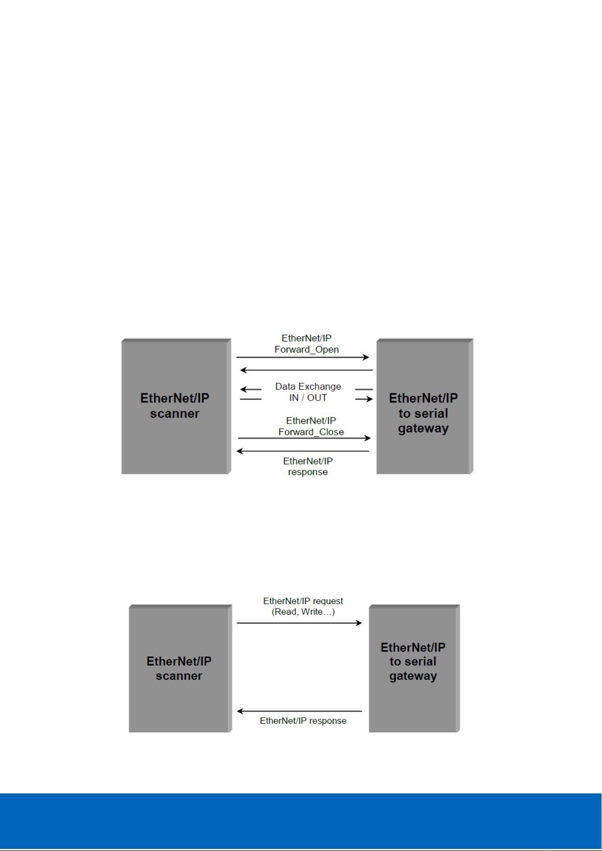
3.1.1. Implicit messaging
Implicit messaging allows data producing/consuming mechanism. The configuration of the
communication (mainly type of communication, data exchanged and cycle time) is sent at
the beginning of the communication with the “Forward Open” service.
As the configuration is sent only once, this communication is more efficient than explicit
messaging.
The data exchange is stopped with “Forward Close” service.
Figure 7: Data exchange in implicit mode
3.1.2. Explicit messaging
Explicit messaging works as client/server. It’s used for non-real-time data access.
It allows access to specific objects (data) by using its services/attributes.
Figure 8: Data exchange in explicit mode
™
™
™
™

VPGate EtherNet/IP™ manual | rev. A | September 2017 | ©PROCENTEC 14/109
3.2. List of available EtherNet/IP™ objects
3.2.1. Identity Object
Identity object (Class code 0x01) has only one instance (instance 1).
3.2.1.1. Instance Attributes
ATTR
ID
ACCESS
RULE
NAME
DATA TYPE
DESCRIPTION OF ATTRIBUTE
VALUE
01h
Get
Vendor ID
UINT
Identification of each vendor
by number
8
02h
Get
Device
Type
UINT
Indication of general type of
product
12 (dec)
0x0C(hex)
03h
Get
Product
Code
UINT
Identification of a particular
product of an individual
vendor
2048
04h
Get
Revision
STRUCT
Revision of the item the
Identity Object represents
Major
Revision
USINT
1
Minor
Revision
USINT
1
05h
Get
Status
WORD
Summary status of device
See Status
description
below
06h
Get
Serial
Number
UDINT
Serial number of device
07h
Get
Product
Name
SHORT_STR
Human readable
identification
110-00014A
Focus on Status attribute:
This attribute represents the current status of the entire device. Its value changes as the
state of the device changes. The Status attribute is a WORD, with the following bit
definitions:
Identity Object Status (attr 5)
BIT (S)
CALLED
DEFINITION
0
Owned
TRUE indicates the device (or an object within the device) has an owner. Within
the Master/Slave paradigm the setting of this bit means that the Predefined
Master/Slave Connection Set has been allocated to a master. Outside the
Master/Slave paradigm the meaning of this bit is TBD.
1
Reserved, shall be 0
2
Configured
TRUE indicates the application of the device has been configured to do
something different than the “out–of–box” default. This shall not include
configuration of the communications.

VPGate EtherNet/IP™ manual | rev. A | September 2017 | ©PROCENTEC 15/109
3
Reserved, shall be 0
4 – 7
Extended Device
Status
Vendor–specific or as defined by Table. The EDS shall indicate if the device
follows a vendor-specific definition for these bits by using the
DeviceStatusAssembly keyword.
8
Minor
Recoverable
Fault
TRUE indicates the device detected a problem with itself, which is thought to be
recoverable. The problem does not cause the device to go into one of the faulted
states. See Behavior section.
9
Minor
Unrecoverable
Fault
TRUE indicates the device detected a problem with itself, which is thought to be
unrecoverable. The problem does not cause the device to go into one of the
faulted states. See Behavior section.
10
Major
Recoverable
Fault
TRUE indicates the device detected a problem with itself, which caused the
device to go into the “Major Recoverable Fault” state. See Behavior section.
11
Major
Unrecoverable
Fault
TRUE indicates the device detected a problem with itself, which caused the
device to go into the “Major Unrecoverable Fault” state. See Behavior section.
12 - 15
Extended Device
Status 2
Reserved - (shall be 0) or vendor-specific. The EDS shall indicate if the device
follows a vendor-specific definition for these bits by using the
DeviceStatusAssembly2 keyword as defined in Section 7-3.6.3, Device
Description Section.
Extended Device Status (Field (bits 4-7) in Status Instance Attribute)
EXTENDED DEVICE STATUS
0
Self-Testing or Unknown
1
Firmware Update in Progress
2
At least one faulted I/O connection
3
No I/O connections established
4
Non-Volatile Configuration bad
5
Major Fault – either bit 10 or bit 11 is true (1)
6
At least one I/O connection in run mode
7
At least one I/O connection established, all in idle mode
8-9
Reserved
10-15
Vendor specific status
3.2.1.2. Instance Services
SERVICE
CODE
SERVICE
NAME
DESCRIPTION OF SERVICE
01h
Get_Attributes
_All
Returns a predefined listing of this objects attributes (See the
Get_Attributes_All Response definition below)
05h
Reset 1
Invokes the Reset service for the device.
0Eh
Get_Attribute
_Single
Returns the contents of the specified attribute.
1: Only the reset type 0 is supported

VPGate EtherNet/IP™ manual | rev. A | September 2017 | ©PROCENTEC 16/109
3.2.2. Assembly Object
3.2.2.1. Class Attributes
ATTR
ID
ACCESS
RULE
NAME
DATA
TYPE
DESCRIPTION OF ATTRIBUTE
VALUE
01h
Get
Revision
UINT
Revision of this object
2
02h
Get
Max
Instance
UINT
Maximum instance number of an
object currently created in this class
level of the device.
199
03h
Get
Number
of
instances
UINT
Number of object instances currently
created at this class level of the
device.
9
3.2.2.2. Instance list
INSTANCE
ID
NAME
DIRECTION
COMMENTS
0x65
(101)
INPUT
T->O
Data from the target to the originator
0x66
(102)
OUTPUT
O->T
Data from the originator to the target
0x67
(103)
STATUS
T->O
Status from the target to the originator
0x68
(104)
Configuration
MODBUS
Master
O->T
MODBUS Master configuration assembly
0x69
(105)
Configuration
MODBUS Slave
O->T
MODBUS Slave configuration assembly
0x6A
(106)
Configuration
TRANSPARENT
O->T
TRANSPARENT configuration assembly
0x6B
(107)
Dummy
Configuration
O->T
Configuration assembly for IO and LO
0xC6
(198)
Heartbeat -
Input only
O->T
Heartbeat
0xC7
(199)
Heartbeat -
Listen only
O->T
Heartbeat

VPGate EtherNet/IP™ manual | rev. A | September 2017 | ©PROCENTEC 17/109
3.2.2.3. Instance Attributes
ATTR
ID
ACCESS
RULE
NAME
DATA TYPE
DESCRIPTION OF ATTRIBUTE
03h
Set
Data
ARRAY of
BYTE
There isn’t any endian conversion on the bytes.

VPGate EtherNet/IP™ manual | rev. A | September 2017 | ©PROCENTEC 18/109
3.2.3. Connection Manager Object
Connection Manager object (Class code 0x06) has only one instance (instance 1)
3.2.3.1. Class Attributes
ATTR
ID
ACCESS
RULE
NAME
DATA TYPE
DESCRIPTION OF ATTRIBUTE
VALUE
01h
Get
Revision
UINT
Revision of this object
1
02h
Get
Max
Instance
UINT
Maximum instance number of
an object currently created in
this class level of the device.
1
03h
Get
Number
of
instances
UINT
Number of object instances
currently created at this class
level of the device.
1
3.2.3.2. Class Services
SERVICE
CODE
SERVICE NAME
SERVICE DESCRIPTION
01hex
Get_Attributes_All
Returns the contents of all attributes of the class.
0Ehex
Get_Attribute_Single
Used to read a Connection Manager Class attribute value.
3.2.3.3. Instance Attributes
ATTR
ID
ACCESS
RULE
ATTRIBUTE
NAME
DATA
TYPE
DESCRIPTION OF ATTRIBUTE
01h
Get
Open
Requests
UINT
Number of Forward Open service requests
received.
02h
Get
Open Format
Rejects
UINT
Number of Forward Open service requests which
were rejected due to bad format.
03h
Get
Open
Resource
Rejects
UINT
Number of Forward Open service requests which
were rejected due to lack of resources.
04h
Get
Open Other
Rejects
UINT
Number of Forward Open service requests which
were rejected for reasons other than bad format or
lack of resources.
05h
Get
Close
Requests
UINT
Number of Forward Close service requests
received.
06h
Get
Close Format
Requests
UINT
Number of Forward Close service requests which
were rejected due to bad format.
07h
Get
Close Other
Requests
UINT
Number of Forward Close service requests which
were rejected for reasons other than bad format.
08h
Get
Connection
Timeouts
UINT
Total number of connection timeouts that have
occurred in connections controlled by this
Connection Manager

VPGate EtherNet/IP™ manual | rev. A | September 2017 | ©PROCENTEC 19/109
3.2.3.4. Instance Services
Common services
SERVICE
CODE
SERVICE NAME
SERVICE DESCRIPTION
01hex
Get_Attributes_All
Returns the contents of all attributes of the class.
0Ehex
Get_Attribute_Single
Used to read a Connection Manager Object instance
attribute.
Object specific services
SERVICE
CODE
SERVICE
NAME
SERVICE DESCRIPTION
4Ehex
Forward_Close
Closes a connection
52hex
Unconnecte
d_Send
Unconnected Send Service. Only originating devices and devices
that route between links need to implement
54hex
Forward_Open
Opens a connection, maximum data size is 511 bytes
Forward Open service parameters:
Network connection parameters:
Fixed/Variable: only fixed size for the amount of data on the connection.
Priority: Not supported
Redundant owner: Not supported.
Connection Path:
Only path to assembly object is supported.

VPGate EtherNet/IP™ manual | rev. A | September 2017 | ©PROCENTEC 20/109
3.2.4. MODBUS Object (Vendor specific)
The MODBUS object provides an interface to MODBUS equipments connected to the serial
port.
Services are provided that directly correspond to the most common MODBUS commands.
MODBUS object is a “vendor specific” object with a class code 0x64. Only one instance is
available in the gateway (instance 0).
Figure 9 - MODBUS device
This object supports the following MODBUS functions as EtherNet/IP™ services:
-1: Read coils
-2: Read Discrete Inputs
-3: Read Holding Registers
-4: Read Input Registers
-15: Write Multiple Coils
-16: Write Multiple Registers
3.2.4.1. Operating principle
By using explicit messaging through the MODBUS Object, the user has access to any data of
any MODBUS slave equipment.
Other manuals for VPGate
3
Table of contents
Other Procentec Gateway manuals


