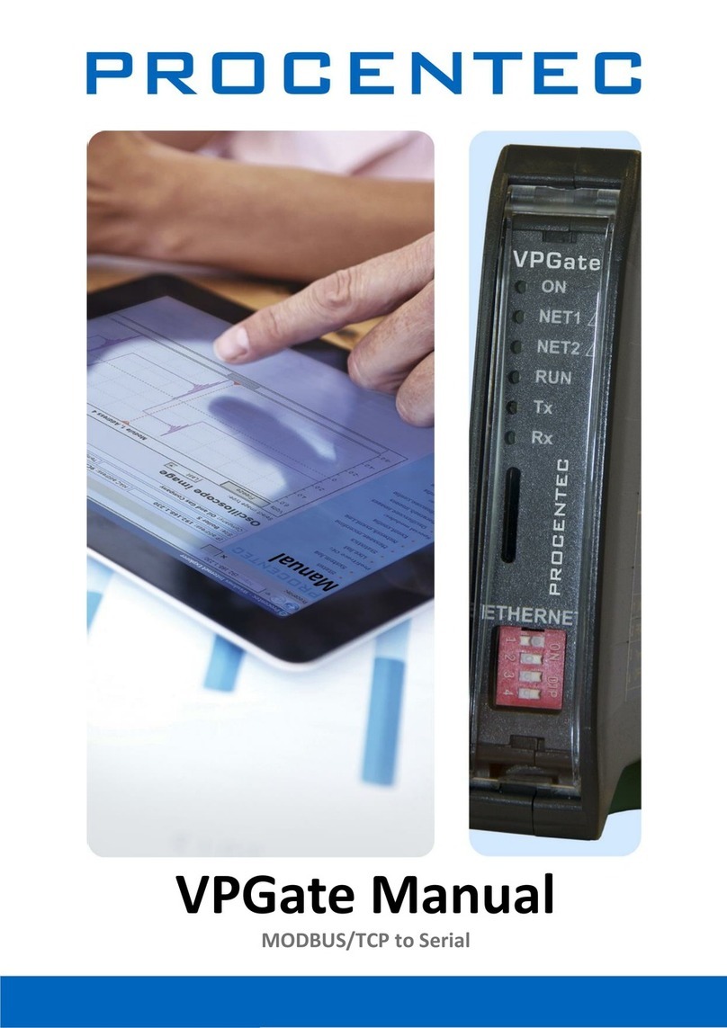
Procentec VPGate User manual

VPGate Manual
PROFIBUS to serial

VPGate PROFIBUS to serial manual | 09 juli 2018 | ©PROCENTEC 2/82
Important information
Purpose of the Manual
This user manual provides information how to work with the VPGate PROFIBUS to serial.
Document Updates
You can obtain constantly updated information on PROCENTEC products on the Internet at
www.procentec.com
You can also contact PROCENTEC Customer Support:
•by phone at +31-(0)174-671800
•by fax at +31-(0)174-671801
•by email at support@procentec.com

VPGate PROFIBUS to serial manual | 09 juli 2018 | ©PROCENTEC 3/82
Content
Important information........................................................................................... 2
1. Technical Specifications................................................................................. 5
1.1 General characteristics ......................................................................................................................5
1.2 Electrical characteristics ....................................................................................................................7
1.3 Mechanical characteristics ................................................................................................................7
2. Hardware Setup............................................................................................. 8
2.1 Connectors pin out ............................................................................................................................8
2.1.1 Power connector ...............................................................................................................................8
2.1.2 SERIAL Connector ..............................................................................................................................8
2.1.3 Digital input .......................................................................................................................................9
2.1.4 Digital output.....................................................................................................................................9
2.2 Front panel indicators......................................................................................................................10
2.3 DIP switches.....................................................................................................................................10
2.3.1 Selecting the RS-232/RS-485 modes ...............................................................................................10
2.3.2 Termination resistance....................................................................................................................11
2.4 Selection of the PROFIBUS address .................................................................................................12
3. Software Setup for PROFIBUS DPV0............................................................ 13
3.1 Configuration tool for PROFIBUS DP Master DPV0 .........................................................................13
3.2 Include VPGate into a project..........................................................................................................13
3.2.1 Import the VPGate GSD file into the third party configuration tool................................................13
3.2.2 Insert VPGate into the network configuration ................................................................................14
3.3 VPGate parameters .........................................................................................................................14
3.3.1 General parameters.........................................................................................................................14
3.3.2 Setup VPGate in TRANSPARENT mode............................................................................................16
3.3.3 Setup VPGate as MODBUS Master ..................................................................................................18
3.3.4 Generic master mode: PASS-FRAME function.................................................................................23
3.3.5 Setup VPGate as MODBUS slave .....................................................................................................24
3.4 Insertion of Input / output modules................................................................................................25
3.4.1 When VPGate is in TRANSPARENT mode ........................................................................................25
3.4.2 When VPGate is in Master MODBUS mode.....................................................................................28
3.4.3 When VPGate is in MODBUS Slave mode........................................................................................29
4. Fail safe mode.............................................................................................. 31
5. DPV1 PROFIBUS acyclic functionalities........................................................32
5.1 Configuration tools of the PROFIBUS DPV1 master.........................................................................32
5.2 Identification Informations..............................................................................................................32
5.3 Acyclic communication in «MODBUS master» mode......................................................................33
5.3.1 Description of the index 0 «COMMAND»........................................................................................34
5.3.2 Description of the index 1 «STATUS» ..............................................................................................34
5.3.3 Description of the index 2 «ADDRESS»............................................................................................35
5.3.4 Description of the index 3 «FUNCTION» .........................................................................................35
5.3.5 Description of the index 4 «OFFSET» ..............................................................................................36
5.3.6 Description of the index 5 «LENGTH» .............................................................................................36

VPGate PROFIBUS to serial manual | 09 juli 2018 | ©PROCENTEC 4/82
5.3.7 Description of the index 6 «DATA» .................................................................................................36
5.4 Example ...........................................................................................................................................36
6. Digital I/O’s .................................................................................................. 38
6.1 Digital output...................................................................................................................................38
6.2 Digital input .....................................................................................................................................38
7. Diagnostic ....................................................................................................40
7.1 PROFIBUS extended diagnostic .......................................................................................................40
7.2 Digital output for diagnostic............................................................................................................42
8. Firmware Update......................................................................................... 43
9. Appendices ..................................................................................................44
Appendix A: List of errors sent by VPGate..................................................................................................44
Appendix B: Format of MODBUS messages................................................................................................49
10. ‘Other PROCENTEC products’......................................................................71
11. Sales offices and distributors.......................................................................73
12. About PROCENTEC....................................................................................... 78
13. Notes ........................................................................................................... 79

VPGate PROFIBUS to serial manual | 09 juli 2018 | ©PROCENTEC 5/82
1. Technical Specifications
1.1 General characteristics
PROFIBUS DPV0 and DPV1
Baud Rate
9.6kbps –12 Mbps (Auto Baud)
Connector
DB9 female
Bus Address
7 DIP switches
PROFIBUS Versions
DP V0, DP V1 (1 connection MS-C1 and 1 connection MS-C2)
Diagnostic
27 bytes of extended diagnostic, 6 status indicators
Input Bytes
0 –244
Output Bytes
0 –244
Max number of
Inputs/Outputs
488
Isolation
1 kV
Others
Sync, Freeze, Fail-Safe
SERIAL LINK
Baud Rate
1200, 2400, 4800, 9600, 19200, 38400, 57600, 115200 baud
Data bits
7 or 8 bits
Interface
RS-232 or RS-485
Distance
Maximum 1200m copper cable without repeater (depending on speed and
cable quality)
Cable
Shielded twisted pair
Connector
Female open style connector 3 contacts

VPGate PROFIBUS to serial manual | 09 juli 2018 | ©PROCENTEC 6/82
Bus termination resistor
120 Ω configurable by switches
TRANSPARANT MODE
End of frame delimiter
EOF character, known length, on timeout
MODBUS MODE
Bus Access
Master or Slave
Protocol
MODBUS RTU or ASCII
Max number of devices
on the network
32
Supported Functions
1, 2, 3, 4, 5, 6, 7, 15, 16; 23
Number of slave
accessible by the master.
20 MODBUS Slaves in PROFIBUS DPV0
247 slaves in PROFIBUS DPV1
Range of slave addresses
1 –247
Number of accessible
MODBUS registers
1 - 122 read registers with PROFIBUS DPV0
1 - 122 write registers with PROFIBUS DPV0
1 –120 read/write registers with PROFIBUS DPV1
Max total number of
accessible MODBUS
registers
244 with PROFIBUS DPV0
Unlimited with PROFIBUS DPV1
Number of messages
1 - 20 different MODBUS messages with PROFIBUS DPV0
Unlimited with PROFIBUS DPV1
Message trigger
Cyclic, On change, Once with PROFIBUS DPV0
On demand with PROFIBUS DPV1

VPGate PROFIBUS to serial manual | 09 juli 2018 | ©PROCENTEC 7/82
INPUT / OUTPUT
1 digital isolated input
0 –24 V
1 relay output
Switch contact (rated current 1.2A, switching current 0.5A)
1.2 Electrical characteristics
POWER SUPPLY
Input Voltage
24V DC +/- 10%
Current consumption
40 mA -1 W at 24V DC
75 mA - 0.9 W at 12V DC
Connector
Open style 3 contacts, female
Polarity protection
Yes
Short circuit protection
Yes
1.3 Mechanical characteristics
MECHANICAL
Housing
Plastic box
IP20 –DIN rail mountable
Dimensions
120 x 100 x 23 mm (L x W x H)
Weight
About 100g
Storage Temperature
-25°C…+70°C
Operating Temperature
0°C…+55°C

VPGate PROFIBUS to serial manual | 09 juli 2018 | ©PROCENTEC 8/82
2. Hardware Setup
2.1 Connectors pin out
2.1.1 Power connector
Pin
Name
Description
1
24 V DC
Power supply 24 V ± 10%
2
0 V DC
Power supply 0 V
3
Earth
Earth
2.1.2 SERIAL Connector
Pin
Name
Description
1
Rx
Rx RS-232 (VPGate < device)
2
Tx
Tx RS-232 (VPgate > device)
3
GND
RS-232 grounding
4
Shield
Earth
5
Data -
Signal Data - RS-485
6
Data +
Signal Data + RS-485
Important: The shield of the SERIAL RS-485 cable must be connected to the earth at each end in
order to protect against EMC. Pin 4 of the connector may be used. In this case the earth pin of the
power connector must be connected.
However, it is better to use a shield clamp, fixed at each end of the serial cable on a grounding rod
or a bottom plate of a cabinet.
Fig. 1 Connector on top of the enclosure
1
2
3

VPGate PROFIBUS to serial manual | 09 juli 2018 | ©PROCENTEC 9/82
Fig. 2 Connectors on bottom of the enclosure
2.1.3 Digital input
IEC61131-2 compliant, type 1:
2.1.4 Digital output
IEC61131-2 compliant:
Interrupting capacity 0.5 A
Maximum accepted current: 1.2 A
Pin
Name
Description
1
IN +
Insulated digital input (15-24 V)
2
IN -
Insulated digital input, ground return
Pin
Name
Description
1
OUT
Relay contact
2
OUT
Relay contact
OUT
2
1
IN
2
1
+
-

VPGate PROFIBUS to serial manual | 09 juli 2018 | ©PROCENTEC 10/82
2.2 Front panel indicators
2.3 DIP switches
DIP switches enable:
•selection of the PROFIBUS address of the device (1 to 126),
•selection of the physical support of the serial link: RS-232 or RS-485,
•activation of a termination and line polarisation in RS-485 mode.
Fig. 3 DIP switches
2.3.1 Selecting the RS-232/RS-485 modes
A switch enables specifying the operating mode of the serial link in RS-232 or RS-485 (when delivered, VPGate
is preset to RS-485):
Name
Lit
Description
Blink
Description
ON
Gateway is powered
PFB
No established communication on
PROFIBUS (BF)
diagnostic related to PROFIBUS
Serial
No reply from a MODBUS slave
diagnostic related to the serial line
RUN
Firmware is running
Tx
Sending on serial line
Rx
Receiving on serial line

VPGate PROFIBUS to serial manual | 09 juli 2018 | ©PROCENTEC 11/82
RS-232 mode:
This mode can only be used in case of communication between 2 individual devices (point-to-point
connection). The maximum distance in RS-232 is 15 m at 19200 baud.
RS-485 mode:
This mode is used more often as it allows connection of several slaves on the bus. It also has other advantages
such as immunity to EMC disturbances and a greater inter-device distance than in RS-232. The maximum
distance in RS-485 is 1200 m.
2.3.2 Termination resistance
If the communication mode used is RS-485, there must be a termination resistance of 120Ω at both ends of the
network. A termination resistance can be added directly in VPGate if it is positioned at the end of a segment. It
is connected using 2 DIP switches (when delivered, VPGate is preset without a termination resistance).
Fig. 6 Termination of the RS-485 bus
Fig. 4 Serial network in RS-232
Fig. 5 Serial network RS-485 mode
Note 1: To ensure proper operation of the termination, the 2 switches must be in the
same position.
Note 2: In RS-232 mode, these 2 DIP switches must be on TERM OFF.

VPGate PROFIBUS to serial manual | 09 juli 2018 | ©PROCENTEC 12/82
2.4 Selection of the PROFIBUS address
Use the switches 1,2,4,8,16,32,64 to select the PROFIBUS address of the VPGate. (VPGate default factory setting
is address 3). The label next to each switch corresponds to its weight.
PROFIBUS address must be set to a value between 0 and 126.
Ex: To set address 3, set the switches 1 and 2 to ON.
Fig. 7 PROFIBUS address set to 3

VPGate PROFIBUS to serial manual | 09 juli 2018 | ©PROCENTEC 13/82
3. Software Setup for PROFIBUS DPV0
3.1 Configuration tool for PROFIBUS DP Master DPV0
The setup of VPGate PROFIBUS to serial is done using the configuration tool of the PROFIBUS network. The
configuration is automatically sent to the PROFIBUS slaves (VPGate PROFIBUS) during the network initialisation
phase.
The detailed configurations hereafter was created as examples using the PROFIBUS configuration tools from
third party vendors, "Console" of Woodhead and "HW Config" of SIEMENS. However the principle is the same
with other PROFIBUS master configuration tools of the market place.
3.2 Include VPGate into a project
Before to continue, it is mandatory to create a project into the third party configuration tool. The project must
include a PROFIBUS network and a master port.
3.2.1 Import the VPGate GSD file into the third party configuration tool.
This GSD file allows you to use the VPGate as a PROFIBUS slave device. It is named PROC6980.GSD and it is
located on our website under PROCENTEC https://procentec.com/service-support/gsd-files. It is necessary to
import this GSD file into the third party configuration PROFIBUS to have the VPGate device appearing in the list
of slave devices to be included on the network.
HW config. TIA portal
Console, Woodhead

VPGate PROFIBUS to serial manual | 09 juli 2018 | ©PROCENTEC 14/82
Console, Woodhead
Console, Woodhead
3.2.2 Insert VPGate into the network configuration
The different stages are as follows:
•From the list of PROFIBUS devices, insert VPGate on the network.
•Setup the appropriate PROFIBUS address of the VPGate (this value must match with the one configured on
the VPGate hardware (DIP switches)
3.3 VPGate parameters
3.3.1 General parameters
Once VPGate is inserted into the PROFIBUS network configuration, it is necessary to configure the serial line.
HW config. TIA portal
Note: The communication baudrate of VPGate is automatically defined according to the
configuration of the PROFIBUS DP master.
HW config. TIA portal

VPGate PROFIBUS to serial manual | 09 juli 2018 | ©PROCENTEC 15/82
Name
Description
Possible values
Baudrate
Baudrate of the serial link (in bits/s)
1200
2400
4800
9600
19200
38400
57800
115200
Data bits (*)
Number of data bits
7
8
Stop bits and parity
bit (**)
Number of stop bits and parity bit specification
No parity / 1 stop
No parity / 2 stops
Even parity / 1 stop
Odd parity / 1 stop
Timeout
Timeout on serial link in reception
10 ms
100 ms
500 ms
1000 ms

VPGate PROFIBUS to serial manual | 09 juli 2018 | ©PROCENTEC 16/82
Console, Woodhead
Name
Description
Possible values
Protocol selection
Mode selection
MODBUS RTU
MODBUS ASCII
transparant
Extended diagnosis
Enable or disable PROFIBUS extended diagnosis
Enabled
Disabled
Interframe silence
Specifies a time that must be respected between
received and transmitted frames in ms.
20 –65535 ms
(*) In MODBUS RTU, data are coded on 8 bits. In MODBUS ASCII, data are coded on 7 bits. In those modes,
parameter "data bits" is ignored.
(**) In MODBUS ASCII, if there is not parity bit ("No parity"), others MODBUS equipments on the network must
be configured with 2 stop bits.
3.3.2 Setup VPGate in TRANSPARENT mode
In this mode, data exchange is full duplex on the serial link, without any master / slave relation. Frames detected
over the serial link are immediately transferred to the PROFIBUS inputs, starting at the offset 0. Also, if a serial
frame format is detected in the PROFIBUS outputs, it is immediately transferred to the serial link. In order to do
so, it is necessary to define how frames are delimited.
To setup VPGate in transparent mode:
•Set the parameter "Protocol selection" on "TRANSPARENT":
HW config. TIA portal

VPGate PROFIBUS to serial manual | 09 juli 2018 | ©PROCENTEC 17/82
Console, Woodhead
•Then setup parameters dedicated to transparent mode:
Name
Description
Possible values
EOF delimiter (1)
Defines how an end of frame will be detected
NULL (0x00)
SPACE (0x20)
LF (0x0A)
CR (0x0D)
CR LF
LF CR
User defined
Length in 1st byte
On timeout (2)
Fill-in unused bytes
(3)
Defines if unused bytes in PROFIBUS inputs frame must
be modified in end of frame character
Enabled
Disabled
Add frames
counter (4)
Defines if a frame counter is added at the beginning of
PROFIBUS inputs and outputs frames
Enabled
Disabled
Add and control
CRC 16
Defines if a CRC16 must be checked in the data received
from the serial equipment, and must be added to the
data sent to the serial equipment.
Enabled
Disabled
HW config. TIA portal

VPGate PROFIBUS to serial manual | 09 juli 2018 | ©PROCENTEC 18/82
(1): If this parameter is set on User defined, the end of frame character taken into account is the one specified
by parameter "User defined EOF". If it is set as on timeout, the reception timeout taken is the one defined in
the serial link configuration.
(2): When "EOF delimiter" is set to on timeout, only detection of frames received from serial line is on timeout.
On PROFIBUS side, 1st byte must be used to specify the length of received/sent frame (cf. §3.4.1).
(3): When "EOF delimiter" is set on length in 1st byte or on timeout, the filled value is 0x00.
(4): This counter is used as a trigger:
•If this parameter is enabled, 1st byte of PROFIBUS outputs must be a counter incremented each time data
are available and must be sent. Relevant data begin at 2nd byte. Otherwise, the frame is copied from the
1st byte as soon as a change on PROFIBUS outputs is detected.
•If this parameter is enabled, 1st byte of PROFIBUS inputs is incremented each time a new frame was
received on serial link. Useful data are copied following this counter. Otherwise, received frame is copied
from the 1st byte.
The inter frame silence parameter leads to the following behaviour:
If there is no recently detected frame, VPGate sends frames through the serial line without waiting for an inter
frame time. But, when there is a detected frame through the RX line, VPGate will wait for the inter frame time
before sending the following frame through TX.
3.3.3 Setup VPGate as MODBUS Master
To use VPGATE as MODBUS master, proceed as follows:
•Adjust first of all parameter "Protocol selection" on "MODBUS RTU" or "MODBUS ASCII" depending on the
protocol used.
Note: Each principle in TRANSPARENT mode is detailed in §3.4.1.

VPGate PROFIBUS to serial manual | 09 juli 2018 | ©PROCENTEC 19/82
•Select then the parameter "VPGate Master/Slave" on "Master".
•Then setup general parameters dedicated to MODBUS master mode: "CRC/LRC" and "Retries"
Name
Description
Possible values
CRC / LRC
Defines if CRC (MODBUS RTU) or LRC (MODBUS ASCII)
must be controlled
Enabled
Disabled
Retries
Number of iterations before signalling a timeout
0
1
2
3
Set the parameter “inter frame silence” to specify the minimum time VPGate can take to send a new MODBUS
request to a slave after receiving the last reply (see the figure below).
HW Config, TIA portal
Console, Woodhead
HW Config, TIA portal
Console, Woodhead

VPGate PROFIBUS to serial manual | 09 juli 2018 | ©PROCENTEC 20/82
•Then setup the different scenarios in order to define the different MODBUS commands to be sent as well as
how VPGate is going to send them:
HW Config, TIA portal
Console, Woodhead
Other manuals for VPGate
3
Table of contents
Other Procentec Gateway manuals
Popular Gateway manuals by other brands
Mennekes
Mennekes eMobility-Gateway Professional+ OPERATING AND INSTALLATION Manual

Elecsys
Elecsys RediGate 400 Series Hardware manual
CommScope
CommScope Touchstone TG6452 user guide
RTA
RTA 460TCP-N2E Product user guide
Micro control systems
Micro control systems MCS-BMS-GATEWAY Startup guide
Anyfi Networks
Anyfi Networks Carrier Wi-Fi System reference guide
