Procentec VPGate User manual

VPGate Manual
MODBUS/TCP to Serial

VPGate manual - MODBUS/TCP to serial V1.0.0 | 30 juni 2017 | ©PROCENTEC 2/135
Content
1. Characteristics ............................................................................................... 6
1.1 General characteristics ......................................................................................................................6
1.2 Electrical characteristics ....................................................................................................................8
1.3 Mechanical/Environmental characteristics .......................................................................................8
2. Hardware installation .................................................................................... 9
2.1 Connector ..........................................................................................................................................9
2.1.1 Power connector ...............................................................................................................................9
2.1.2 SERIAL Connector ..............................................................................................................................9
2.1.3 Digital input .....................................................................................................................................10
2.1.4 Digital output...................................................................................................................................10
2.2 Front panel indicators......................................................................................................................10
2.2.1 Indicator light of the 2 ports switch ................................................................................................11
2.3 DIP switches.....................................................................................................................................11
2.3.1 Default configuration of the IP address...........................................................................................11
2.3.2 Choosing the RS-232/RS-485 mode.................................................................................................12
2.3.3 Terminating resistance ....................................................................................................................12
3. Working principle ........................................................................................ 14
3.1 Appliance of the product.................................................................................................................14
3.2 Default configuration.......................................................................................................................14
3.3 Configuration in “Advanced Gateway” mode .................................................................................15
3.4 MODBUS/TCP server .......................................................................................................................17
3.5 MODBUS/TCP client ........................................................................................................................18
3.6 MODBUS serial link master (1) ........................................................................................................19
3.6.1 MODBUS master with the “Direct messaging” function .................................................................19
3.6.2 Fault management in direct messaging...........................................................................................20
3.6.3 MODBUS master scenarios..............................................................................................................21
3.7 MODBUS serial link slave (2) ...........................................................................................................22
3.8 Transparent Mode (3)......................................................................................................................23
3.8.1 Case where the end of the frame is detected thanks to a special character ..................................23
3.8.2 Case where the Length of frame is known ......................................................................................24
3.8.3 Case where the end of the frame is detected following timeout....................................................25
3.8.4 Functioning of the frame trigger .....................................................................................................25
3.9 Principle of configuration of the product ........................................................................................26
4. Software configuration................................................................................ 27
4.1Procedure to access the VPGate Web server ..................................................................................27
4.2 Procedure for configuring the serial link .........................................................................................28
4.3 Procedure for configuring the MODBUS/TCP server.......................................................................29
4.4 Procedure for configuring the MODBUS serial link master .............................................................30
4.5 Procedure for configuring the MODBUS serial link slave ................................................................31
4.6 Procedure for configuring transparent mode .................................................................................32
5. Implementation of the Default Configuration............................................. 33
5.1 Configuration of the IP address using the DIP switch......................................................................33
5.2 Configuration of the IP address using the DCP protocol .................................................................37

VPGate manual - MODBUS/TCP to serial V1.0.0 | 30 juni 2017 | ©PROCENTEC 3/135
5.3 Configuration of the serial link ........................................................................................................39
5.4 Operating test of the default gateway ............................................................................................41
6. Implementation of the advanced configuration ......................................... 42
6.1 MODBUS/TCP server .......................................................................................................................42
6.1.1 General information regarding the MODBUS/TCP server ...............................................................43
6.1.2 Configuration of the MODBUS/TCP server ......................................................................................44
6.2 MODBUS/TCP client ........................................................................................................................45
6.2.1 Activation of the MODBUS/TCP client.............................................................................................45
6.2.2 Creation of scenarios for the MODBUS/TCP client..........................................................................45
6.2.3 Status of scenarios for the MODBUS/TCP client .............................................................................49
6.2.4 Deactivation of a MODBUS/TCP client scenario..............................................................................50
6.2.5 Modification or deletion of a MODBUS/TCP client scenario...........................................................50
6.2.6 Backing-up the list of MODBUS/TCP scenarios ...............................................................................51
6.3 MODBUS MASTER ...........................................................................................................................52
6.3.1 Activation of the MODBUS serial link master..................................................................................52
6.3.2 Configuration of the MODBUS serial link master ............................................................................52
6.3.3 Creation of the MODBUS serial link master scenarios ....................................................................54
6.3.4 Status of the MODBUS serial link master scenarios ........................................................................58
6.3.5 Deactivation of a MODBUS serial link master scenario...................................................................59
6.3.6 Modification or deletion of a MODBUS serial link master scenario ................................................59
6.3.7 Backing-up the list of MODBUS master...........................................................................................60
6.4 MODBUS SLAVE ...............................................................................................................................61
6.4.1 Activation of the MODBUS serial link slave .....................................................................................61
6.4.2 Configuration of the MODBUS serial link slave ...............................................................................61
6.5 TRANSPARENT MODE ......................................................................................................................63
6.5.1 Activation of the MODBUS serial link slave .....................................................................................63
6.5.2 Configuration of transparent mode on the serial link .....................................................................64
7. DIGITAL INPUT/OUTPUT .............................................................................. 67
7.1 Configuration of the digital input/output........................................................................................67
8. DIAGNOSTICS............................................................................................... 68
8.1 Explanation of the LEDs ...................................................................................................................68
8.2 Diagnostics with status of MODBUS master scenarios....................................................................69
8.3 Diagnostics with status of the MODBUS/TCP client scenarios ........................................................70
8.4 Statistics of the MODBUS master ....................................................................................................72
8.5 Web page of the MODBUS slave statistics ......................................................................................73
9. Web server .................................................................................................. 74
9.1 Presentation of the Web server ......................................................................................................74
9.2 Management of access to the Web server......................................................................................75
9.3 “System information” menu............................................................................................................76
9.4 “Network settings” menu ................................................................................................................76
9.5 “Gateway mode” menu ...................................................................................................................77
9.6 “Modbus/TCP settings” menu.........................................................................................................77
9.7 “Serial settings” menu .....................................................................................................................77
9.8 “IO settings” menu ..........................................................................................................................77
9.9 “SNMP information” menu .............................................................................................................78
9.10 “ETHERNET statistics” menu............................................................................................................78

VPGate manual - MODBUS/TCP to serial V1.0.0 | 30 juni 2017 | ©PROCENTEC 4/135
9.11 “MODBUS Statistics” menu .............................................................................................................80
9.12 “File system” menu .........................................................................................................................81
9.13 “Firmware upload” menu ................................................................................................................82
9.14 “Reboot” Menu ...............................................................................................................................83
9.15 “Passwords” Menu ..........................................................................................................................83
9.16 “Logout” Menu ................................................................................................................................84
9.17 “Custom” menu / Customised WEB pages ......................................................................................84
9.18 Access to data via personalised Web pages ....................................................................................84
9.19 Example of customised WEB pages.................................................................................................85
10. FTP server .................................................................................................... 87
11. SNMP agent ................................................................................................. 88
12. APPENDICES................................................................................................. 90
12.1 APPENDIX A: Format of the MODBUS frames .................................................................................90
12.2 APPENDIX C: API CGI Javascript.................................................................................................... 104
12.3 APPENDIX E: MIB2, important fields ............................................................................................ 115
13. Other PROCENTEC products...................................................................... 124
14. Sales offices and distributors..................................................................... 126
15. About PROCENTEC..................................................................................... 131
16. Notes ......................................................................................................... 132

VPGate manual - MODBUS/TCP to serial V1.0.0 | 30 juni 2017 | ©PROCENTEC 5/135
Document reference
Reference
Document
Version
Date
(1)
MODBUS application protocol specification
V1.1b3
26-04-2012
(2)
MODBUS over serial line specification and implementation guide
V1.02
20-12-2006
(3)
MODBUS messaging on TCP/IP implementation guide
V1.0b
31-10-2006

VPGate manual - MODBUS/TCP to serial V1.0.0 | 30 juni 2017 | ©PROCENTEC 6/135
1. Characteristics
1.1 General characteristics
Ethernet connection
Bandwidth
10/100 Mbps, auto negotiation, auto polarity, auto MDI/MDIX
Lights
Connection active (green) and activity (orange)
Distances
Maximum 100m
Cable
Shielded industrial Ethernet cable (5th category at least)
Connectors
2 RJ-45 connectors with transformer insulation and shield connection
Supported protocols
MODBUS/TCP, SNMP V1, HTTP, FTP, DCP
Switch
Integrated 2 ports switch
MODBUS / TCP
Operating modes
Client, server or gateway
Gateway mode
Direct access by ‘tunnelling’ in the series equipment data
Max number of
simultaneous TCP
connections
5
Port
502

VPGate manual - MODBUS/TCP to serial V1.0.0 | 30 juni 2017 | ©PROCENTEC 7/135
Transparant mode
End of frame
delimiter
End of frame character / known length / on timeout
MODBUS mode
Bus access
Master or slave
Protocol
MODBUS RTU or ASCII
Accepted functions
1, 2, 3, 4, 5, 6, 15, 16, 23
Number of
addressable slaves in
master mode
100 MODBUS slaves
Range of addresses
1 - 247
Number of MODBUS
registers accessible
for a request
1 - 125 registers in read mode
1 - 2000 bits in read mode
1 - 123 registers in write mode
1 - 1968 bits in write mode
Periodicity of sending
frames
Cyclical or following change for writing outputs
Local I/O
TOR input
1 isolated digital input
TOR output
1 isolated digital output
File system
Space available
8 MB
Access
FTP, HTTP

VPGate manual - MODBUS/TCP to serial V1.0.0 | 30 juni 2017 | ©PROCENTEC 8/135
1.2 Electrical characteristics
1.3 Mechanical/Environmental characteristics
Power supply
Supply voltage
12 - 30V DC
Consumption
1.7 W
Connector
Female 3 contact disconnectable terminal (VCC, 0V, GND)
Reverse polarity
protection
Yes
Short-circuit
protection
Yes
Mechanical/environmental characteristics
Type of body
Plastic with hatch on the front side
IP20 - DIN fixation rail
Dimensions
120 x 100 x 23 mm (L x W x H)
Weight
130 g
Storage temperature
-25°C .. +70 °C
Operating
temperature
0°C .. +55 °C
Relative ambient
humidity
Max. 80%

VPGate manual - MODBUS/TCP to serial V1.0.0 | 30 juni 2017 | ©PROCENTEC 9/135
2. Hardware installation
2.1 Connector
Figure 1: Connectors on top of the body
2.1.1 Power connector
Pin
Name
Description
1
24 VDC
Power supply 12 - 30 V
2
0 VDC
0 V
3
GND
Ground connection
2.1.2 SERIAL Connector
Pin
Name
Description
1
Rx
Rx RS-232 (VPGate < equipment)
2
Tx
Tx RS-232 (VPgate > equipment)
3
GND
RS-232 ground connection
4
Shield
Ground
5
Data -
Signal Data - RS-485
6
Data +
Signal Data + RS-485
Important: The shielding of the SERIAL cable must imperatively have ground connections at both
ends in order to ensure correct resistance to electromagnetic disturbances. The pin 4 of the
connector may be used. The ideal situation is to use a shield jumper screw, which is fixed at each
end of the serial wire on a ground bus or a cabinet bottom plate.
1
2
3

VPGate manual - MODBUS/TCP to serial V1.0.0 | 30 juni 2017 | ©PROCENTEC 10/135
2.1.3 Digital input
Figure 2: Connectors on the bottom of the body
IEC61131-2 compliant, type 1:
2.1.4 Digital output
IEC61131-2 compliant:
Interrupting capacity 0.5 A
Maximum accepted current: 1.2 A
2.2 Front panel indicators
Pin
Name
Description
1
IN +
Insulated digital input (15-24 V)
2
IN -
Insulated digital input, ground return
Pin
Name
Description
1
OUT
Relay contact
2
OUT
Relay contact
1
ON
2
Net1
3
Net2
4
RUN
5
Tx (serial link)
6
Rx (serial link)
OUT
2
1
IN
2
1
+
-

VPGate manual - MODBUS/TCP to serial V1.0.0 | 30 juni 2017 | ©PROCENTEC 11/135
1ON: is lit on when the gateway has been powered on.
2Net1 : is lit and steady if the MODBUS/TCP server has not started owing to an error in configuration. Net
1 blinks if the MODBUS/TCP client detects a timeout on a server.
3Net2 : is lit and steady if selected protocol for the serial link has not started owing to an error in
configuration. Net 2 blinks in case of a communication error in the serial link (Timeout of a MODBUS slave,
for example).
4RUN: blinking at 1Hz, indicates that the program is functioning correctly. Blinking at 4Hz indicates that the
"DCP blink" command has been initiated (allows physically locating the equipment).
5Tx: indicates that a frame is being sent on the serial link.
6Rx: indicates that a frame is being received on the serial link.
2.2.1 Indicator light of the 2 ports switch
2.3 DIP switches
DIP switches enable:
•activating a default IP configuration (192.168.10.20)
•selecting the physical support of the serial link: RS-232 or RS-485
•activating a termination resistance and line polarisation
Figure 3: DIP switches
2.3.1 Default configuration of the IP address
A switch allows resetting a default configuration (@IP 192.168.10.20, mask 255.255.255.0) during the start-up
of VPGate Ethernet. The configuration is carried out in the following manner:
Set the DIP switch 1 to ON and power VPGate one and off to ensure that it takes the default IP parameters into
account.
Switch
Name
Description
1
ON
Default IP configuration
OFF
User-defined IP configuration
Link status indicator:
•
Not switched on: no link
•Switched on: Ethernet link OK
Link activity indicator:
•Switched off: no exchanges
•
Switched on: exchanges in progress
VPGate manual - MODBUS/TCP to serial V1.0.0 | 30 juni 2017 | ©PROCENTEC 12/135
Important: A user may modify the IP address of VPGate via the Web server or via the DCP protocol,
when the switch is set to ON. In this case, the new IP address is used immediately, despite the
switch being activated. Consider setting the switch to OFF, otherwise the default IP address shall be
once again used when the device is restarted.
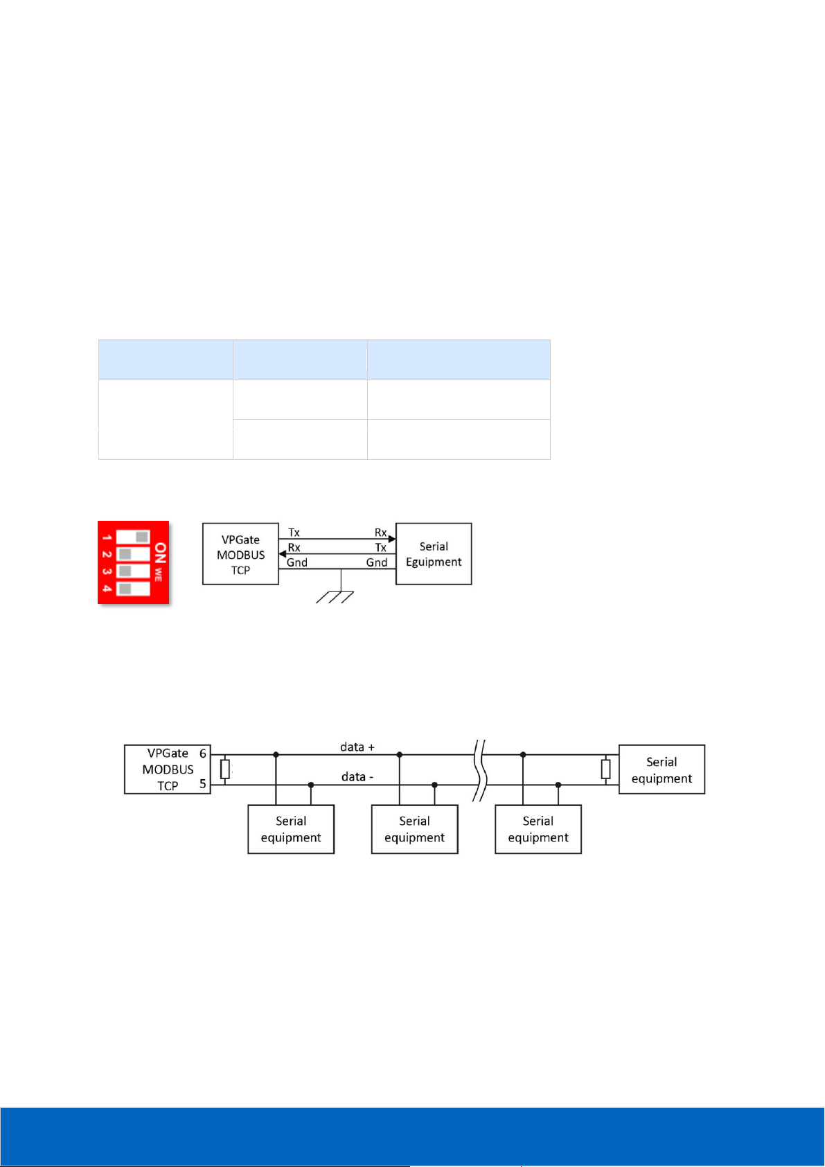
2.3.2 Choosing the RS-232/RS-485 mode
There is a switch which allows specifying the operating mode of the serial link from between RS-232 or RS-485
(VPGate is pre-set to RS-485 out of the box):
RS-232 mode:
Figure 4 : Serial network in RS-232 mode
This mode can be used in case of communication between 2 pieces of equipment only (point to point
connection). The maximum distance in RS-232 is 15 m at 19200 baud.
RS-485 mode:
Figure 5: Serial network in RS-485 mode
This mode is used more often because it allows connecting several slaves on the bus. It also has other
advantages like immunity to EMC disturbances and its maximum inter-equipment distance is higher than in RS-
232 mode. The maximum distance in RS-485 is 1200 m.
2.3.3 Terminating resistance
Switch
Name
Description
2
ON
RS-232
OFF
RS-485
150 Ω
150 Ω

VPGate manual - MODBUS/TCP to serial V1.0.0 | 30 juni 2017 | ©PROCENTEC 13/135
If the communication mode used is RS-485, there must be a terminating resistance of 150Ω at both ends of the
network (refer to the example above). The connection of a terminating resistance is established using DIP
switches 3 and 4 (VPGate is pre-adjusted without terminating resistance):
To ensure the proper functioning of the termination, switches 3 and 4 must mandatorily be in the same
position
Internal resistance and polarisation diagram of the bus RS-485:
Figure 6 : Terminating resistance and polarisation of the bus RS-485
Switch
Position
Description
3 –4
(activation of the terminating
resistance + polarisation of the line)
ON
Termination & polarisation
OFF
No termination and no
polarisation

VPGate manual - MODBUS/TCP to serial V1.0.0 | 30 juni 2017 | ©PROCENTEC 14/135
3. Working principle
3.1 Appliance of the product
VPGate MODBUS/TCP to serial is a communication gateway which allows interfacing a MODBUS/TCP network
with:
1MODBUS serial link slaves (1)
2MODBUS serial link master (2)
3equipment using a proprietary serial link protocol (3)
Figure 7: Presentation of the VPGate MODBUS/TCP to serial operating modes
3.2 Default configuration
VPGate MODBUS/TCP to serial is delivered with a default configuration that allows interfacing MODBUS/TCP
clients with MODBUS serial link slaves:

VPGate manual - MODBUS/TCP to serial V1.0.0 | 30 juni 2017 | ©PROCENTEC 15/135
Figure 8: Operating mode of the default configuration
VPGate is configured in the following mode:
•Ethernet of MODBUS/TCP server
•MODBUS serial link master
The “Direct messaging” mode is activated by default and ensures the transformation of the MODBUS/TCP
messages into MODBUS serial frames. Refer to section 3.6.1 MODBUS master with the “Direct messaging”
function for more information about this mode.
In this mode, VPGate MODBUS/TCP to serial is operational after:
•The IP address parameters are configured
•The serial link to be used (RS-232 or RS-485) and its associated parameters are chosen
Refer to section 5 Implementation of the Default Configuration on page 33 to use VPGate MODBUS/TCP in its
default configuration.
For more information about the MODBUS/TCP protocol, refer to the document MODBUS messaging on TCP/IP
implementation guide.
3.3 Configuration in “Advanced Gateway” mode
The advanced configuration mode allows using the internal memory of VPGate to exchange information
between the MODBUS/TCP and serial link protocols.
VPGate MODBUS/TCP has a shared memory zone called “exchange table” used to store data exchanged
between MODBUS/TCP and the serial link protocols.
When VPGate functions as a MODBUS/TCP server, the exchange table can be accessed by MODBUS/TCP clients
who send read/write requests to VPGate.
When VPGate functions as a MODBUS/TCP, it arranges the data read in the servers in its exchange table, and
from there reads the data to be written on the servers.
The exchange table consists of 16 bit registers in the BIG-ENDIAN format.
Each register is identified by an address (offset) which is coded using 16 bits. The accessible memory range
starts at the address “0x0000” and extends to the address “0xFFFF”. It is defined as indicated below:

VPGate manual - MODBUS/TCP to serial V1.0.0 | 30 juni 2017 | ©PROCENTEC 16/135
Address
Exchange Table (shared memory)
Dec.
Hex.
0
2047
0x0000
0x07FF
Inputs
Data received from the serial link:
•In MODBUS master mode: data read in the slaves
•In MODBUS Slave mode: data written by a master
•In Transparent mode: frame received on the serial link
2048
4095
0x0800
0x0FFF
Outputs
Data sent to the serial link:
•In MODBUS master mode: data written in the slaves
•In MODBUS Slave mode: data read by a master
•In Transparent mode: frame sent on the serial link
4096
32767
0x1000
0x7FFF
Free zone
Accessible only for the following MODBUS functions:
•3 - Read Holding Registers
•4 - Read Input Registers
•6 - Write Single Register
•16 - Write Multiple Registers
•23 - Read/Write Multiple Registers
32768
65535
0x8000
0xFFFF
Configuration zone
•Identification of the product
•Parameters of the serial link:
•Listings of the active protocols
•Configuration of each protocol
Figure 3: Exchange Table (shared memory) of VPGate MODBUS/TCP to serial
The access rules for the exchange table are as follows:
If the “Direct messaging” mode has not been activated, the exchange table can be accessed by a MODBUS/TCP
client irrespective of the slave address specified in the MODBUS/TCP message.
If the “Direct messaging” mode has been activated, the exchange table can be accessed if the slave provided in
the MODBUS/TCP is between 247 and 254.
Important: The configuration field contains the current VPGate parameters. Accessing this field in
write mode can have a direct impact on the proper functioning of the product.

VPGate manual - MODBUS/TCP to serial V1.0.0 | 30 juni 2017 | ©PROCENTEC 17/135
3.4 MODBUS/TCP server
VPGate can be configured to function as a MODBUS/TCP server. It provides the exchange table to the
MODBUS/TCP clients present on the network:
Figure 9: VPGate in MODBUS/TCP server mode
In this mode, it is necessary to configure the IP address of the MODBUS/TCP server used by VPGate, and the list
of MODBUS functions that it supports.
The list of functions supported by VPGate in MODBUS/TCP server mode is as follows:
Code
Function
Maximum length
1
Read coils
2000 bits
2
Read discrete inputs
2000 bits
3
Read holding registers
125 registers
4
Read input registers
125 registers
5
Write single coil
1 bit
6
Write single register
1 register
7
Read exception status
1 byte
15
Write multiple coils
1968 bits
16
Write multiple registers
123 registers
23
Read/Write Multiple registers
125 registers in read mode, 118 in write mode

VPGate manual - MODBUS/TCP to serial V1.0.0 | 30 juni 2017 | ©PROCENTEC 18/135
All requests that include a function code which is not supported shall receive in response the exception "0x01
Illegal Function".
3.5 MODBUS/TCP client
VPGate can be configured to function as a MODBUS/TCP client.
Figure 10: VPGate in MODBUS/TCP client mode
The user can define MODBUS “scenarios" in order to define the behaviour of the MODBUS/TCP client. Each
MODBUS scenario is defined by:
•The IP address of the MODBUS/TCP server to be accessed
•MODBUS function used
•Address of the bit/register to be accessed in the slave
•Quantity of bits/registers to be accessed in the slave
•Address in VPGate, where the read/written data are stored in the slave
•Release mode of the scenario:
•Cyclical sending: definition of a sending period
•Sending after change: the request is sent only if a change is detected in the exchange table (only for
MODBUS write requests)
The cyclical scenarios are executed one after the other. If a scenario has been configured to be executed after a
change and if the data associated with it do indeed change, it is executed immediately after the completion of
the ongoing cyclical scenario.
If several scenarios have been configured to be executed after a change and if the associated data does indeed
change, these scenarios are included in the transmission pending queue.
If no cyclical scenario needs to be sent, the change scenarios are executed one after the other.

VPGate manual - MODBUS/TCP to serial V1.0.0 | 30 juni 2017 | ©PROCENTEC 19/135
If several cyclical scenarios are already pending transmission, VPGate inserts a change scenario between each
ready cyclical scenario, and thus optimises the exchanges by minimising the delay induced during cyclical
scenarios.
3.6 MODBUS serial link master (1)
VPGate can be configured to function as a MODBUS serial link master.
There are two operating modes which allow sending requests to MODBUS slaves:
•The “Direct Messaging” mode (MODBUS/TCP server activated mode)
•Using the scenarios (configuration of the cyclical/acyclical requests)
3.6.1 MODBUS master with the “Direct messaging” function
To access a MODBUS serial slave through VPGate, a MODBUS/TCP client must specify the address of the
MODBUS serial slave which it wishes to connect to:
Figure 11: VPGate serial link master with “Direct messaging”
It enters this information in the field “Unit ID” of the “MBAP” header of the MODBUS/TCP message (refer to
Figure : Figure 12: Conversion of a MODBUS/TCP message into a MODBUS serial frame).
By sending the MODBUS/TCP message to the IP address of the VPGate MODBUS/TCP server, VPGate shall then
convert the TCP message into a serial link frame as indicated below:
Figure 12: Conversion of a MODBUS/TCP message into a MODBUS serial frame
Slave
address
Function
code
Data
CRC
Unit ID
Function
code
Data
Length
Request
Protocol ID
ID
Transaction
MODBUS serial frame
MODBUS request (PDU)
MBAP: MODBUS/TCP header
MODBUS/TCP message (ADU)

VPGate manual - MODBUS/TCP to serial V1.0.0 | 30 juni 2017 | ©PROCENTEC 20/135
For more information about the MODBUS: MODBUS application protocol specification [1].
The field “Unit ID” is used as a slave address in order to create the MODBUS serial frame.
VPGate can thus create and send a serial frame from the TCP message, and return the response from the slave
to the requesting client, via its IP address.
VPGate is distributed through a default configuration when this operating mode is used, refer to section 3.2
Default configuration .
There may be a latency in the time taken by the MODBUS serial slave to process the request. A MODBUS/TCP
client must thus always wait for the MODBUS serial link request to be executed in order to receive a response
from the VPGate MODBUS/TCP server.
It is possible that a MODBUS/TCP request may be considered as unanswered (timeout) by a client, even though
it is only because of the lead-through time that the time required for transmitting the message is extended.
In this case, the value of the “timeout” parameter of the requests on the client must be increased.
This mode is functional, but not at the same level of performance as the “Advanced Gateway” mode which is
presented in section 3.3 Configuration in “Advanced Gateway” mode
3.6.2 Fault management in direct messaging
If a corrupted frame is received by the MODBUS slave, the request is ignored and no response is sent to the
MODBUS master.
If a corrupted response is received by the master, the frame is ignored. This is considered as a timeout.
If the frame received from the slave is correct, but if the response is an exception, a MODBUS exception is sent
to the MODBUS/TCP client.
MODBUS
exception code
Description
0x01
"Illegal function": the MODBUS function code is not supported.
0x02
"Illegal data address": the requested data address is not valid.
0x03
"Illegal data value": the data contained in the request are erroneous (for
example: number of registers to be read higher than the maximum value
defined by the function code).
0x04
“Slave device failure”: A fatal error has occurred, which has prevented the
slave from processing the request.
0x06
“Slave Device Busy”: the slave is already processing a request, the master
must re-transmit this request later.
Other manuals for VPGate
3
Table of contents
Other Procentec Gateway manuals


