PROception proSTL1 KIT User manual

PRO
ception
P
RO
ception
TV
IN
proSTL1EYE
Page 1Page 8
PD2011-9022-01
Performance data given are typical unless otherwise stated. Proception Limited reserves the right to change
product designs and specifications without prior notice.
proSTL1KIT
Universal I-R Remote
Control Extender Kit
2-Year Guarantee
This guarantee covers failure of your PROception product resulting from manufacturing
defect within a period of 2 years from the date of supply to the end-user.
This guarantee does not cover damage to the product caused y a use, tampering, defective
installation or natural causes such as lightning discharge. Repair or attempted repair, other
than y the manufacturer, will render this guarantee void.
This guarantee does not affect a consumers statutory rights.
Proception Limited,
177-187 Rutland Road
SHEFFIELD
S3 9PT
United Kingdom
We : http://www.proception.co.uk/
e-mail: [email protected]
PROception
Compatibility disclaimer
Occasionally equipment may e found that cannot e controlled via starLINK. Although we
guarantee that starLINK equipment will perform its intended opto-electronic functions,
PROception cannot guarantee interopera ility of this system with every piece of audio or
video equipment on the market. Some known incompati ilities are listed under the heading
Compati ility on Page 1.
INSTRUCTIONS FOR INSTALLATION AND USE
PROception starLINK is a wired remote control extender system. It is used where the
outputs from set-top box equipment such as VCR DVD satellite and digital receivers
etc. are piped to TV sets in one or more additional rooms. StarLINK facilitates remote
control of the set-top equipment from these other rooms enabling you for example to
watch digital satellite programmes on a bedroom TV with full control of the Digibox.
Basics
In these instructions we refer to the location of the central set-top equipment as the
master location this is usually the living room or lounge where the main TV is situated.
Other rooms which receive wired TV signals distributed from the master location are
called extension rooms. The set-top equipment at the master location is referred to as the
source equipment.
These instructions assume that the source equipment is already installed and working
satisfactorily with good TV signals from the aerials and satellite dish (if fitted).
Single extension room
This starLINK kit contains all the parts (except cable) necessary to install a basic system to
distribute signals from the master location to one extension room with remote control of
the source equipment. (Existing extension wiring can usually also be used.)
Multiple extension rooms
StarLINK can also be used in homes equipped with a PROception starBOX RF hub. The
starBOX system incorporates a special starLINK-compatible distribution amplifier which
allows up to five or ten extension rooms (depending on the starBOX model fitted) to be
connected.
Compatibility
Multi-extension-room remote control with starLINK can only be achieved where a
PROception starBOX is fitted. StarLINK is not compatible with other types of return path
amplifier and may not be compatible with amplifier bypass kits from other manufacturers.
StarLINK is a wired infra-red re-emission type of remote control extender and is compatible
with the majority of household sound and vision equipment. StarLINK is not compatible
with UK Digital Cable set-top boxes or with B&O Beolink.
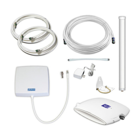
Fig. 1 Contents of kit.
PSU
Base unit
Fixings
Emitters
with s/a pads Eye
Coupler
Short flylead
Long flylead
Coaxial connectors
(one male, one female)

System components
This section gives a brief description of each part of the starLINK system.
Components supplied in this kit
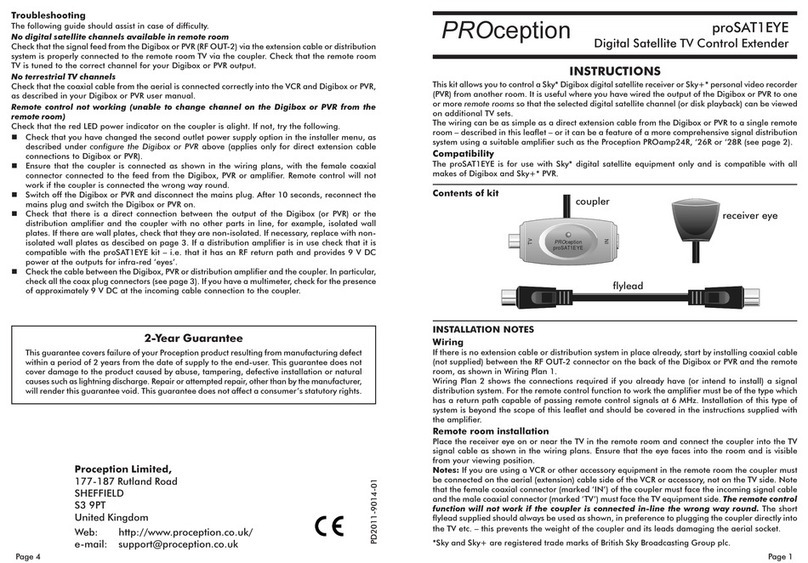
Eye located in the extension room the infra-red receiver eye picks up remote control
commands and sends them back along the TV signal cable to the base unit. The eye
consists of two parts: the receiver eye itself and the coupler which serves to connect the
eye into the signal cable.
Base unit this is located near to the source equipment and serves three purposes.
Firstly it splits the signal to feed both the local (main) TV and the extension rooms secondly
in a single-extension system it provides power to the remote eye and thirdly it interfaces
the commands from the extension rooms to the emitters or blaster.
Power supply unit (PSU) a plug-in power unit (mains adapter) which provides DC
power for the base unit.
Emitters the stick-on emitters supplied in pairs are small devices which attach to the
front of the source equipment you wish to control from the extension rooms. They plug
into the base unit and re-emit the infra-red commands relayed from the extension room(s).
Two emitter pairs can be connected to one base unit.
Sundries fixings coaxial plugs and flyleads.
Other accessories available
Additional eyes in systems using the PROception starBOX RF hub up to five or ten
extension rooms (depending on the starBOX model fitted) can be equipped with remote
control eyes. Additional eye kits are available separately (product code proSTL1EYE).
-R blaster the blaster accessory (product code proSTL1BLAST) is an alternative to the
stick-on emitters useful where more than two items of source equipment need to be
controlled or where the emitters are considered inconvenient. The blaster operates by
emitting higher-level infra-red radiation in a similar fashion to a remote control handset
and can be placed in the general vicinity of the source equipment.
Installation wiring
Typical installation wiring diagrams are shown in Figs. 2 to 5. These should be used as a
general guide to principles since the particular equipment installed will vary.
Fig. 2 Stan -alone application with a single extension room.
Page 7
Page 2
tsilkcehCstnemmoC
thgirehtgnisuuoyerA
ehtroftesdnahetomer
otgniyrterauoytnempiuqe
?lortnoc
!tsrifsgnihtsuoi
vbokcehC
gnivil(noitacolretsamehtsI
?KOnoitallatsni)moor
yltcerrocera)retsalbro(srettimednatinuesabehtta
htkcehC
llierehsmelborP.smargaidgnirieesdetcennocdnadellatsni
.smoornoisnetxeLLAninoitarepotceffa
det
cennocrelpuochcaesI
?dnuoryathgireht
tub,KOeblliserutcipVTsdrakcabdetcennocsirelpuocafI
.krotonllil
ortnocetomer
rotacidniDELderehtseoD
anehhsalfrelpuocehtno
?desserpsinottubtesdnah
esabehtmorfreopfokcal
asimelborpnommoctsomeht,tonfI
hcus,melborpnoitcennocaoteudyllaususisihT.XOBratsrotinu
nafoecneserpehtro
daelylfdegamad,gulpxaocdettifyldabasa
.ylluferacsnoitcennocllakcehC.)evobatxetees(etalpteltuodetalosi
relpuocehtotnoitcennocNIehtnoCDV9-8ebdluohserehT(
).yrassecenfiretemitlumahtikcehc
yaadenoitisopeyeeh
tsI
?secruosthgilthgirbmorf
VTehtro(spmaltnecseroulfmorfthgilthgirbrothgilnustceriD
sihT.noitarepotibihn
inaceyereviecerehtnognillaf)flestineercs
-erybtnemirepxE.gnihsalfrotacidniDELsrelpuocehtpotsoslalli
.
)spmalro(eyeehtgninoitisop
hsalfDELtinuesabehtseoD
noisnetxenanehder
?detarepositesdnahmoor
ehtdna)TUO(t
inuesabehtneetebnoitcennocehtkcehc,tonfI
metsysenola-dnatsanI.ytiunitnocCDrof)NRUTERFHU(XOBrats
.relpu
ocehtdnatinuesabehtneetebytiunitnockcehc
dnanoitcennocretsalbrorettimeehtkcehc,hsalfseodDELsihtfI
.gni
noitisop
ANT IN
PSU
ANT IN
RF OUT
emitters
OUT
TV
IN
Base unit
Main TV
UHF
aerial
proSTL1EYE (starLINK)
Coupler
Long flylead
(supplied)
RF OUT
VCR
Freeview
Coax plug (m)
Coax plug (f)
Short flylead
(supplied)
Troubleshooting hints
The following list may help if you are experiencing remote control problems.
OVERHEATING
The recommended ventilation clearances and other precautions given in the relevant section
of this instruction leaflet should e o served to prevent overheating. No unit should e fixed
where it is likely to ecome smothered y soft furnishing fa rics such as curtains, or y thermal
insulation material in a roof space or uilding void. Mains powered equipment should not e
left resting on a carpet.
WATER AND FIRE RISKS
Components of this kit are not waterproof. They are intended for indoor use only and must not
e placed where they could e exposed to dripping or splashing water. O jects containing
liquids should not e placed on or near the components.
To prevent risk of fire, no o ject with a naked flame should e placed on or near any of the
components or the associated wiring.
MAINS POWER SUPPLY UNITS
The power unit supplied as part of this kit is suita le only for use with 13 A sockets to BS 1363.
Consult a qualified electrician if the socket outlets in the location where the appliance is to e
installed are of a different type.
FIXED WIRING
Any fixed wiring installed to supply power to this system should comply with BS 7671 (IEE
wiring regulations, 16th Edition) and, where relevant, Part P of the uilding regulations. The
power unit is of Class 2 construction and does not require a protective earth connection. This
does not o viate the need to provide a circuit protective (earth) conductor in the supply wiring,
as required y BS 7671.
* Sky and Sky+ are registered trade marks of British Sky Broadcasting Group PLC.
Freeview is a registered trade mark of the British Broadcasting Corporation.
Safety Instructions

Page 3Page 6
Fig. 3 Master location wiring for starBOX system with Sky+*
Fig. 4 Master location wiring for starBOX system
with a Freeview receiver.
Tuning
In a new installation extension room TVs will need tuning-in to the output channel(s)
from the source equipment at the master location (usually the main living room). To
tune-in these TVs leave a tape or disk playing on a VCR or DVD player or select a known
channel on a digital receiver then tune an unused channel setting on each of the remote
TVs into the video or digital programme. Repeat this procedure for each set-top item. For
instructions on how to tune a TV refer to its instruction manual or the manufacturers
help line or Web site. In starBOX systems similar tuning will be required for the CCTV
camera output where installed.
If more than one item of set-top equipment is connected in the system you may experience
severe interference (patterning) when more than one output channel is present. In this
case the output channel number (modulator channel) for one or more items will need to
be changed and the relevant TVs retuned.
Testing
Once installation is complete and TV pictures are available in all extension rooms test
the system to ensure that remote control of each item of source equipment is working in
every extension room. For example if you are watching a Freeview or Sky* Digital channel
from a Freeview or Sky* box in the living room it should be possible to control the
relevant box from any extension room equipped with a starLINK eye. The normal remote
handset for each item of equipment should be used (or alternatively a suitable universal
handset programmed for your equipment).
During testing you may need to experiment with the positioning of the eyes and/or emitters
to obtain reliable operation of the system. The LED indicators provided on the eye couplers
and base unit can help with testing:
nThe coupler LED should flash red whenever a remote control command is received by
the eye.
nThe base unit LED is a 2-colour device: green for power-on indication and red to
indicate when remote control commands are being received from an extension room.
Telephone line
Master outlet plate
ANT IN
Hi-Fi
tuner
Main TV
ANT IN
Freeview
RF OUT
MASTER OUT
LNB2 OUT
UHF RETURN
From starBOX
VCR
PSU
emitters
OUT
TV
Base unit
Long flylead
(supplied)
IN
ANT IN
RF OUT
Telephone line
Master outlet plate
ANT IN
Hi-Fi
tuner
Main TV
ANT IN
VCR
RF OUT-1
MASTER OUT
LNB2 OUT
UHF RETURN
From starBOX
Sky+
PSU
emitters
OUT
TV
Base unit
Long flylead
(supplied)
IN
ANT IN
RF OUT
LNB1
LNB2
Avoiding problems
Some dos and donts
nEach eye should be positioned to face toward the viewing area of the room. Avoid
placing an eye where it could be exposed to full sunlight or near other bright lights
particularly compact fluorescent lamps. (These light sources could inhibit correct
operation of the infra-red receiver.)
nDont plug the coupler directly into the aerial socket of a TV since its weight could
place excessive stress on the TVs connector and cause damage. Always use the short
flylead supplied for this purpose.
nDont cut off an unused emitter (see Page 5).
nThe signal connections to the extension rooms
must not include any isolated outlet plates.
These will not pass the power supply from
the base unit or starBOX to the eyes and will
need to be replaced to ensure correct
operation of the system.
Fig 7. Ol isolate outlet plates are
not compatible with the starLINK system.

Hi-Fi
tuner
proSTL1EYE
Coupler
From
starBOX
Short flylead
(supplied)
LED
Page 5Page 4
Single extension room (stand-alone application)
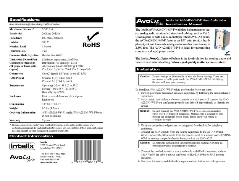
The installation wiring diagram for the basic single-extension system is shown in Fig. 2.
The wiring steps for this application are as follows:
1. Divert the aerial lead from the main TV to the IN connector of the base unit.
2. Connect the longer flylead supplied between the TV connector of the base unit and
the TV aerial socket.
3. Run a coaxial cable connection from the OUT connection of the base unit to IN
connector of the coupler in the extension room. The coaxial connectors supplied in
the kit will need to be fitted to the ends of the cable (see coaxial connectors on Page
5). Note that the female connector is used at the base unit end (master location) and
the male connector at the extension room end.
4. Connect the TV end of the coupler to the TV via the shorter flylead supplied.
5. Position the receiver eye on top of the TV or in a suitable nearby location facing
toward the seating or TV viewing area of the room.
Now connect the power unit and emitters (or blaster) to the base unit and you should
have a working system see the notes on tuning and testing below.
Multiple extension rooms (star OX systems)
Typical master location wiring is shown in Fig. 3 for Sky* or Sky+* systems and Fig. 4 for
a Freeview system. (These diagrams assume that the starBOX system has been installed
in accordance with the instructions supplied.) Note that a new flylead (not supplied) will
be required to connect between the base unit (OUT) and the RETURN input socket on the
master outlet plate.
In all cases the input to the base unit should come from the final item of source equipment
in the signal chain and the return feed to the starBOX must be taken directly from the
OUT connector of the base unit.
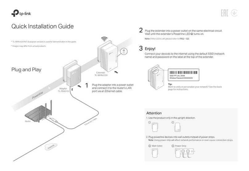
Extension room wiring is shown in Fig. 5. Take care to ensure that the coupler is connected
the right way round (the IN and TV connectors are clearly marked). Where a dual TV &
radio outlet plate is installed in the extension room as shown in the figure take care to
connect the coupler and TV to the TV side of the plate. If further set-top TV equipment
such as a local VCR or Freeview box is to be used in an extension room it should be
connected between the coupler and the TV. The output channel from such equipment will
only be available in that extension room.
Fig. 5 Extension room wiring (showing optional VHF ra io tuner). Eye installation with an existing TV
Where an extension room already has a TV installed follow these steps to install the
starLINK eye:
1. Unplug the aerial lead from the TV and plug it into the female IN connector of the
coupler.
2. Plug the male TV connector of the coupler into the TVs aerial socket via the short
flylead provided.
3. Position the receiver eye on top of the TV or in a suitable nearby location facing
toward the seating or TV viewing area of the room.
4. Select a VCR or set-top box channel on the TV and check that remote control operation
of the relevant source equipment is working.
General installation notes
ase unit and power supply
The base unit should be fixed to a wall skirting board or similar surface using the fixings
provided. Connect the output of the power supply to the base unit before connecting the
the power unit to the mains supply.
The power unit supplied is for use with a standard UK (BS 1363) mains socket-outlet only.
Before connecting this equipment to the mains supply read the safety instructions on
page 7. Disconnect the power unit from the mains whenever the equipment is to remain
unused for long periods of time.
Emitters or blaster
One emitter device should be stuck to the front of each item of source equipment. The
exact positioning is not usually very critical but it is recommended to experiment with the
position of each emitter (see the section below on testing) before sticking it in place. The
emitter housings are transparent to infra-red and do not interfere with normal local
operation of the equipment. The low-tack sticky pads supplied in the kit allow the emitters
to be removed easily when necessary.
The emitters plug into the jack connectors on the top of the base unit. Up to two emitter
pairs may be connected. If one of the emitters of a pair is unused it should be tucked
away behind the equipment. Do not cut an unused emitter off the wiring harness as this
will stop the other one working (they are wired in series).
Separate instructions are supplied with the blaster accessory.
TV
Coaxial connectors
The connectors supplied may be used for the ends of the extension cable run in the
stand-alone (single extension room) application or for making-up a flylead. The correct
method of fitting the connectors is illustrated in Fig. 6. For best results the use of a
double-screened (tape and braid) cable such as CT100-type or WF100 is recommended.
Fig. 6 Fitting the coaxial connectors
tighten terminal screw
for centre conductor
Braid wires folded ack over ca le
clamp (do not allow stray wires to
touch inner conductor) Remove ca le
foil where necessary.
inner conductor
4 mm
10 mm
Other PROception Extender manuals
