Einführung Deutsch
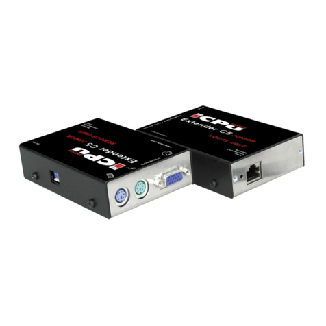
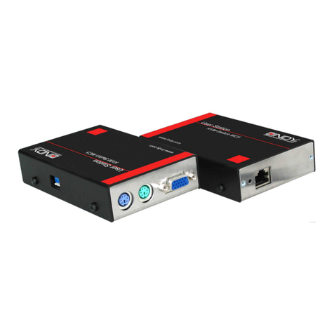
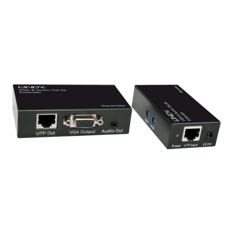
Der LINDY Cat.5 VGA Extender Smart überträgt hochauflösende VGA
Signale bis 1920x1200 oder 1080p über Distanzen bis 150m über
Twisted Pair Netzwerkkabel der Cat.5e/6.
Der Extender benötigt kein eigenes Netzteil, der Transmitter wird über
seinen USB Port mit Strom versorgt, und der Receiver erhält seinen
Strom über das RJ45 Kabel vom Transmitter.
Für den Fall, dass an der VGA Signalquelle kein freier USB Port zur
Verfügung steht, kann die Stromversorgung durch ein optionales USB
Netzteil, z.B. LINDY Art.-Nr. 73093 erfolgen.
Eigenschaften Deutsch
•Unterstützt hochauflösende VGA Signale bis 1920x1200 oder 1080p
über Distanzen bis 150m
•Das EDID/DDC Signal wird nicht über das RJ45 Kabel übertragen.
Der Transmitter emuliert das EDID/DDC Signal kontinuierlich, auch
bei unterbrochener RJ45 Verbindung. Bei Bedarf können die
EDID/DDC Daten des Monitors in den Transmitter kopiert und
permanent gespeichert werden
•Unterstützt Standby und Stromsparmodi
•Verbindung über kostengünstiges RJ45 Verbindungskabel – bitte in
der benötigten Länge separat bestellen
Lieferumfang Deutsch
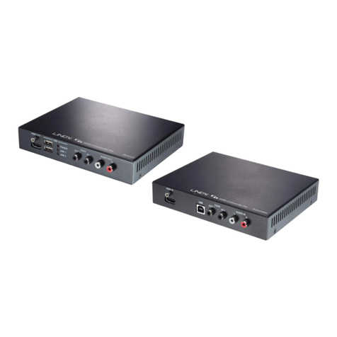
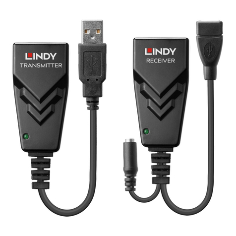
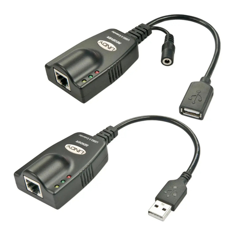
1x Transmitter mit VGA- und USB Anschlusskabel
1x Receiver mit VGA- und USB Anschlusskabel
1x Diese Anleitung
Installation und Betrieb Deutsch
!!! WICHTIGER HINWEIS !!!
Dieser Extender darf nicht an Ihr Netzwerk angeschlossen werden!
Schließen Sie NIEMALS andere elektronische Geräte an den RJ45
Anschlüssen an!
Cat.5/6 Verbindungskabel
Verwenden Sie abgeschirmtes STP/FTP Kabel um Transmitter und
Receiver zu verbinden. Für Längen bis 50m kann in der Regel normales
Patchkabel verwendet werden. Für große Längen liefert abgeschirmtes
Netzwerkkabel STP/FTP mit starren Adern (Installationskabel) mit
angecrimpten RJ45 Steckern die besten Resultate für die Bildqualität.
Falls verfügbar verwenden Sie bitte Low Skew Kabelmaterial. Kabel mit
zu großem Skew (Längenunterschied der einzelnen verdrillten
Adernpaare) bewirken, dass die RGB Signale zu unterschiedlicher Zeit
am Monitor ankommen. Daraus ergibt sich, dass weiße Punkte oder
vertikale Linien rechts und links einen Farbsaum bekommen.
•Schließen Sie den Transmitter an Ihre VGA Signalquelle an. Schließen
Sie das USB Kabel an einen freien Port Ihrer Signalquelle (Computer)
an; der USB Port muss 0,5A liefern können, Ports von USB Hubs ohne
eigenes Netzteil sind dafür nicht geeignet. Falls kein USB Port zur
Verfügung steht verwenden Sie bitte ein optionales USB Netzteil, z.B.
LINDY Art.-Nr. 73093
•Schließen Sie das eine Ende des RJ45 Kabels an. Verwenden Sie
möglichst ein direktes Verbindungskabel ohne zusätzliche
Steckverbindungen. Schließen Sie keine elektronischen
Netzwerkgeräte an!
•Schließen das andere Ende des RJ45 Kabel an den Receiver und
diesen an Ihren VGA Monitor an und schalten Sie alles ein.
EDID / DDC Emulation
•EDID/DDC Daten werden nicht über das RJ45 Kabel übertragen. Der
Transmitter verwendet einen gespeicherten Satz von EDID/DDC
Auflösungen bis 1920x1200 und 1080p. Falls damit die Auflösung Ihres
Monitors nicht korrekt an der Signalquelle (Grafikkarte) eingestellt
werden kann, oder wenn bestimmte vorgespeicherte Modi nicht
einstellbar sein sollen, so kann der Transmitter die EDID/DDC Daten
Ihres Monitors auslesen und permanent speichern. Dazu gehen Sie
folgendermaßen vor: Versorgen Sie den Transmitter mit Strom über
seinen USB Port, schließen Sie ihn an den Monitor an und schalten Sie
den Monitor ein. Die gelbe LED am Transmitter wird für 2 – 3
Sekunden blinken während die EDID / DDC Daten im Transmitter
permanent überschrieben werden. Ziehen Sie den Transmitter ab und
installieren Sie ihn wie geplant. Bei einem Problem zeigt die gelbe LED
eine bestimmte Anzahl von Blinksignalen. Wiederholen Sie den
Vorgang, notieren Sie die Anzahl und kontaktieren Sie den LINDY
Support.
Einstellung der Bildschärfe
•Verwenden Sie eine mit Word oder einem Texteditor erstellte Textdatei
mit großen schwarzen Buchstaben auf weißem Hintergrund.
•Stellen Sie die Schraube am Receiver so ein, dass die senkrechten
Linien möglichst scharf und das Bild möglich gut werden.
•Sollten an senkrechten Kanten Farbsäume auftreten so ist der Skew
ihres RJ45 Kabels zu hoch. Verwenden Sie ein Kabel mit geringerem
Skew oder einen VGA Extender mit Skew-Kompensation.
LED Anzeigen
Der Receiver wird über das RJ45 Kabel vom Transmitter mit Strom
versorgt. Der Transmitter wird über den USB Stecker mit Strom versorgt.
Der Transmitter prüft die Verbindung (gelbe LED blinkt) bevor er die
Versorgungsspannung auf das RJ45 Kabel anlegt (gelbe LED leuchtet
kontinuierlich). Der Transmitter unterbricht die Stromzufuhr wenn:
•Das RJ45 Kabel abgezogen oder unterbrochen wird
•Bei Kurzschluss zu viel Strom gezogen wird
Standby und Stromsparmodi
Wenn der Host Computer oder die VGA-Signalquelle in Standby gehen
(Abschalten des Monitorsignals, normalerweise Abschaltung der Sync
Signale) schaltet der Transmitter mit einer Verzögerung von ca. 16
Sekunden auch die Stromzufuhr zum Receiver ab und fällt in seinen
eigenen Stromsparzustand. Die gelbe LED erlischt bis der Transmitter
wieder ein Bildsignal erhält.
Hilfe bei Problemen Deutsch
Bei Problemen mit der Bildqualität prüfen Sie bitte alle oben genannten
Punkte. Wenn Sie die Probleme nicht lösen können, notieren Sie die
Anzeigen der gelben LEDs und kontaktieren Sie den LINDY Support.
FCC Compliance Statement
This equipment generates, uses and can radiate radio frequency energy and if not
installed and used properly, that is, in strict accordance with the manufacturer’s
instructions, may cause interference to radio communications. It has been tested and
found to comply with the limits for a Class A computing device in accordance with the
specifications in Subpart J of part 15 of FCC rules, which are designed to provide
reasonable protection against such interference when the equipment is operated in a
commercial environment. Operation of this equipment in a residential area may cause
interference, in which case the user at his own expense will be required to take whatever
measures may be necessary to correct the interference. Changes or modifications not
expressly approved by the manufacturer could void the user’s authority to operate the
equipment. The extender should be operated with shielded cables only.
Recycling Information
WEEE (Waste of Electrical and Electronic Equipment),
Recycling of Electronic Products
In 2006 the European Union introduced regulations (WEEE) for the collection and
recycling of all waste electrical and electronic equipment. It is no longer allowable to
simply throw away electrical and electronic equipment. Instead, these products must enter
the recycling process.
Each individual EU member state has implemented the WEEE regulations into national
law in slightly different ways. Please follow your national law when you want to dispose of
any electrical or electronic products.
More details can be obtained from your national WEEE recycling agency.
Germany
Die Europäische Union hat mit der WEEE Direktive Regelungen für die Verschrottung und
das Recycling von Elektro- und Elektronikprodukten geschaffen. Diese wurden im
ElektroG in deutsches Recht umgesetzt. Dieses Gesetz verbietet das Entsorgen von
Elektro- und Elektronikgeräten über die Hausmülltonne! Diese Geräte müssen den
lokalen Sammelsystemen bzw. örtlichen Sammelstellen zugeführt werden! Dort werden
sie kostenlos entgegen genommen. Die Kosten für den weiteren Recyclingprozess
übernimmt die Gesamtheit der Gerätehersteller.
LINDY No.32666
www.lindy.com
First Edition FEB 2011
Tested to Comply with FCC Standards
For Commercial Use Only!


